PISTON PIN HONING MACHINE
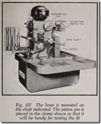
Fig. 107 illustrates a machine for honing piston pin holes and connecting rod bushing holes. It is more accurately called a grinder. It can be used for other small holes-kingpins, for example.
The piston is placed on the hone and the micrometer dial is turned until the mandrel is ex panded to fit the hole. The hone should be co piously lubricated throughout the honing process. This is accomplished by a built-in oil pump which delivers a steady stream of oil.
Start the machine and stroke the piston back and forth. Slowly turn the dial to the right until it begins to cut. Stroke the piston back and forth on the hone while holding it in both hands. When the piston feels “free”, retract the hone by pressing the floor pedal. Remove the piston, turn the dial to expand the hone a few thousandths. Put the pis ton back on the hone. Remove foot from pedal to allow the hone to expand. Stroke the piston back and forth at the rate of about 20 complete strokes per minute. Every few strokes remove the piston and reverse it. Whenever removing or replacing piston always depress pedal to retract hone.
When the piston feels free, remove it and try the piston pin for fit.
Expand the hone a little more and repeat the process and so on until the fit is perfect.
Note that as the pin hole approaches the de sired size, the micrometer dial should be ad vanced with caution. When the fit is almost per fect the dial should be advanced only a fraction of a ten thousandth of an inch. When the pin fits perfectly, place it inside the upturned piston.
After sizing the pin hole in the first piston, turn the micrometer dial back about 5 ten thousands ( .0005″) and hone the other piston holes to this diameter. Then hone the holes in each piston to the exact fit required for the pin selected for it.
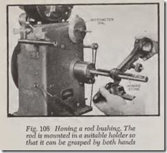
The procedure for honing connecting rods is the same as for pistons. The rod should be mounted in a holder, Fig. 108, so that it can be properly grasped in both hands.
The instructions given above are intended to give the reader a general idea as to how a honing machine is used. However, it is strongly recom mended that when using this or any other ma chine the manufacturer ‘s instructions should be carefully followed.
CHECK ROD ALIGNMENT
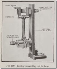
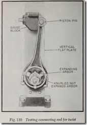
The alignment of both old and new rods should be checked before they are installed. There are a number of aligning tools in use including those illustrated in Figs. 109 and 110.
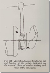
The rod should be checked for bend and twist. If the rod is bent its piston pin will not be parallel with the crankpin, Fig. 111. This cocks the rod bearing on the crankpin, causing extra wear where the bearing is pinched-as shown by the arrows. The same thing happens at the piston pin.
In a twisted rod, Fig. 112, the piston pin bore is not in fore-and-aft alignment with the crankshaft axis and may cause increased wear on rod bear ings, piston pin and piston.
When checking a rod, the bearing cap should be tight but do not install the rod bearings.
The rod aligning tool, Fig. 109, is permanently mounted on the bench. To the base is bolted a vertical flat plate and the aligning gauge block is mounted on it. The base of the gauge block fits around the left edge of the plate, Fig. 110. There is a clamp nut at the rear so that the block can be positioned for any length of rod.
To check a rod, install the piston pin and the bearing cap but not the bearings. Tighten the rod nuts to torque wrench specifications.
Expand the arbor by turning the nut until the arbor is firmly seated in the rod bore.
To check the rod for bend, place the gauge block in the position shown in Fig. 109 with the legs of the gauge resting on the pin. If only one leg makes contact, check the clearance with a feeler. If the clearance is more than .002″ the rod should be straightened with the bending iron shown in Fig. 113 until clearance is less than .002″ or until no light can be seen between pin and block.
To check the rod for twist, place the aligning gauge in the position shown in Fig. 110 and clamp it in place. Then bring the pin in contact with the gauge. If one end of the pin fails to contact the gauge, check the clearance with a feeler. If more than .002″, the rod should be untwisted until clearance is less than .002″. Then recheck for both bend and twist.
After the piston and rod are assembled, check the alignment of the piston. Its top surface should be parallel to the gauge within .002″. Use the set up shown in Fig. 109.
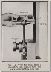
Fig. 114 shows another make of tool for testing connecting rod alignment. The rod is clamped in position vertically as shown. The gauge block has a V groove to center it on the piston pin. The gauge block is placed horizontally to determine twist and vertically for bend.
Two round nubs contact the vertical Bat plate if the rod is in alignment. If one of the nubs has a clearance of .002″ the rod should be straightened.
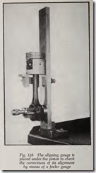
Another design of aligning tool is seen in Figs.115 and 116. The knurled nut expands the arbor until it fits the rod bore. A special straightening tool is used, Fig. 115. Turning the screw straight ens the rod. Fig. 116 illustrates how the tool is used for checking piston alignment.
ASSEMBLE PISTON TO ROD
Match up piston and rod according to their marks, so that they are in correct relationship.
Wipe off pin with clean cloth and wipe out bores in piston. Coat pin with engine oil.
Hold the piston in one hand. Start the pin into the piston and push it about J!J” beyond the inner edge of the boss. Then install the rod over the pin and push the pin through the secon d boss.
If the pin is a light tap fit, start the pin into the hole by hand. Then, while holding the piston in one hand, tap the pin lightly with a soft hammer. Or install a soft drift in the pin and pound the
drift lightly on the bench or tap the drift with a hammer.
If the pin is locked to the rod, be sure the flat or groove in the pin lines up with the lock screw in the rod.
If the pin is locked to th e piston, line up the hole in the pin with the lock screw. If one end of this pin is split insert this end first.
If the new pistons with pins already fitted hap pen to be tighter than a light tap fit, as they are in some engines, heat the pistons in boiling water or on an electric hot plate before installing pins. This recommendation applies to very tightly fitted pins with a clearance of .0001″ or less, down to .0003″ negative clearance-that is the pin is .0003″ larger than the pin holes in the piston .
PISTON AND CONNECTING ROD
ASSEMBLY FOR HIGH PERFOR MANCE
Pistons that are typically used in high perfor mance engines combine strength and durability and lightweight characteristics with controlled heat expansion features, along with dome and skirt configurations that permit proper working clearances at all temperatures that are likely to be experienced.
They are selected to provide the desired com pression ratio.
Chrome piston rings are highly desirable in high performance engines. One authority claims an ad ditional 19 horsepower through careful selection of piston rings.
Connecting rods, in addition to being Magna fluxed, checked for alignment and de-burred, must be balanced with great accuracy. Special high performance rods have weight milling pads at both ends for balancing purposes.
When installing rods to the crankshaft, torque the caps to specification, rotate the shaft, remove the bearing cap and inspect it for burrs on the bearing surface. This is an extra precaution before final assembly.
Review Questions
1. What is the function of the piston system? ………………………………… .
2. Name the parts of the piston system ………………………………………. .
3. Most repairs to the piston system are made for what purpose? ………………….. .
4. How do worn engine bearings affect oil consumption? ………………………… .
5. Which causes more wear, pistons or rings? ………………………………… .
6. Viewing the engine from the driver’s seat, which side of the engine is the major thrust side?
7. Under what operating condition does the most wear take place in an engine? ……… .
8. Why does the top piston ring wear faster than the other rings? ………………… .
9. Explain what condition would result in piston slap. . ………………………… .
10. Why is it necessary to break the glaze on cylinder walls in the process of doing a ring job?
11. What are the two common causes of pressure build-up in the crankcase? …………. .
12. What might be the result of excessive crankcase pressure? ……………………. .
13. What three ways can oil pass into the combustion chambers? ………………….. .
14. Blue smoke from the exhaust indicates what condition? ……………………… .
15. How does a leaky vacuum pump diaphragm cause high oil consumption? …………. .
16. How may an “invisible” crack in a cylinder block be detected? ………………….. .
17. What three methods may be used in repairing cracked blocks? ………………… .
18. After the cylinder head and oil pan have been removed, what important operation must be performed before the pistons are removed for the purpose of installing new rings? .. . .. .
19. What might be the result if new piston rings were installed without removing the ring ridges? ……. .. ……………………………….
20. Why is it so important to install the same pistons and rods in the cylinders from which they were removed? ……………………………………..
21. Why should connecting rods never be identified by file marks? ………………… .. .
22. In what portion of a worn cylinder bore should a piston ring be placed to measure the end gap? …………………………………………….
|
23. |
What could be the result of installing piston rings with insufficent end gap? ……….. . |
|
24. |
What type of piston ring does not require an end gap? ……………………….. . |
|
25. |
What tool should be used to install rings on pistons? …………………………. . |
|
26. |
What is the last thing to do before installing piston and rod assembly in the cylinder? |
|
27. |
What tool should be used when installing pistons in cylinders? ………………. .. . |
|
28. |
When cleaning aluminum pistons, what type of solution should be avoided? ……….. . |
|
29. |
What is the purpose of the narrow groove above the top ring on some pistons? ……… . |
|
30. |
Why is it necessary for piston rings to move freely in their grooves? …………….. . |
|
31. |
What three methods are used to expand piston skirts? ……………………….. . |
|
32. |
What three measurements should be taken of cylinder bores in order to determine if a rebore job is needed? …………………….. |
|
33. |
Describe three methods of measuring cylinder bores ………………………….. . |
|
34. |
What is the purpose of a glaze buster? ……………………………………. . |
|
35. |
When should a flexible hone be used? …………………………………….. . |
|
36. |
Under what circumstances would the use of a rigid hone be preferable to a flexible hone? |
|
37. |
Under what circumstances would cylinder sleeves be used in an engine that had no sleeves originally? ….. . ……….. . |
|
38. |
How many methods are currently being used to retain piston pins? ………………. . |
|
39. |
Why is a “full-floating” piston pin so called? ………………………………… . |
40. What iS an “osci·llatm· g” pi·ston pin ? ………………
41. If a press is not available, describe a simple method of removing a piston pin bushing from a connecting rod ………………………………
42. What precaution should be taken when installing a connecting rod bushing having an oil hole? ……………….
43. What is the purpose of “swaging” a connecting rod bushing? …………………….
44. What is the purpose of checking connecting rod alignment? …………………….
45. In what two ways might a connecting rod be out of alignment? …………………
