Cylinder Bore Service
CHECK CYLINDER BORES
Befor e cleaning or inspecting the worn pistons it is advisable to measure the cylinder bores. If bore taper is more than .015″, the cylinders should be rebored and new pistons and rings installed. Hence it is a wast e of t ime to inspect the worn pistons if new pistons must be installed.
There are three sets of measurements to deter mine taper, out-of-round and wavy bore. Usually it is sufficient to m easure the bore for taper and forget th e other two. If taper is more than .015″, the cylinders should be rebored. If less than .015″ install new rings.
CYLINDER BORE TAPER
This measur em ent is taken crosswise of the engine because greatest wear can be expected to be crosswise. The bore is measured: ( 1) At the top of th e ring travel just below the point where the rid ge was rem oved . ( 2 ) At the bottom of the bore. Subtract mea surement 2 from 1 to get the taper. Example: Diameter at top, 3.019″; at bot tom, 3.002″; taper is .017″.
OUT-OF-ROUND BORES
Worn bores are no longer circular but oval. The diameter crosswise of the engine is larger than the diameter fore and aft. This measurement should be taken at top and bottom of bore-and at inter mediate points if deemed necessary. The differ ence between the crosswise diameter and fore-and aft diameter at the upper end of the ring travel indicates the amount the bore is out-of-round at this point. Similarly for bottom of bore and inter mediate points.
If the cylinders are out-of-round more than .005″ reboring is recommended. However, one of the more conservative ring manufacturers states that rings installed in cylinders that were out-of round .010″ have satisfactorily controlled oil con sumption, adding that cylinders are more nearly round when warm. This company points out that if the rings are able to follow the taper, the out-of roundness of cold cylinders can usually be ig nored.
WAVY BORE
Measure bore at several points from top to bottom crosswise of engine to detern1ine whether the surface has waves or high and low spots. Also measure bore waviness lengthwise of engine.
Look for the possibility of a ridge at the lower end of the bore or the lower end of the ring travel. The ridge can be honed out.
If the cylinder has waves, holes or pockets more than .001″ deep, hone them out completely or at least until the depth is .001″ or less. If too deep
for economical h oning, rebore.
Look for scratches or gouges-score marks-in the bore. They can be hon ed out if not too deep. Otherwise, reboring m ay be required. It is not necessary to rebore the oth er cylinders unless they need it.
CYLINDER BORE MEASURING INSTRUMENTS
Cylinder bores can be measured by ( 1) a dial gauge, ( 2) an inside micrometer, ( 3) a telescope gauge and outside micrometer. Note that microm eters may go out of adjustm ent, therefore, always check the zero point before taking a measurement, and adjust if necessary. Cylinder bore taper can also be measured with a set of long feeler gauges.
Dial Gauge Method
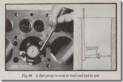
Adjust the thrust pin of the dial gauge, Fig. 68, so that it must be pushed in about W’ when it is inserted in the bore. The best way to use the dial gauge is to adjust an outside micrometer to the exact size of the original bore. Then fit the dial gauge between the contacts of the micrometer and adjust the dial carefully to rea d zero. Or dispense with the outside microme ter and set the dial gauge to read zero when close to the bottom of the bore where wear is slight.
Check for Taper, Out-of-R ound and Wavy bore as already explained. For example, the reading of the dial gauge at the top of the bore crosswise,
minus the reading at the bottom of the bore, gives the amount of taper in thousandths of an inch.
Inside Micrometer Method
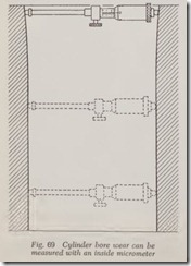
With the inside micrometer, Fig. 69, measure the bore at the various points mentioned above and note the readings.
Telescope Gauge and Outside
Micrometer Method
The telescope gauge, Fig. 70, consists of a rod slidably mounted in a tube. Insert the gauge in the bore and adjust it until it just fits the bore at the place selected. Then remove the gauge and measure the diameter with an outside micrometer.
Feeler Gauge Method
The taper can also be measured with a set of long feeler gauges or by various thicknesses’ of shim stock This method is not as accurate as the micrometer or dial gauge methods. Be sure the surfaces involved are free of oil.
One of the old pistons may be used for this job.
Feelers of various thickness are used to measure the approximate clearance at top and bottom of bore. The difference in feeler thicknesses gives the taper.
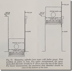
The feeler clearance is measured crosswise of the engine because this is the direction of greatest wear. Fig. 71 shows how the feeler is used. The piston should be upside down with the piston pin fore and aft of the engine. Insert the feeler and the piston together, with the lower end of the feeler extending down beyond the piston skirt. The piston skirt is largest near the top of the skirt. Therefore this part of the skirt should be opposite the top and bottom of the bore when the feeler measurements are taken. At top and bottom, try feelers of various thicknesses until one is found that can be moved with a very gentle pull-while the piston is held stationary in the bore. Consider this the clearance at top or bottom as the case may be. The difference in feeler thickness required at top and bottom indicates the-amount of taper.
Feeler gauges come in various thicknesses from .001″ up by thousandths or half thousandths. In checking piston clearances usually a W’ wide gauge is used but occasionally the one inch wide gauge is specified. The length should be about 12 inches for most cylinder bores. For accurate work the gauge should not be kinked, bent or ragged.
Cylinder Bore Service Equipment
GLAZE BUSTER OR BREAKER
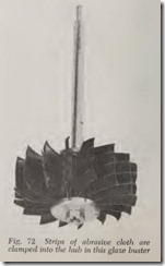
A glaze buster is designed solely to remove the glaze on the cylinder bore. The glaze buster shown in Fig. 72 consists of numerous pieces of special abrasive cloth which are clamped in slots in the hub. The pieces may be reversed or re placed by loosening the nut.
The buster is operated by an electric drill. Dip the abrasive in kerosene. Install the drill and move up and down in bore for 30 seconds. Then give it another coating of kerosene and operate it for an other 30 seconds. Wipe bore clean.
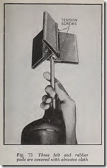
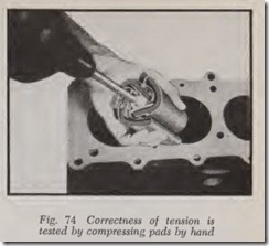
The glaze breaker, Figs. 73 and 74, has three “pads” (made of laminations of felt and rubber) covered with abrasive sheets furnished in both medium and fine grit sizes. The three “tension” plates at the base of the pads can be adjusted to give the correct pad stiffness for all cylinders from 3″ to 4) ” or even larger. The plates are correctly adjusted when they are readily compressed by hand, Fig. 74, so that they can be inserted in the cylinder. For cylinders smaller than 3 inches (down to 2.6″ bore) the tension plates are removed.
The glaze breaker is mounted in an electric drill and 8 or 10 complete strokes (up and down) are usually sufficient to remove the glaze. To reduce flying abrasive to a minimum the pads should be well s.Oaked in oil.
FLEXIBLE HONE
A flexible hone can be used for removing a small amount of metal from the bore-up to .003″.
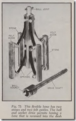
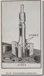
A typical flexible hone is shown in Figs. 75 and 76. It has two stones and two guides made of a felt composition. The hone is rotated by an elec tric drill. The stones and guides are pressed against the bore by both spring tension and cen trifugal force. The hone shown is suitable for bore diameters from 2-9/16″ to 4-3/4″.
Insert hone in cylinder and start motor. Move hone up and down at the rate of about 30 times per minute. Allow hone to protrude slightly at top and bottom of strokes. Examine bore after 20 or 30 strokes and repeat if necessary-until required amount of metal has been removed.
Coarse and fine stones are available . Use coarse stone for fast cutting and fine stones for finishing. If only a slight amount of metal is to be removed, use fine stones.
Carefully observe the manufactur er’s instruc tions as to care and use of hon e. If felt guides are impregnated, the hone may be used dry. Dry honing gives faster cutting. Wet honing (with kerosene) gives smoother finish. Kerosene is con veniently squirted on stones by means of ordinary oil can.
Stones must be kept clean . If dirty or gummed, clean with wire brush and kerosene.
For glaze removal, use 150 grit stones with rapid up and down motion of hone-fast enough so that the scratches the hone makes on the bore surface are at an angle of about 45 degrees.
The honing stones are expanded by springs plus the action of centrifugal force acting on the ro tating tool.
When used for removing glaze about 10 com plete strokes (up and down) should be sufficient.
How ever, the main purpose of the flexible hone is to smooth the bore when it is necessary to re move only a small amount of metal-not more than .003″. If more, use a rigid hone or rebore the cylinders.
If the bore is slightly scored, the flexible hone may be used to remove the marks if they arc not more than .003″ deep. If deeper, use a rigid hone or rebore.
The flexible hone has the advantage that it re quires no adjustment. Its disadvan tage is that it removes the metal very slowly. Therefore, if some what more than .003″ is to be rem oved it will save time to use a rigid hone. Another objection is that it follows the taper of the bore.
If the bore has high or low spots (waves or pockets) with a variation of .001″ or less they can be ignored but if the high and low spots are from .001″ to .003″, use a flexible hone to remove the high spots. It is not absolutely n ecessary to re move the low spots completely. A f ew low spots will do no harm, especially if they are less tl1an .001″ deep.
The flexible hone may be used to remove a ridge in the lower bore if not more than .002″ or .003″ deep. If the ridge is less than .001″ it can be
ignored. If more than .003″ use a rigid hone.
RIGID HONE
The stones in a rigid expanding hone are held firmly in place to whatever diameter they are adjusted. They are adjusted to the desired size by turning the micrometer dial which reads in thou sandths of an inch.
This hone may be used instead of a flexible hone for all work done by the flexible hone except glaze busting for which the rigid hone is not suited because it does not follow the taper of the bore.
Use a rigid hone to remove a ridge at the bottom of the bore if more than .003″. If less, use a flexible hone.
When bores are reconditioned by a rigid hone, they should be as good as new. That is, taper and out-of-round should be as little as .0007″ or even .0005″.
The rigid hone can be used for refinishing cyl inders which arc tapered up to .020″ but reboring may be faster and therefore more economical if much metal is to be removed. Opinions differ as to where the dividing line lies, that is, when does reboring become more economical than honing.
For the sake of argument, let us say that .007” taper is usually the economical limit. If taper is .007″ or less, honing may be cheaper but if more than .007” it may be more economical to rebore. But no two experienced men arc likely to agree as to whether the .007” figure is just right, or too high or perhaps much too low. The hardness of the cylinder block, the power of the electric motor and the skill of the operator all have a bearing on what the figure should be.
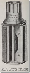
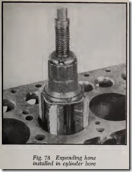
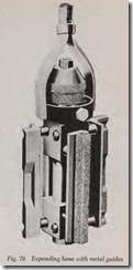
This hone usually has two stones and two guide blocks, Figs. 77, 78 and 79, although four stones and no guide blocks are sometimes recommended with wet honing (wet honing means the stones are wetted with kerosene). The guide blocks may be made of fabric composition as in Figs. 77 and 78 or may be of metal as in Fig. 79.
The stones are positively expanded by turning the micrometer dial. For quick expansion to the bore size, pull the micrometer nut upward and turn it counterclockwise until it fits the bore snugly (when hone is flush with top of bore). Then push the nut downward to bring the mi crometer into use. If the adjustment is too tight in the bore pull micrometer upward and back off slightly.
Carefully follow the manufacturer’s instructions both as to operation and care of the make and model of hone used. Be sure stones are clean. If not scrub them with a stiff brush and kerosene.
Note that most rigid hones have a micrometer nut with a scale reading from .000″ to .030″, Figs. 77 and 78. The scale is so large that tenths (of thousandths) are readily estimated.
The guide blocks should have from .010″ to .030″ clearance in the bore. If too tight, file, or dress with a rough honing stone. Tight guide blocks cause stones to chatter.
Stones must be clean or speed of cutting will be reduced. If coated with grease, oil or carbon, scrub with a stiff wire brush and kerosene. If they cannot be cleaned they should be discarded.
Tapered stones and guide blocks are caused by too little tension on the stones. This is avoided by frequent adjustment of the micrometer to keep the stones tight against the bore.
Before starting to hone, be sure the bores have been cleaned of oil and grease.
Crankshaft and camshaft should be completely covered with oily rags or wet newspaper so that no grit can reach any of the bearing wearing surfaces. This precaution is necessary not only for dry honing but also for wet.
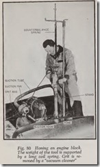
If the bores are to be dry honed, a grit remover is recommended, Fig. 80. It works like a vacuum cleaner. Its suction hood fits over the top of the hone and sucks away loose grit from the stones, delivering it to the grit bag.
If the bores are to be wet honed, the hone should be dipped into a pail of kerosene occasionally.
The hone manufacturer’s instructions should be carefully followed as to what stones to use, etc. However, on the average, coarse stones (about 150 grit) should be used for roughing and finer (about 250 grit) stones for finishing. If .003″ or less is to be removed, the job may be done with the finishing stones.
But if more than .003″ must be taken off, use the coarse stones to remove all but about the last .001″. Then switch to the finishing stones.
Place the hone well down in the bore and turn the micrometer nut until the hone just fits the bore. Turn the motor on and move the hone up and down in the lower bore with a steady motion,
at the rate of about 30 complete strokes per minute.
The lower end of the bore should be honed first, because it is smallest here. On the down stroke the hone should extend out of the bore about an inch. Initial up-strokes should be only about 2″.
Immediately after starting the hone, if the tension on the stones is not enough, stop the hone and expand the stones slightly by turning the micrometer but be sure not to increase the tension enough to slow the motor down. As honing pro ceeds, the gradually increasing bore size requires frequent adjustment of the tension by turning the micrometer. At the same time the length of the upstrokes is gradually increased, until finally full strokes are used with the stones protruding about an inch at both top and bottom.
Let us assume, for example, that .010″ oversize pistons are to be fitted and that the specified piston clearance is .002″.
Honing is begun with coarse stones and finished with fine stones. Continue honing one bore with coarse stones until it is within one or two thou sandths of finished size as determined by a micrometer or by trying a new piston in the bore. When the piston is a tight fit in the bore it is close to size.
Note the micrometer reading, and then rough hone all the other bores to this size.
Then change to the fine stones and fit each bore to the piston selected for it. Check the final piston fit with a .002″ feeler (since we assumed the specified piston clearance was .002″). The fit is correct when a 5 to 7 pound pull is obtained on the feeler, Fig. 81. Some shops dispense with the spring scale and simply “feel” the clearance by pulling on the feeler.
As soon as the fit is correct, the lower inner edge of the skirt should bP marked with scratch lines, the number of lines corresponding to the cylinder number-three lines for No. 3 cylinder, for ex ample.
When honing is finished, be careful to wash away all grit. Use plenty of soap and water and a stiff bristle brush.
REBORING
The cylinders should be rebored to :fit the near est oversize piston. Therefore if taper is .017″, for example, it is rebored for .020″ oversize pistons.
Pistons are usually available in the following oversizes: .010”, .020″, .030″, .040″, .050″-and perhaps .060”. There may also be oversizes less than .010″ such as .003″ and .005″.
The cylinder walls on some makes of engines are thicker than on others. Therefore some makes can be rebored to a slightly larger diameter than others.
If desired, the jobber shop can grind seminn ished pistons to any non-standard oversize, such as .017″ or .025″, etc.
The cylinders are rebored to within about .001″ of the desired size and then :finished to size by honing.
When the engine is rebored in the car, it some times happens that the rear cylinder is so close to the dash that the boring tool cannot be installed. In this case, the rear cylinder may be honed to size while the others are rebored.
Use of Boring Bars
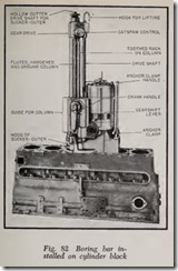
The following information is intended to give a general idea as to how a rebore job is done. Fig. 82 shows a boring bar mounted on a cylinder block.
Boring bars all use the same principle of a ro tating cutter driven by an electric motor to cut the metal from the bore. Naturally the details of the different makes of boring bars vary.
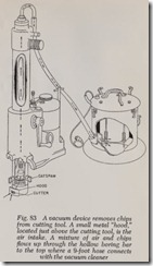
A Sucker-Outer, Fig. 83, is optional equipment on some models. It disposes of the chips. There is an electrically-driven fan which applies suction to a hood surrounding the cutter, picking up the chips that are carried up through the hollow cut ter shaft and delivering them to a container sur rounding the suction fan and its motor.
The torque required to rotate the tool depends on the bor e diamet er, the depth of cut and the hardness of the bore. A 50 per cent increase in bore diameter calls for a 50 per cent increase in torque; a deep cut requires more torque than a shallow cut; a hard bore demands more torque than a soft one. This explains why some of these tools have two to four speeds. The slower the speed the greater the torque.
One model has four speeds. The two higher speeds are for cast iron and the two lower speeds for hard steel sleeves. This model is described in some detail below.
Boring Bar Construction
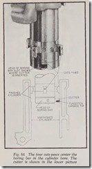
The complete tool installed on the block is shown in Fig. 82. A rotating cutter with a tungsten carbide tip, Fig. 84, rebores the cylinder. The cutter shaft rotates within the heavy column which is mounted in the body of the machine, Fig.82. The column does not rotate but it is fed downward by means of the toothed rack shown, which is operated by a gear in the base of the machin e. The cutter, of course, moves down with the column.
The cutter shaft is rotated by the drive shaft which is rotated by the transmission gears which are driven by the motor.
Preparation for Boring
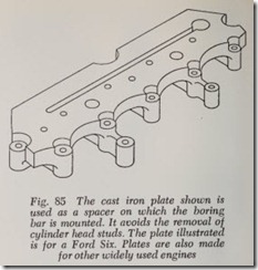
If the block has cylinder head studs instead of bolts the studs must be removed, or a boring plate should be installed, Fig. 85. The thickness of the plate is greater than the length of the studs.
Before beginning a rebore job, the top of the block must be clean and free of burrs so that the base of the machine can rest squarely on the block. If dirt tilts the bar the finished bore will also be tilted.
Before a cylinder can be rebored, the cutting head must be accurately centered in the bore and then the machine must be firmly clamped to the block.
Before placing the machine on the block, raise the column all the way to the top by turning the large crank handle slowly.
The cutter head is centered in the bore by the four cats-paws, Fig. 84. Retract the cats-paws by turning the outer knurled wheel on the cats-paw control located near the top of the columns, Fig. 82.
Then run the boring bar down into the bore until the cats-paws are near the bottom where wear is least. Expand the cats-paws until they are tight in the bore by turning the outer knurled wheel just mentioned.
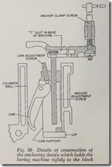
The anchor clamp, Fig. 86, holds the boring bar in place after it has been centered in the bore. The clamp is located in an adjacent bore. The device is inserted in the bore from underneath. The head of the long screw is slipped into the T-slot in the base of the boring bar and the screw is adjusted until the lip on the lower end of the clamp body is snug against the lower edge of the bore. Then turn down the cam adjustment screw until the cam is tight against the bor e-yet not tight enough to distort th e bore.
Turn down the anchor clamp screw until it is just snug against the top of the block. Do not tighten it enough to mar the block. This screw is seen to right of motor in Fig. 82.After the tool is centered, retract the cats-paws and turn the large crank slowly to raise the cutter head up to the top of the bore.
Cylinders are rebored to within about .001″ of finished size and then finished to size by honing. Each piston is individually fitted to its bore during the honing process and checked for fit with a feeler. The procedure is the same as described for finish honing.
The next step in reboring is to set the cutter to the desired oversize. For example, assume that the original cylinder bore was 3) ” or 3.125″ and that .020″ oversize pistons are to be fitted. Assume also that piston clearance for this make and model of engine is .002″. Therefore, the refinished bore diameter will be 3.125″ plus .020″ plus .002″ clearance or 3.147″. However, .001″ should be left
for honing. Consequ ently, the cutter should be s:t to 3.146″. All cylinders should be bored to th1s size.
Boring Procedure
Boring is started by engaging the clutch which operates the feed gearing. This is done by pulling out on the ring on the crank handle shaf t, Fig. 82. Immediately start expanding the cats-paws slowly and evenly until they touch the finished bore. Continue to exert pressure on the cats-paws until they have completely entered the bore. Continue to hold the outer knurled wheel while you en gage the pawl and ratchet on the inner knurled wheel until a definite resistance is felt. The paws are now set and need no further attention while the boring of the cylinder is in progress. The cats paws steady the cutter head and prevent chatter ing of the tool.
The cutter, with its tungsten carbide tip is shown in the lower half of Fig. 84. It fits into a slot in the cutter head . The slot is clearly illus trated in the upper pictur e.
To adjust the cutter, it is removed and placed in a special micrometer fixture which is supplied with the boring bar.
After the cutter is adjusted, it should be in serted in the cutter head.
Measure th e depth of the cylinder bore and set the autom atic stop to this depth so that the motor will shut off when the bore is finished. Attach the Sucker-Outer if used and turn on its motor.
Welded Bore
If a cracked bore is repaired by welding, the weld should be finished by boring. If only enough metal is removed to smooth up the weld and little or no metal is removed from the rest of the bore it should be possible to use the original piston , if undamaged. The bore should be smoothed up with a hone after boring.
CYLINDER SLEEV ES OR LINERS
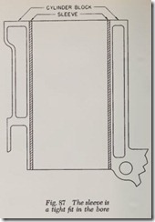
If a cylinder bore is cracked or so ba dly worn or scored that more than .060″ must be removed by reboring, a cylinder sleeve may be installed, Fig.87. The sleeve is usually made of a high grade of
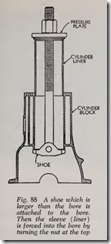
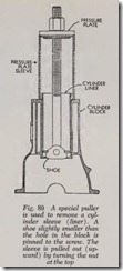
alloy cast iron. Sleeves are supplied in various thicknesses such as 1/16″, 3/32″, 1/8″ and 5/32″, the 3/32″ being the most popular. The inside diameter comes finished to standard bore size for a particular make and model of engine. The en gine is rebored to the outside diameter of the sleeve and the sleeve is pulled into position by a suitable tool, Fig. 88. Fig. 89 illustrates the m ethod of removing a worn sleeve.
“PREPARING CYLINDER BLOCK FOR
HIGH PERFORMANCE”
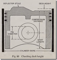
Before disassembly of components from the block , check the deck heigh t. This is the distance from the top of the piston at TDC to the top or deck surface of the cylinder block, Fig. 90. This is a critical dimension as it relates directly to the compression ratio. It must be held constant to ensure a proper balanc e of comb ustion chamber volumes when the head is installed.
Completely disassemble cylinder block, remov ing everything from it that can be removed crankshaft , camshaft, water jacke t plugs, etc., and give it a Magnaflux test to make sure that there are no cracks. Next check the main bearing bores for specified diam eter and alignment with each other.
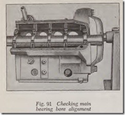
To ch eck main bearing alignment , place an arbor of the correct size in the bearings and tighten the bearing caps to the correct torque, Fig.91. If the arbor can be freely turned under this condition, the bearings are in alignment. If the arbor binds, the bearings must be line bored.
Check the deck surfaces of the block to see that they are parallel with the crankshaft axis. This must be done after the bearings are line bored. The distance from the centerlin e of the crank to the deck surface of the block must be the same at front and rear. If they are not the same, the head surfaces on the block will have to be milled or ground until they are parallel to the crank. They should be cut the least amount necessary to pro duce a true flat surface.
Remove casting burrs and slag with a small hand grinder. This helps to ensure that these protrusions, or flashings, don’t break away and close off a critical oil passage or scuff moving surfaces. The grinding operation also helps to reduce stress areas where cracks are most likely to start.
Run a bottoming tap down all bolt holes to clean out any deposits. A small chamf er on the cylinder head bolt or stud holes will prevent the top thread from pulling up when the bolts or studs are tightened down. This would prevent the cylinder head from sealing properly to the block.
Check all dowel pin heights. If any are longer than their mating holes a proper seal cannot be attained.
Polish tappet bores with fine grit sandpaper to remove rough spots.
Rough-up rear main bearing oil seal machined surface with a center punch. This helps to prevent the seal from slipping in the groove at high speed.
Run a small bottle brush or drill through all oil passages.
Check and refinish cylinder bores as required. Visually inspect the walls for scores, cracks, spotty wear, etc. Measure the bores for taper or out-of-round condition, and if required, bore the cylinders. Leave approximately .002″ stock for the honing operation.
Hone the cylinder walls to their final dimension. Honing is recommended both to remove glaze when installing new rings-or a glaze breaker can be used-and as the final step in reboring. Wet honing, with a cutting fluid, is preferable to dry honing.
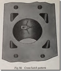
The recommended surface finish to produce the 60° pattern shown in Fig. 92, is best achieved by frequent cleaning of the stones. The rate of verti cal strokes of the hone should be increased as the speed of the hone is increased.
Break all sharp edges with a small file. (Around cylinder bore chamfers, main bearing bore cham fers, etc.)
Clean the block surface thoroughly and coat its machined surfaces with a light oil film until it is ready for assembly.
