WHAT RINGS TO USE
Eaeh piston ring maker offers a variety of ring sets for both new and worn bores. Eaeh set is designed to best serve a partieular situation as regards the eondition of the bores.
However, ring sets may be divided roughly into three kinds, as follows:
1. For perfectly reconditioned bores.
2. For bores not perfeetly reconditioned or bores wtih moderate taper-say up to .007″ or thereabouts. These sets are also preferred by some repairmen for perfeet bores on the theory that they do a better job when bores have become worn.
3. Badly worn bores with taper up to .015″ or even .020″.
Some piston ring makers ordinarily reeommend sets 1and 3.
Rings for these three kinds of bores for a three ring piston might be:
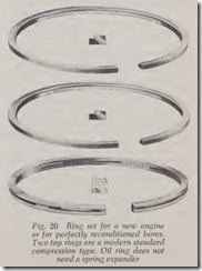
1. Two regular compression rings and one regu lar oil control ring-same as used in a new engine, Fig. 20.
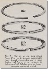
2. One regular compression ring, one more flex ible compression ring, and a more flexible oil ring, Fig. 21.
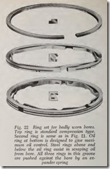
3. Same compression rings as No. 2 but a very flexible oil ring, Fig. 22.
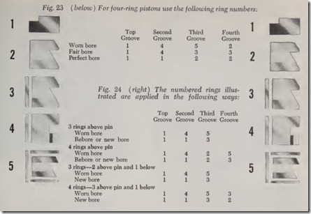
For engines with four rings above the piston pin, the rings shown in Figs. 20, 21 and 22 would be applied as shown in Fig. 23.
Ring combinations recommended by another leading ring manufacturer are given in Fig. 24.
The foregoing is offered to give the reader some idea as to the variety of sets available to meet the different conditions of bore wear.
The situation can be briefly summed up by stating that the greater the taper the more flexible the rings (except the top one) must be in order to follow the bore. The rings are contracted when at the bottom of the bore and must have the ability to expand on the up-stroke as the bore grows larger. And if the bore is out-of-round, the rings must do their best to shape themselves to the contour. This is especially important in connection with the bottom oil control ring.
The bores in a new engine may not be standard size. A car maker may produce a small percentage of engines with oversize bores-say .010″ oversize. Therefore, if the specified bore is 3.250″, som e of the bores in some engines, or all th e bores in others, may be 3.260″. Consequen tly, if a re-ring job is done on any of these engines, .010″ oversize rings should be used in every oversize bore.
Cylinders may also be oversize because they have been rebored one or more times in the past. If so, if new rings are to be installed in worn bores, select the ring oversize for th e job.
REMOV ING PISTON RINGS
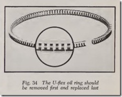
Hold the piston upright by clampin g the rod in a vise. Remove the top ring, then second, third, and fourth if there is one. All piston rings should be removed upward. Never try to slide a ring down over the piston skirt as there is danger of scratching the skirt. When replacing rings, install the bottom one first, and the top rin g last. There is one exception: A U-Flex oil ring, Fig. 34, should be removed first and replaced last.
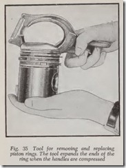
A piston ring removing and replacing tool is almost a necessity. There are num erous designs on the market. One type is shown in Fig. 35. The rin gs are likely to be distorted if removed and replaced by hand.
FITTING PISTON RINGS
Some of the rings in a set may have a top and bottom. That is, one side of the ring must be in stalled toward the head of the piston. Follow the directions included with the ring package.
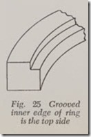
When a compression ring must be installed “right side up” it will be found that the upper inner edge is beveled or notched, Fig. 25. In other words, whenever the inner corner is modified in any way it should be on the upside of the piston.
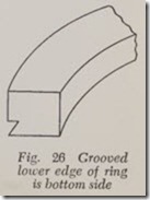
Similarly if either a compression ring or a cast iron oil ring has its lower, outer corner modified, as in Fig. 26, for example, this corner should be on the down side of the piston.
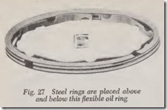
When flexible oil rings have two flat steel rings, Fig. 27, the steel rings arc usually installed above and below, as shown.
Before actually fitting the rings, of course, the pistons must be cleaned and otherwise prepared to receive them. But rather than go into the pro cedure for doing this work at this time, we leave it for later.
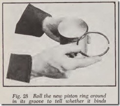
Roll each ring around in its groove, Fig. 28. If it binds, check the groove for dirt and burrs. If it bing with fine emery cloth placed on a smooth surface.
Check the rings for side clearance if this has not already been done. Also check the ring groove depth, if necessary.
The ring end gap must be checked to be sure it is sufficient. Usually it is but it is not safe to install a ring without checking the gap.
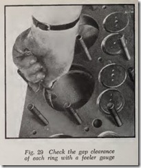
If the bores have been fully reconditioned either by a rigid hone or reboring, place the ring in the bore near the top as shown in Fig. 29. Be sure that the ring is straight across the bore by turning a piston upside down, inserting it in the bore and pushing on the ring.
If the rings are being installed in worn bores, the gap should be checked with the ring about half way down in the bore, that is, at the lower end of the ring travel where wear is least.
Check the gap with a feeler. Use the gap rec ommended by the piston ring manufacturer. But in the absence of these instructions the following table may be used:
The purpose of the gap is to allow for ring ex pansion when rings are hot. The gap must be large enough so that there is still some gap clear ance when the rings are at their hottest. The gap must never be less than the specified minimum.
But if any rings are found with less than the minimum gap the ends should be filed. Filing should be done carefully because gaps that are much too large may permit too much leakage of oil and gas pressure through the gap.
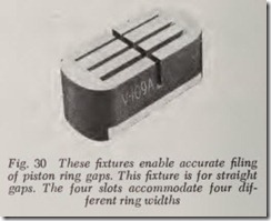
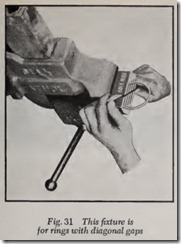
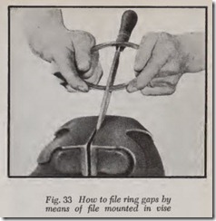
Fixtures for filing the rings are shown in Figs. 30, 31 and 32. If such a device is not available, clamp a file in a vise as shown in Fig. 33. Press the ends of the ring against the file while moving the ring slowly back and forth. Try to keep th e ends of the ring flat against the file. Check th e ring in the bore occasionally until gap is correct.
U-FLEX OIL RING
A U-Flex oil ring, Fig. 34, does n ot r equire a gap. The ends of the ring arc designed to be in contact at all times. This ring is so constructed that it is resilient around its circumf erence and therefore its cxpanison when heated is automati cally absorbed. Before installing this ring be sure it is the correct size for the bore.
INSTALL RINGS ON PISTONS
Mount the rod in a vise with the piston upright to support the piston while the rings are being put in their grooves.
A piston ring replacing tool, Fig. 35, should be used if ring distortion and breakage is to be avoided. All rings above the piston pin should be installed from bottom to top, that is, the lowest ring first and the top ring last.
If there is a ring below the piston pin, it may be installed either before or after the others.
After the rings are in place be sure they are free and do not bind. Check them by moving them laterally and also by rotating them in the grooves.
If binding exists, correct the condition before proceeding with the work.
Before installing pistons and rods in the block be sure to stagger the ring gaps. Rotate until adjacent rings are a half circumference apart. Or if preferred, space the gaps one-third revolution apart on three-ring pistons and one-fourth revolu tion apart on four-ring pistons. If the piston pin is pressure lubricated by a passage drilled in the rod, be careful that the oil ring gaps do not line up with the piston pin.
Lubricate the rings, ring grooves, piston skirts and bores with engine oil.
The last thing to do before installing a piston is to check the marks on piston and rod, so that it is correctly installed. Be careful, also, to install the piston in its correct cylinder bore.
RING COMPRESSORS
A ring compressor is essential when installing pistons in the block. A simple design is shown in Fig. 36. It consists of a steel band Hared at the upper end and contracted by the circular coil spring. It can be used only for a given bore size. The compressor is placed over the bore and the piston pushed down through it as shown.
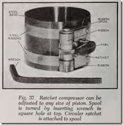
Fig. 37 shows a ring compressor that can be adjusted to the piston diameter. It consists of an overlapping spring steel band placed within two steel ribbons whose ends are attached to the clamp spool. The device is adjusted to the approx imate diameter of the piston. Then it is placed over the upper end of the piston with its top Hush with the top of the piston. Tighten the band by inserting the wrench in the square hole in the top of the clamp shaft. When rings are fully com pressed, back the ratchet off one notch. Insert the piston in the bore and tap the piston into place gently with the handle of a hammer.
