TELECOMMUNICATION SYSTEMS
Telecommunications is defined as the technology concerned with communicating at a distance. The first requirement is for the original form of energy (human voice, music, or a telegraph signal) to be converted into electrical form to produce an electronic information signal. This is achieved by a suitable transducer, a device that converts energy from one form to another. In a telephone system, the transmitted signals are replicas of the speech waveforms. Digital signals consist of discrete pulses of voltage or current which represent the information to be processed. Digital voltages can vary only in discrete steps; normally only two voltage levels are used, so that two-state devices can be employed. A two-state device has two stable states; that is either ON or OFF. An electrical switch is a two-state device; it is either ON or OFF.
TELECOMMUNICATION SYSTEMS
In a line communication system, the electronic signal is passed to the destination by a wire or cable link, with the the energy travelling at a speed of upto 60% that of light, depending on the type of line. At the destination, a second transducer converts the electronic signal back to its original form. Amplifiers may be inserted to increase the power level of signals to compensate for losses encountered. This is shown in Fig. 37.1.
For a wireless communication system, a transmitter is required at the source to send the signal over the radio link, with the energy travelling at the speed of light, and a receiver is needed at the destination to recover the signal before applying it to a transducer.
In both of these system interference will be generated by electrical noise, and distortion of the electronic signal will occur for a number of reasons. These are undesirable effects and must be minimised in the system design.
Simple single-voice band signals are unidirectional (one-way only) and generally called channels; domestic radio and television broadcast are examples of such systems.
The telephone system, however, must be capable of conveying information in both directions. To do this the basic requirements must be duplicated in the opposite direction. A pair of complementary channels provide bidirectional communication, generally called a circuit.
Equipment is available which enables more than one voice channel to be carried on a pair of wires, a coaxial cable, a radio link or an optic fibre. Such multichannel equipment is called carrier or multiplexing equipment.
Coaxial cable networks, with amplifying stations every few kilometres, now link together most of the cities in developed countries. These networks carry many thousand multiplexed channels.
Radio equipments operating at frequencies much higher than ordinary domestic radio sets are called microwave links are also able to carry thousands of multiplexed voice channels between terminals.
Optic fibres are a new and special form of transmission path in which energy representing up to two thousand voice channels can travel as pulses of light along a single glass or silica fibre comparable in diameter to a human hair. Optic fibre cable networks are now being installed in many countries making possible a huge expansion of telecommunication services.
LINE SYSTEM CHARACTERISTICS
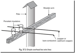
The simplest form of two-wire line is produced by using bare conductors suspended on insulators at the top of poles (Fig. 37.3). The wires must not be allowed to touch each other; this would provide a short circuit and would interrupt communications.
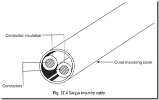
Another type of two-wire line consists of conductors insulated from each other in a cable, which also has an outer cover of insulation (Fig. 37.4). This outer sheath used to be made of lead but various types of plastic are now commonly used, particularly PVC. The two insulated conductors in the cable are often twisted together along the length of the cable and are called a pair.
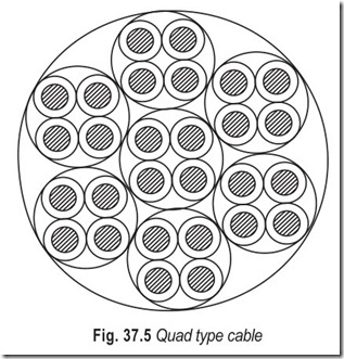
Many two-wire lines are often wanted between the same two places. These can most conveniently be provided by making a cable with a number of pairs of insulated wires inside it. Sometimes the wires are twisted together in pairs but sometimes they are provided in forms or quads as shown in Fig. 37.5.
In order to identify the various wires each wire has a colouring on the insulating material around it, in accordance with a standard colour code for cable pair identification.
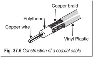
As the frequency of an alternating current is increased the current tends to flow along the outer skin of the conductor, and ordinary twin and quad type cables become inefficient. A special type of cable suitable for use at high-frequencies has therefore been developed. This has one of its conductors completely surrounded by the second one, in the form of a tube. This type of cable, called a coaxial cable is shown in Fig. 37.6. The two conductors can be insulated from each either by a solid insulant (dielectric) along the whole length of the cable or by insulating spacers fitted at regular intervals as supports for inner conductor. In this case the main insulation is the air between the two conductors.
Whatever the type of cable used, the conductors always have some opposition to current flow. This is called resistance. Furthermore no insulation material is perfect, so a very small leakage current will always flow between the two conductors, instead of all of it flowing along them to the distant end.
Also, the insulation between the conductors forms a capacitance which provides a conducting path between the conductors for alternating current. This capacitance has the ability to store electrical energy. The higher the frequency of the information signal, the more current travels across this capacitance path and the less reaches the distant end of the line.
When an electric current flow—along a wire, a magnetic field is established around the wire. Whenever the current in a wire changes, either by the switching on or off of a one way or direct current, or the repetitive changes of an alternating current, its accompanying magnetic field is made to change also, and energy is needed for these changes. This is called the inductance of the circuit.
Energy is used to make the current flow against the resistance along the conductors, and against the insulation resistance between the conductors. Energy is also used in charging and discharging the capacitance between the conductors. In multipair cables there is capacitive and inductive coupling between pairs also, so that some energy is passed from one pair to another. These losses further reduce the amount of energy that reaches the far end of the original pair and so contribute to the total loss.
In the case of an information signal, all this lost energy has to come from the signal source so that the energy available gradually decreases as the signal travels along the line. This loss of energy along the line is called attenuation. If the line is long and the attenuation is large, the received energy may be too weak to operate the receiving transducer unless some corrective action is taken.
RADIO SYSTEM CHARACTERISTICS
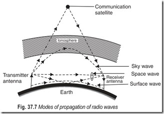
When a radio-frequency current flows into a transmitting antenna power is radiated in a number of directions in what is called an electromagnetic wave. These waves travel at the same speed as light and can be reflected and refracted just as light can be. Some antennas are designed to be highly directional, some are omnidirectional. The radiated energy will reach the receiving station by one or more of five different modes as shown in Fig. 37.7.
1. Surface wave; 2. Sky wave; 3. Space wave; 4. Via a satellite and 5. Scatter
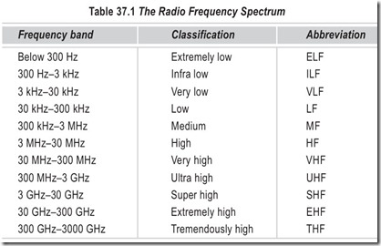
1. The surface wave is supported at its lower edge by the surface of the earth and is able to follow the curvature of earth as it travels. The surface wave is used for world-wide communications in the low-frequency bands and for broadcasting in the MF band (see Table 37.1)
2. The sky wave is directed upwards from the earth into the ionosphere (100 km or more above ground level) whence, if certain conditions are satisfied, it will be returned to earth for reception at the required locality.
3. The space wave generally has two components, one of which travels in a very nearly straight line between the transmitting and receiving locations, and the other travels by means of a single reflection from the earth.
4. The fourth method is a technique that utilises the ability of a communication satellite orbiting the earth to receive a signal, amplify it, and then transmit it at a different frequency back towards the earth.
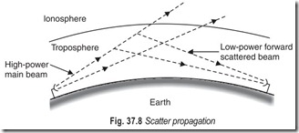
5. The fifth method, listed scatter, could be said to be the UHF/SHF equivalent of using skywave transmission for long distance HF radio links. The radio energy is directed towards part of the troposphere which forward scatters the signal towards the receiver. The scattering region of the troposphere is about 10 km above ground level (Fig. 37.8).
The radio frequency spectrum has been subdivided into a number of frequency bands, these are given in Table 37.1.
TELEPHONE RECEIVERS AND HANDSETS
Telephone receivers are electromagnetic transducers which convert telephone signals into sound pressure waves. They are made compact and of very rugged construction to withstand the abuse of telephone usage.
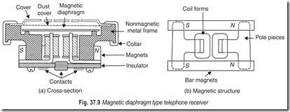
Figure 37.9 shows a compact version of the telephone receiver which was in use from the early 1920s until the late 1950s. Two small but very strong permanent bar magnets provide the magnetic bias field. This field is channeled to the diaphragm through the two formed soft iron pole pieces on which the coils are mounted as shown in Fig. 37.9. The whole magnetic structure is fastened to an aluminium frame which also supports the magnetic diaphragm, a perforated cover, and a dust cover membrane held in place by a formed aluminium collar. A fibre-board cover fastened to the back of the magnetic structure carries a contact button and a contact ring through which the electrical connections are made from spring contacts in the handset.
The magnetic bias field is necessary because if it were not present, the diaphragm would vibrate at twice the frequency of the applied signal current. A magnetic diaphragm suspended above the poles of an electromagnet with no permanent magnetic field would experience attracting force when the current through the coils was zero. The diaphragm would experience maximum attraction force when the current reached the maximum value of either polarity. Thus the diaphragm would be pulled in twice during each cycle of the applied signal current. With a permanent magnetic field component present, the diaphragm always experiences a positive attraction force. With maximum positive signal, the force would be twice the zero signal force, and with maximum negative signal the force would approach a zero value. The diaphragm would thus oscillate around its bias position at the same frequency as the signal current.
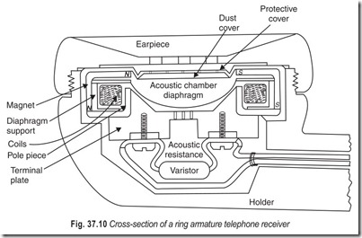
The receiver described above has been almost entirely replaced by a different version, called ring armature receiver which was introduced in 1950s. Figure 37.10 shows a cross-section of such a receiver unit. In this unit the heavy magnetic diaphragm is replaced by a very lightweight dome shaped diaphragm made of aluminium which is fastened to a ring-shaped disk of magnetic material which forms the armature. The magnetic structure is formed by a cylindrical permanent magnet with an L-shaped cross-section and an L- shaped cylindrical soft iron pole piece attached to it. The driving coil is wound inside this magnetic structure, and the ring-shaped armature is suspended in the gap between the magnet and the pole piece supported by a non magnetic support ring. A bakelite backplate provides support for the screw terminals to the coil, and also provides an acoustical resistance chamber to damp oscillations of the diaphragm. In service a bilateral varistor diode is connected between the terminals to clip off or limit high amplitude voice pulses which may be generated by switching equipment. The acoustical chambers in front of and behind the diaphragm are carefully designed so that the mechanical resistance encountered by the diaphragm closely matches the electrical impedance of the telephone circuit. A perforated protection cover and a dust membrane are crimped around the top of the unit and the whole unit is mounted inside the ear piece of a handset. Typical terminal impedances range from 100 to 2000 Ω.
SIGNALLING
In telephony context signalling means the passing of information and instructions from one point to another relevant to the setting up or supervision of a telephone call. To initiate a call a telephone subscriber lifts the handset off its rest-goes off hook. This off hook state is a signal to the exchange to be ready to receive the number of the called subscriber. As soon as appropriate receiving equipment has been connected to the line,
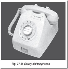
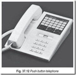
the exchange signals dial tone back to the calling subscriber who then dials the wanted number. On older exchanges, this information is passed by a rotary dial (Fig. 37.11) by a series of makes and breaks of the subscriber’s loop interrupting current flow. On more modern exchanges, voice frequency musical tones are sent to the exchange as push buttons (Fig. 37.12) are pressed. These tones are usually called DTMF (Dual Tone Multi Frequency), because each time a button is pressed two tones are sent out of line simultaneously, one from a set of four high-frequencies, one from a set of four low-frequencies. The subscriber in due course then receives advice from the exchange about the status of the call, either a ringing signal (indicating that the wanted line is being rung), an engaged or busy tone signal (indicating that the wanted line is already busy on another call), an equipment busy tone signal (indicating congestion somewhere between the called exchange and the calling line) or some other specialised tone. These are signals and tones with which telephone subscribers themselves are concerned. Telephone signalling is however also concerned with the signalling of information between exchanges.
CCITT NO. 7
Until recently all such signalling was carried on or directly associated with the same speech path as was to be used for the call being established or supervised. Various terms are commonly used in connection with these speech-path-associated signalling systems.
(a) MF: Multi-frequency, i.e. using voice frequency tones.
(b) MFC: Multi-frequency compelled : this type of signal continues until the distant end acknowledges receipt and compels it to stop.
(c) 1 VF: One voice frequency : a single tone, sometimes pulsed in step with rotary dial impulses.
2600 Hz is a common 1VF tone.
(d) 2 VF: Two voice frequencies : two tones, sometimes used together, sometimes separately
(e) In band: A tone actually on the voice circuit itself, audible to any one using the circuit (and so cannot be used during conversation).
(f) Outband: Signals directly associated with a voice circuit but either carried on separate wires or using a different frequency , just outside the commercial speech band of 300–3400 Hz. A frequency of 3825 Hz is often used for outband signalling.
All of these signalling systems have a number of limitations :
(a) Relatively slow.
(b) Limited information capacity.
(c) Limited capability of conveying information which is not directly call related.
(d) Inability of some systems to send detailed information back to the calling end.
(e) Inability of some systems to provide sufficient information for accurate itemised call billing.
(f) Systems tend to be designed for specific application conditions.
(g) Systems tend to be expensive because each circuit has to be equipped independently; there are no sharing techniques and no economies of scale.
The increased use of computer controlled (or SPC, stored program control) exchanges has led to the introduction of a completely different signalling concept. Instead of signalling being carried on, or directly associated with, the voice channel carrying the conversation, there is now a move towards signalling being concentrated onto fast data circuits between the processors of the SPC exchanges concerned leaving the voice circuits purely to carry voice signals. Signalling for several hundred long-distance circuits can be carried by a single fast data system, and substantial economies result.
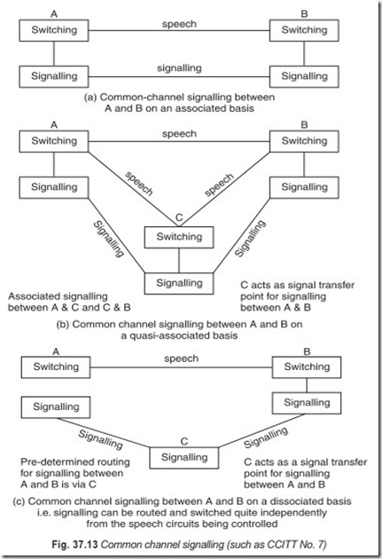
A signalling system of this type has now been standardised by the body responsible for drawing up specifications for international use; this is called CCITT Signalling System No. 7. CCITT means the International Consultative Committee for Telephony and Telegraphy. No. 7 signalling (Fig. 37.13), has not only been designed to control the setting up and suspervision of telephone calls but of non-voice services also such as word processors, teletext machines etc. With Common Channel Signalling (CCS) systems, such as CCITT No. 7, signalling is performed in both directions, with one signalling channel in each direction. This type of signalling has several attractive features :
(a) Signalling is completely separate from switching and speech transmission, and thus may evolve without the constraints normally associated with such factors.
(b) Significantly faster than voice-band signalling.
(c) Potential for a large number of signals.
(d) Freedom to handle signals during speech.
(e) Flexibility to change or add signals.
(f) Potential for services such as network management, network maintenance, centralised call accounting.
(g) Particularly economical for large speech circuit groups.
(h) Economical also for small speech circuit groups due to the quasi-associated and dissociated signalling capabilities (sec Fig. 37.13).
(i) Systems have been standardised for international use.
(j)Can be used to control the setting up and supervision of non-voice services and so will be important for ISDN.
A common channel signalling system providing signalling for many speech circuits must have a much greater dependability than on-speech-path signalling since random errors could disturb a large number of speech circuits. For this reason provision must be made to detect and correct errors. Additionally, automatic re-routing of signalling traffic to a good backup facility must occur in a situation of excessive error rate or on failure of a signalling link.
MODES OF OPERATION
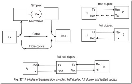
It would be a good idea to look at some overall systems. Transmitters and receivers are tied together in a number of ways that describe the kind of system rather than the kind of transmitting format used. One of the first questions to come to mind is : In how many directions will the data be transmitted ? This can best be answered by defining the classifications of systems we use today (see Fig. 37.14).
1. Simplex (SPX) : Information can be sent in only one direction. Commercial radio and television use this mode. They transmit, and you receive. You can never interact by the same communications link, regardless of how the signal reaches your receiver (RF transmission or cable).
2. Half duplex (HDX) : Information can be sent in both directions, but not at the same time. Citizens band or ham radio are prime examples. The operator must press a control to transmit and release the control to receive. In the transmit mode the receiver is disabled, and in the receiver mode the transmitter is disabled.
3. Full duplex (FDX) : Information can be sent in both directions at the same time without interference.
The telephone is probably the best example. Both parties may talk at the same time and each is able to hear the other.
4. Full/full duplex (F/FDX) : This is the latest mode to be developed. It describes a unit that is able to receive a message from one remote station while it is transmitting a different message to a third station. Machines are able to carry on two or more conversations at the same time.
Although RF signals are used in these examples, most of the world’s land communications are handled by the interconnecting network of telephone companies. The same definitions hold regardless of which route is taken. In RF transmission, when the system has one carrier frequency the land line has one twisted wire pair. When the RF system uses two different frequencies, the land line has two twisted wire pairs as would be required for FDX.
STATION INTERCONNECTIONS
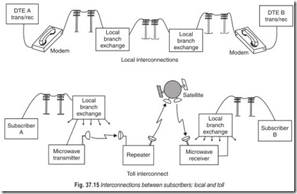
The majority of digital traffic is processed through the telephone networks (see Fig. 37.15). An outgoing message is carried through twisted wire pairs to the local branch exchange, then to the receiver’s local branch exchange, and finally to the subscriber’s receiver. Long distance interconnections go from, the transmitter’s local branch exchange to a toll exchange, from there to the destination toll exchange, then to the subscriber’s branch exchange, and then to the subscriber’s receiver.
Depending on the distance between the stations, the message may undergo any number of modulation and demodulation processes, including satellite links and fibre optic cabling, without the knowledge of the transmitter or receiver. Since the telephone company systems are almost all automatic the equipment will pick the route of the interconnection that is open at the time of call origination.
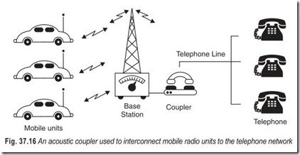
Such interconnection systems are used for what the phone company calls dial uplines. These are the same lines that are used for the home phone. The sender uses a standard telephone to dial the number of the receiver and then places the hand set of the phone into an acoustical coupler attached to the transmitting digital terminal. The equipment is compensated for the data speed the telephone company is able to handle.
When high data rates are a requirement, arrangements can be made for special routing, which the subscriber pays for on a leased basis. These lines are called private or dedicated lines. The subscriber may request a hard copper connection, which means that there will be no switches or transformers in the line between the transmitter and the receiver.
The above description applies to serial code transmission, using a two-wire or four-wire interconnection, but could also apply to parallel code transmission, where eight wires would be required for an eight-digit transmission. The tradeoffs between serial and parallel transmission in the distance between stations and daily leasing costs.
THE RS232C INTERCONNECTING CABLE
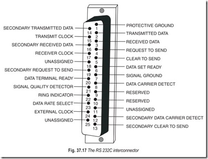
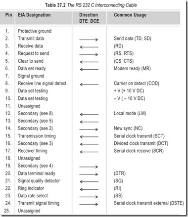
Because of the growing number of computer manufacturers, it became necessary to establish a fixed arrangement of interconnecting computers to match the connections of any unit with the connections of any other units. The solution became known as the 232C inter connecting cable (Fig. 37.17 and Table 37.2).
The RS 232 C generated by Electronic Industries Association, does not concern itself with the content or makeup of the serial data. Rather, it attempts to define polarity (or direction) and level of signals, as well as the interfacing of RS 232 C devices.
TTL levels are used extensively inside a computer. Most computers have a 5 V supply which powers all the TTL circuits. However, TTL is not intended to be run through wires for any great distance. Outside electrical interference, in particular, can mess up a TTL-level signal traveling within a wire cable. For example, let’s say a serial printer in an office is 30–50 feet away from the computer. In this environment, interference from electrical cords and machines can scramble the digital data if TTL levels were used.
The makeup of a single digit byte, under the RS 232 C specification is shown in Fig. 37.18. A digital one is a minus voltage while a zero is a positive voltage. There is a no man’s land between minus three volts and plus three volts, in other words, a digital one must be more negative than minus three volts, while a digital zero must be more positive than plus three volts. Thus, the polarity of an RS 232 C bit is just the opposite of TTL. Also the total amplitude is more than the five volt maximum found in TTL circuits. To meet the RS 232 C specification, the total amplitude must be at least six volts to go above and below the dead zone.
The purpose of this six-volt zone is noise protection. Static which might be coupled into the RS 232 C cable must exceed at least three volts before it will foul up the digital data. Such noise levels are not very likely even in the presence of strong electrical noise.
EXERCISES
Descriptive Questions
1. Differentiate between a wireless and a line communication system.
2. What are the characteristics of a wireless communication system?
3. What are the characteristics of a line communication system?
4. Briefly explain the following terms:
(a) Interference (b) Unidirectional and bidirectional channels
(c) Multiplexed channels (d) Microwave links
(e) Coaxial cable (f) Attenuation
(g) Modes of propagation of (h) Scatter propagation radio waves
5. Give examples of electromagnetic transducers. With the help of a suitable diagram explain the working of a ring-armature receiver.
6. What are the attractive features of common channel signalling (CCS)?
7. What are the classes of communication systems? Give examples.
8. How telephone networks are interconnected?
9. Explain the following terms:
(a) Local (b) Toll
(c) Acoustic coupler (d) Modem
10. Briefly explain the RS 232 C interconnecting standard. Why is it required?
Fill in the Blanks
1. Interference and distortion are …………………. effects.
2. Coaxial cable networks carry many thousand…………………. channels.
3. The two insulated conductors in the cable are often twisted together along the length of the cable, and are called a…………………. .
4. There is a standard colour code for cable pair…………………. .
5. In the case of an information signal, all the lost energy has to come from the…………………. .
6. The surface wave is able to follow the…………………. of the earth as it travels.
7. The skywave is directed upward into the…………………. .
8. The scattering region of the…………………. is about 10 km above ground level.
9. Typical terminal impedances range from…………………. to…………………. .
10. To initiate a call a telephone subscriber goes…………………. .
11. In DTMF each time a button is pressed…………………. are sent out to the line simultaneously.
12. In a CCS system provision must be made to…………………. errors.
13. In a simplex system, information can be sent in…………………. .
14. In a half duplex system, information can be sent in both directions but…………………. .
15. In a full duplex system, information can be sent in…………………. at the same time.
ANSWERS
Fill in the Blanks1. undesirable |
2. multiplexed |
3. pair |
|
4. identification |
5. signal source |
6. curvature |
|
7. ionosphere |
8. troposphere |
9. 100Ω, 2000Ω |
|
10. off hook |
11. two tones |
12. detect and correct |
|
13. only one direction |
14. not at the same time |
15. both directions |


