MODULATION TECHNIQUES
Over the years modulation methods have been devised for transmitting the required information as effectively as possible with the minimum amount of distortion. The primary factors to be considered are signal power, bandwidth, distortion and noise power. Ultimately, it is the ratio of signal power to noise power or output signal to noise ratio specified for the system which determines its performance.
Consequently, it is not surprising to find a wide range of modulating techniques being used which appear to compete with one another under given practical conditions. Broadly speaking, these various techniques may be grouped into analog methods which use a sine wave as the carrier signal and pulse method which use a digital or pulse train as the carrier signals.
ANALOG METHODS
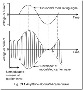
The two most important analog methods are amplitude modulation and angle modulation. Amplitude modulation (AM) with both sidebands and carrier present is most common for certain application, such as radio broadcasting and radio telephony (see Fig. 39.1).
More economical versions of AM are vestigial sideband transmission (VSB) which is used in television for economising bandwidth, while double sideband suppressed carrier (DSBSC) or single sideband suppressed carrier (SSBSC) provide further power or bandwidth economy. In particular, SSBSC is used extensively in multiplex coaxial systems for carrying several messages simultaneously. However the AM systems are essentially narrowband systems and suffer from limitations due to noise which has a direct effect on signal amplitude.
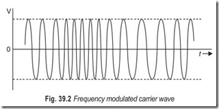
Some systems use angle modulation because of its immunity to amplitude-varying noise. In angle modulation, the instantaneous angle of the carrier wave is varied and this leads to two forms of modulation known respectively as frequency modulation (FM) and phase modulation (PM). As a consequence, FM and PM are closely related though practical systems tend to favour FM rather than PM Typical examples are VHF communication, satellite communication and FM radar. However, because the FM carrier wave, shown in Fig. 39.2, requires a much greater bandwidth than its AM counterpart, an FM system is capable of giving a much improved signal to noise performance compared to that of the corresponding AM system or, alternatively, a considerable economy on power, if required. Hence, FM systems are to some extent superseeding AM systems.
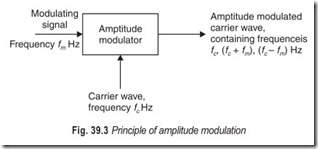
Amplitude modulation : A bandwidth of 300 to 3400 Hz is required for the transmission of commercial quality speech. To economise on cable it is desirable to be able to transmit more than one conversation over a single pair of wires. If several conversation signals were all connected together at one end of a line, it would not be possible to separate them at the distant end since each conversation would be occupying the same frequency spectrum of 300 Hz to 3400 Hz. Amplitude modulation (AM) plus frequency division multiplexing (FDM) is one way of solving this problem. Each conversation is shifted to a different part of the frequency spectrum by using a high-frequency waveform to carry each individual speech signal. These high-frequencies are called carrier frequencies.It can be shown that, when a sinusoidal carrier wave of frequency fcHz is amplitude modulated by asinusoidal modulating signal of frequency fmHz, then the modulated carrier wave contains three frequencies:the original carrier frequency, fcHz, the sum of the carrier and modulating frequencies (fc+ fm ) Hz and thedifference between carrier and modulating frequencies, (fc – fm ) Hz. This is illustrated in Fig. 39.3.
Two of these frequencies are new, being produced by the amplitude modulation process, and are called side frequencies : the upper side frequency (sum) and the lower side frequency (difference). The bandwidth of the modulated carrier wave is (fc + fm) – (fc – fm) = 2fm, i.e. double the modulating signal frequency.
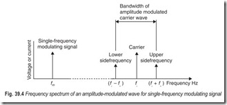
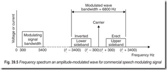
When the modulating signal consists of a band of frequencies, then each individual frequency will produce upper and lower side-frequencies about the unmodulated carrier frequency and so upper and lower sidebands are obtained. This is shown in Fig. 39.4.
As the modulating signal bandwidth increases, the modulated wave bandwidth also increases, and the transmission system must be capable of handling this bandwidth throughout. All the information is carried by either one of the sidebands. The carrier component is of constant amplitude and frequency and hence does not carry any of the information signal at all.
It is possible by using special equipment to suppress both the carrier and one sideband and to transmit just the other sideband with no loss of information. This is called single sideband working (SSB) or single sideband suppressed carrier working. This method is complex and costly and hence it is not used for domestic radio broadcasting but it is used for some long-distance radio telephony systems and for multi-channel carrier systems used in national telephone networks.
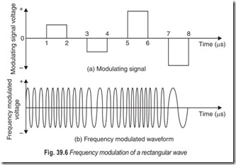
Frequency Modulation : Another method of superimposing information signals on to a carrier is frequency modulation in which the modulating signal varies the frequency of a carrier wave. The concept of FM can best be understood by considering a modulating signal of rectangular waveform such as the one shown in Fig. 39.6. Suppose the unmodulated carrier frequency is 3 MHz. The periodic time of the carrier voltage is 1/3 µs and so three complete cycles of the unmodulated carrier wave will occur in 1 µs. When after 1µs, the voltage of the modulating signal increases to +1 V, the instantaneous carrier frequency increases to 4 MHz. Hence in the time interval 1 µs to 2 µs, there are four complete cycles of the carrier voltage. After 2 µs the modulating signal returns to 0 V and the instantaneous carrier frequency falls to its original value, 3 MHz. During the time internal 3 µs to 4 µs, the modulating signal voltage is –1 V and the carrier frequency reduces to 2 MHz; this means that two cycles of the carrier voltage occur in this period of time. When, after 4 µs, the modulating voltage is again 0 V, the instantaneous carrier frequency is restored to 3 MHz. At t = 5 µs, the modulating voltage is +2 V and, since frequency deviation is proportional to signal amplitude, the carrier frequency is deviated by 2 MHz to a new value of 5 MHz. Similarly, when the modulating signal voltage is – 2 V, the deviated carrier frequency is 1 MHz. At all times the amplitude of the frequency modulated carrier wave is constant at 1V, and this means that the modulation process does not increase the power content of the carrier wave.
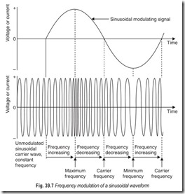
When the modulating signal is of sinusoidal waveform, the frequency of the modulated carrier wave will also vary sinusoidally as shown in Fig. 39.7. There is no inherent maximum value of the frequency deviation that can be obtained in a frequency-modulation system, this should be compared with amplitude modulation where the maximum amplitude deviation possible corresponds to 100% modulation i.e. reduction of the amplitude of the envelope to zero (see Fig. 39.1).
FM has a number of advantages over AM. The price which must be paid for some of the advantages of FM over double sideband AM is a wider bandwidth requirement. FM is used for sound broadcasting in the VHF band, for the sound signal of television broadcasting, for some mobile systems, and for multi–channel telephony.
DIGITAL METHODS
A form of modulation which uses a digital data signal to modulate a sine-wave carrier is called digital modulation. The three types mainly used are amplitude-shift keying (ASK), frequency-shift keying (FSK) and phase-shift-keying (PSK). They correspond approximately to AM, FM, and PM and are used especially in data communication systems.
ASK : On/off keying is the earliest modulation method. A continuous radio frequency wave (CW) is interrupted in a recognizable pattern (Morse code). To provide audibility the carrier is heterodyned with a beat frequency oscillator (BFO) in the receiver. The use of a modulated continuous wave (MCW) eliminates the need of a BFO but the bandwidth of the signal is increased. The problem with on /off keying is the lack of a reference level. If the signal strength temporarily falls below the sensitivity threshold of the receiver it appears to the operator as a series of spaces.
Binary Amplitude Shift Keying (BASK) : This shifts the level of an audio frequency subcarrier which then modulates a radio frequency carrier. Because the level of a subcarrier is changed, AM sidebands are produced. Also, because the keyed waveform is non-sinusoidal harmonics occur. The occupied sub-carrier bandwidth for ASK is:
Bandwidth = 2B …(39.1)
where B is the bit repetition rate (bits/second).
When the RF carrier is modulated its bandwidthis 2 (fc + B) where fc is the subcarrier frequency.
FSK : Although used for conveying digital information, frequency shift keying in reality employs frequency modulation. In its original form, developed for HF frequency transmission, FSK changes the carrier frequency to indicate a 1 or 0 but retains the nominal carrier frequency as a reference and to represent a mark. A downward shift of carrier frequency by 170 Hz represents a space in the HF radio system.
Modern FSK uses two different modulation frequencies to represent 1s and 0s. If the intersymbol interference (ISI) is to be avoided the separation of the tones must be more than half the bit rate, and a factor of 0.7 is often used.
The base bandwidth requirement is :
Bandwidth = f2 – f1 + 2B …(39.2)
The bandwidth of a modulated carrier is :
RF bandwidth = 2 (f2 + B) … (39.3) (narrow band FM)
Minimum shift keying is a form of FSK where the frequency deviation is equal to half the bit rate.
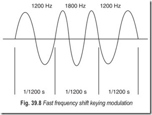
Fast Frequency Shift Keying (FFSK) may either amplitude or frequency modulate the carrier. In binary FFSK, the data is changed in a modem to tones of 1800 Hz to represent binary 0 and 1200 Hz to represent binary 1. During transmission a binary 1 consists of 1 cycle of 1200 Hz, and a 0 consists of 1½cycles of 1800 Hz (f1and f2 ) i.e. a bit rate of 1200 bps. For acceptable intersymbol interference the distancebetween the tones cannot be less than half the bit rate and the 600 Hz separation in FFSK represents the fastest signalling speed—hence the description—and minimum bandwidth. For this reason it is sometimes called minimum frequency shift keying (MFSK). The base bandwidth is the same as for FSK, but the RF bandwidth depends upon the system deviation.
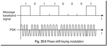
PSK : There are several variants of phase shift keying. Binary phase shift keying changes the phase of the carrier by 180° at the zero crossing point (Fig. 39.9). No carrier frequency is present with PSK as half the time the carrier is multiplied by + 1 and the other half by –1 and cancels out, but the reference phase of the carrier must be re-inserted at the receiver. The bandwidths occupied are the same as for ASK i.e.
Baseband = 2B
RF bandwidth = 2(fc + B)
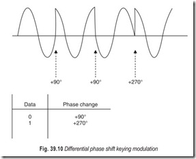
Differential phase shift keying (DPSK) advances the phase by 90° or 270° at each change of logic state (Fig. 39.10). Changing phase only at a change of logic state saves bandwidth which, for DPSK, is equal to the bit rate.
An important advantage of both FFSK and PSK over FSK is that because the moment of change is predefined, it is possible to recover data more accurately. However, the transition between signalling states is not smooth requiring large and rapid phase shifts. Multilevel systems with less phase shift between elements are preferable.
PULSE METHODS
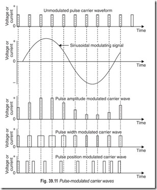
An alternative method of modulation uses a digital carrier signal comprising a pulse train which can be modulated to carry the required information. The amplitude, width or position of the pulses can be altered by the information signal as shown in Fig. 39.11. Pulse amplitude modulation (PAM) is that form of modulation in which the amplitude of the pulse carrier is varied in accordance with some characteristic, normally the amplitude, of the modulating signal. Pulse width modulation (PWM) is that form of modulation in which the duration of a pulse is varied in accordance with some characteristic of the modulating signal. Pulse position modulation (PPM) is that form of modulation in which the positions in time of the pulses are varied in accordance with some characteristic of the modulating signal without a modification of pulse width.
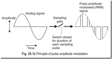
Pulse Code Modulation (PCM) : In a PCM system the analog signal is sampled at regular intervals to produce a pulse amplitude modulated waveform. If an analog signal is sampled regularly using a sampling rate of atleast twice the highest frequency of the signal, the samples are found to be adequate to allow the re- creation of the original voice signal with sufficient accuracy for all practical purposes. Sampling is done by feeding the analog signal to a circuit with a gate which opens only for the duration of the sampling pulse. The output is a pulse amplitude modulated (PAM) signal. This is shown in Fig. 39.12.
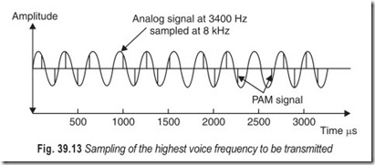
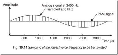
Figures 39.13 and 39.14 show the effect of taking these samples from sound signals of different voice frequencies. Although the commercial voice band goes upto 3400 Hz, almost all the power of human speech is at much lower frequencies (for example at around 500 Hz for male voices) so several samples are taken during each cycle, enough to enable the original analog signal to be reconstituted with a fair degree of accuracy.
The total amplitude range that the signal may occupy is divided into a number of levels, each of which is allocated a number. There are 256 different levels in internationally recommended PCM.
There are two different PCM encoding laws in use in the world, called µ-law coding (developed and used in America) and A-law coding (developed and used in Europe). These two laws give different quantization values for a signal of a given amplitude so that PCM channels to these two standards cannot directly interwork unless special interfacing equipment is provided.
The variable-amplitude PAM signal is then compared with the instantaneous value of the appropriate range of levels which are called quantizing intervals. The signal is assigned the value of the interval in which it falls and the number of this value is then encoded into an 8 digit binary code. This gives 28 or 256 possible levels, 128 each side of zero. Each 8 digit code describing the amplitude level of the sample is known as a PCM word. Since the sampling rate is 8000 times per second and each sample has 8 digits, there are 64000 bits per second for a single PCM channel.
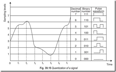
Fig. 39.15 shows how this quantization process works for a complex analog signal. Only 8 sampling levels are shown for clarity; these 8 levels require only 3 binary digits against the 8 binary digits needed to distinguish between the 256 levels used is practical PCM system.
The signal waveform is sampled at time instants t1 , t2 , t3 etc. At time t the instantaneous signal amplitude is in between levels 5 and 6 but since it is nearer to level 6, it is approximated to this level. At instant t2 the signal voltage is slightly greater than level 6 but is again rounded off to that value. Similarly the sampletaken at t3 is represented by level 2, the t4 sample by level 2, the t5 sample by level 1, and so on. The binarypulse train which would be transmitted to represent this signal is shown in Fig. 39.16. A space, equal in duration to one binary pulse, has been left in between each binary number in whichsynchronisation information can be transmitted.
A PCM system transmits signal information in digital form. The quantization process will result in some error at the receiving end of the system when the analog signal is reconstituted. The error appears in the form of quantization noise and can be reduced only by increasing the number of sampling levels. This would increase the number of binary digits required and the bandwidth which must be provided would be wider. Practical systems have to accept a compromise solution. With an 8 binary digit scheme, the quantization noise is generally considered acceptable.
For the receiving equipment to be able to decode the incoming binary pulse trains, it is only necessary for it to be able to determine whether or not a pulse is present. The processes of encoding and quantizing are reversed: a replica of the PAM signal is first generated, then this is fed to a low pass filter to reconstruct the original analog signal.
MULTIPLEXING
All transmission media have capacities great enough to carry more than one voice channel. In other words, their bandwidths are considerably greater than the 3 kHz needed for transmitting the human voice. At the top end of the scale microwave and fibre-optic circuits carry thousands of voice channels; at the lower end of the scale, each voice channel may be split into 12 or 24 telegraph channels.
Where a facility is set up, such as a chain of microwave links, which has a broad bandwidth it is very desirable to make the maximum use of this bandwidth by making it carry as many channels as possible. It is often desirable to construct a communication link with as wide a bandwidth as possible and then divide the bandwidth between as many users as possible. Many separate signals are multiplexed together so that they can travel as one signal over a high bandwidth.
In a multiplex system, two or more signals are combined so that they can be transmitted together over one physical cable or radio link. The resulting combined signal is transmitted over a system with a suitably high bandwidth. When it is received, it must be split up into the separate signals of which it is composed.
The word multiplexing, in general, means the use of one facility to handle several separate but similar operations simultaneously. In telecommunication language it means the use of one telecommunication link to handle several channels of voice or data. Multiplexing is possible because the operations that are multiplexed take place at a considerably slower speed than the operating speed of the facility in question. Multiplexing is a key factor in effectively utilising existing telecommunication links.
Communication channels are normally grouped together in packages that fill the bandwidth available on different types of plant. High capacity links can be created by multiplexing large numbers of channels that were, themselves, grouped together stage by stage. The original signal may go through many multiplexing stages and equivalent demultiplexing. It is thus worked upon by a variety of electronic conversion processes before it ultimately arrives at its destination.
There are three methods of transmitting more than one signal over one path: space division multiplexing, frequency division multiplexing and time division multiplexing. Space division multiplexing means that more than one physical transmission path are grouped together. Wire-pair cables, for example, are constructed containing many hundreds of wire pairs. Coaxial cables contain 20 or so tubes, giving a high total bandwidth. Frequency division multiplexing and time division multiplexing are alternate techniques for splitting up a single physical path. The quantity of information that can be carried is proportional to the range of frequencies (the bandwidth) used and to the period of time used. If the quantity of information required from one channel is less than that which the physical facilities can carry, then the space available can be divided up either in frequency slices, or time slices.
In either case, the engineering limitations of the devices employed prevent the slices from being packed tightly together. With frequency division a guard band is needed between the frequencies used for separate channels, and with time division, a guard time is needed to separate the time slices. If the guard bands or guard times were made too small, the expense of the equipment would increase out of proportion to the advantage gained.
CONCENTRATORS AND MULTIPLE ACCESS
When a fixed number of facilities are available for use they can be assigned to users in a fixed or variable manner. In today’s telephone systems, the local loops are normally assigned on a fixed basis, and the trunks are assigned on a variable basis. The trunks are therefore used much more efficiently than the local loops.
Suppose that there are 100 subscribers in a locality who use their telephones occasionally. There is, in theory, no need for 100 channels to connect them to their local switching office. Twenty channels, for example, could be used with some means of allocating a channel to a subscriber when he needs it. This technique is called concentration. There are various ways in which it can be done; hence there is a variety of devices called concentrators.
There is a fundamental difference between concentration and multiplexing. With multiplexing all subscribers can have a channel simultaneously if they want one. With concentration they cannot. In the above example if all 20 channels are in use and a twentyfirst subscriber requests a channel, he will be unlucky. He either receives a busy signal or must wait until a channel becomes free. Such is the nature of concentration. It takes advantage of the fact that not all the users are active all the time.
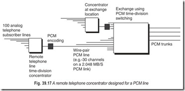
The design of a concentrator depends on the type of signal it is to concentrate. A concentrator for telephone lines may be an electromechanical device that scans a bundle of lines searching for a free one. It may be a solid state circuit that concentrates PCM traffic to travel over a digital trunk.
When a large number of locations are to be interconnected, switching offices are used to lower the number of links that are required. When high capacity channels are available at reasonable cost, there is an alternative to switching offices. Many geographically dispersed access points could share the same channel, with a control mechanism to enable them to intercommunicate as they need.
High capacity channels—such as the PCM links, digital radio, CATV cables, optical fibres and satellites are available. If they are analog channels, they can be shared by frequency division. If they are used in a digital fashion, they can be shared by time-division. Most telephone trunks are shared by point-to-point multiplexing. If there are many access points rather than two, the technique is referred to as multiple access. If it is done in a digital time-division fashion, it is called time-division multiple access, generally referred to as TDMA.
Frequency-division multiple access, FDMA, is also used. Frequency division implies that separate frequencies are allocated to different users, as in radio broadcasting; a transmitter or receiver must be tuned to the frequency that is assigned to it. Time division implies that different time slots are allocated to different users, and each user must know at what times he must transmit and receive.
TWO-CHANNEL TDM SYSTEM
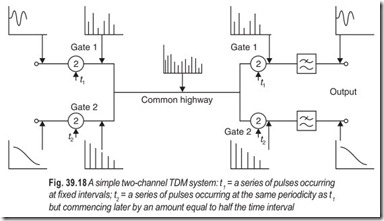
The principle of a simple two-channel TDM system is illustrated in Fig. 39.18. Analog inputs are considered for clarity. TDM is, of course, normally a means of multiplexing digital signals, such as PCM pulses, all having the same amplitude.
The two channels, which are to share the common circuit, are each connected to it via a channel gate. The channel gates are electronic switches which permit only the signal present on a channel to pass when opened by the application of a controlling pulse. Hence, if the controlling pulse is applied to gate at time t2 , and not to gate 2, gate 1 will open for a time equal to the duration of the pulse but gate 2 will remain closed. During this time, therefore, a pulse or sample of the amplitude of the signal waveform on channel 1 will be transmitted to line. At the end of the pulse, both gates are closed and no signal is transmitted to line. If now the controlling pulse is applied to gate 2 at a latter time (see Fig. 39.18), gate 2 will open and a sample of the signal waveform on channel 2 will be transmitted to line. Thus if the pulses applied to control the opening and closing of gates 1 and 2 are repeated at regular intervals, a series of samples of the signal waveforms existing on the two channels will be transmitted.
At the receiving end of the system, gates 1 and 2 are opened, by the application of control pulses, at those instants when the incoming waveform samples, appropriate to their channel, are being received. This requirement demands accurate synchronisation between the controlling pulses applied to the gates 1, and also between the controlling pulses applied to the gates 2. If synchronisation signals are sent from one end to the other as an integral component of the PCM system (as they are with internationally specified systems), all the signals will, of course, maintain their correct relative positions. If the pulse synchronisation is correct, the waveform samples are directed to the correct channels at the receiving end. The received samples must then be covered back to the original waveform, i.e. demodulated.
In its passage along a telephone line, the TDM signal is both attenuated and distorted but, provided the receiving equipment is able to determine whether a pulse is present or absent at any particular instant, no errors are introduced. To keep the pulse waveform within the accuracy required, pulse regenerators are
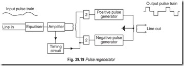
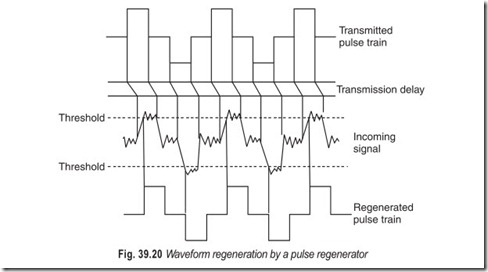
fitted at intervals along the length of the line. The function of a pulse regenerator (Figs. 39.19 and 39.20) is to check the incoming pulse train at accurately timed intervals for the presence or absence of a pulse. Each time a pulse is detected, a new undistorted pulse is transmitted to line and, each time no pulse is detected, a pulse is not sent.
In Fig. 39.19 the bit stream is first equalised and then amplified to reduce the effects of line attenuation and group-delay/frequency distortion. The amplified signal is applied to a timing circuit which generates the required timing pulses. These timing pulses are applied to one of the inputs of two-input and gates, the phase-split amplified signal being applied to the other input terminals of the two gates. Whenever a timing pulse and a peak (positive or negative) of the incoming signal waveform occur at the same time, an output pulse is produced by the appropriate pulse generator. It is arranged that an output pulse will not occur unless the peak signal voltage is greater than some pre-determined value in order to prevent false operation by noise peaks. The use of pulse regenerators allows very nearly distortion free and noise free transmission regardless of the route taken by the circuit or its length.
EXERCISES
Descriptive Questions
1. Briefly explain the analog methods of modulation.
2. Differentiate between AM and FM.
3. Explain the relative advantages and disadvantages of FM over AM.
4. With the help of a suitable sketch explain the frequency spectrum of an amplitude modulated wave for single-frequency modulating signal.
5. What are the digital methods of modulation? Explain briefly.
6. Differentiate between ASK, FSK, and PSK.
7. What are the pulse methods of modulation? Explain briefly.
8. Describe the process of quantization of a signal.
9. Why multiplexing is required? How is it achieved?
10. Differentiate between SDM and TDM.
11. Explain the difference between concentration and multiplexing.
12. How pulse regeneration is achieved?
Fill in the Blanks
1. VSB transmission is an ………………………….. version of AM.
2. AM systems are………………………….. band systems.
3. AM systems suffer from limitations due to………………………….. .
4. Noise has a………………………….. effect on signal amplitude.
5. An FsM system give a much improved………………………….. performance as compared to an AM system.
6. Frequency division is proportional to signal………………………….. .
7. The FM process does not increase the………………………….. content of the carrier wave.
8. FM systems are………………………….. band systems.
9. The problem with on/off keying is the lack of a………………………….. .
10. If inter-symbol interference is to be avoided, the separation of the tones must be more than………………………….. the bit rate.
11. 600 Hz separation in FFSK represents the………………………….. signalling speed.
12. In PSK, the reference phase of the carrier must be………………………….. at the receiver.
13. Changing phase only at a change of logic state………………………….. bandwidth.
14. Multiplexing means the use of one facility to handle several separate but similar operations ………………………….. .
15. With frequency division a guard………………………….. is needed.
16. With time division a guard………………………….. is needed.
ANSWERS
Fill in the Blanks
|
1. economical 4. direct |
2. narrow 5. signal to noise |
3. noise 6. amplitude |
|
7. power |
8. broad |
9. reference level |
|
10. half 13. saves |
11. fastest 14. simultaneously |
12. reinserted 15. band |
|
16. time |
