CARRIER SYSTEMS
The transmission of speech over long trunk routes is operated on a multi–channel carrier basis employing frequency division multiplex. The usable frequency spectrum of the line or cable is split into a number of adjacent bands, each of which is then employed as a separate channel. Modern systems are usually operated on a four-wire basis, which comprises a transmit channel and a receive
channel, the two channels then form one circuit. Of all the systems in current use, the coaxial cable system is most important, as it forms the basic system for national network in all industrial countries. Twelve and twenty four channel systems are so arranged that they may form part of the coaxial cable system.
CARRIER SYSTEM
A speech signal can, by amplitude modulation, be changed in frequency from its original audio frequency (of 300–3400 Hz) up to a higher carrier frequency. Most of the world’s long distance telephony systems utilise 12-channel groups: twelve voice channels are all changed in frequency in this way so that a complete group of 12-channels occupies a 48 kHz bandwidth, basically from 60–108 kHz.
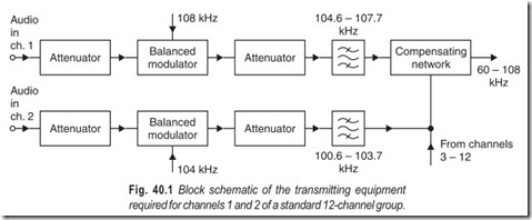
Figure 40.1 is a block schematic of the transmitting equipment required for channels 1 and 2 of a standard 12-channel group. The audio input signal to a channel is applied to a balanced modulator together with the carrier frequency appropriate to that channel. The input attenuator ensures that the carrier voltage is 14 dB higher, than the modulating signal voltage, as required for correct operation of the modulator. The output of the modulator consists of the upper and lower sideband products of the amplitude modulation process together with a number of unwanted components.
Following the modulator is another attenuator whose purpose is two-fold. Firstly, it ensures that the following bandpass filter is fed from a constant-impedance source—necessary condition for optimum filter performance—and secondly, it enables the channel output level to be adjusted to the same value as that of each of the other channels. The filter selects the lower sideband component of the modulator output, suppressing all other components. To obtain the required selectivity, channel filters utilising piezoelectric crystals are employed. The outputs of all the twelve channels are combined and fed to the output terminals of the group. The transmitted bandwidth is 60.6–107.7 kHz, or approximately 66–108 kHz.
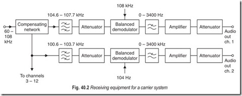
The equipment appropriate to channels 1 and 2 at the receiving end of the 12-channel group is shown in Fig. 40.2. The composite signal received from the line, occupying the band 60–108 kHz, is applied to the twelve paralleled, channel filters. Each filter selects the band of frequencies appropriate to its channel, 104.6–107.7 for channel 1, and passes it to the channel demodulator. The attenuator between the filter and the demodulator ensures that the filter works into a load of constant impedance. The demodulator is supplied with the same carrier frequency as that suppressed in the transmitting equipment. The lower sideband output of the demodulator is the required audio-frequency band of 300–3400 Hz and is selected by the low-pass filter. The audio signal is then amplified and its level adjusted by means of the output attenuator.
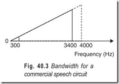
The assembly of the basic 12-channel carrier group can be illustrated by means of a frequency spectrum diagram. The spectrum diagram of a single channel is given in Fig. 40.3. The actual speech bandwidth provided is 300–3400 Hz but a 0–4000 Hz bandwidth must be allocated per channel to allow a 900 Hz spacing between each channel for filter selectively to build up.
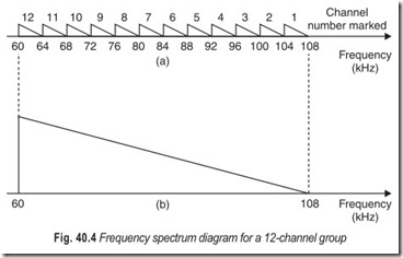
Figure 40.4 (a) shows the frequency spectrum diagram for the 12-channels forming a group; the carrier frequency of each channel is given and so are the maximum and minimum frequencies transmitted. It can be seen that all the channels are inverted; that is,the lowest frequency in each channel corresponds to the highest frequency in its associated audio channel, and vice versa. Since all the channels are inverted, the group may be represented by a single triangle as shown in Fig. 40.4 (b).
The 12-channel system can be used as a building block for the next larger assembly stage or as a system which can be transmitted to line in its own right. Five 12-channel groups can be combined to form a 60-channel supergroup. Five supergroups make up a 300-channel mastergroup. Three mastergroups make up a 3872 kHz bandwidth supermaster group. Alternatively, fifteen supergroups may be assembled direct to form a hyper group, sometimes called a 15 supergroup assembly.
SUBMARINE CABLES
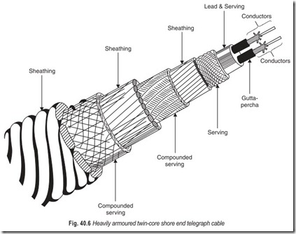
Early submarine cables were all for telegraphy, the distortionless wider band needed for telephony could not economically be transmitted over long lengths of cable until component designers had produced long-life trouble-free units, capable of operating for many years in the depths of the oceans without fault incidence. These units, called repeaters, were designed to amplify incoming signals to offset the transmission losses incurred in the previous section of cable. It was also necessary to provide equalisation to offset the way different frequencies in the wideband information signal had been attenuated by different amounts. Such items were produced in the USA in the 1950s, and repeaters suitable for insertion in deep-sea cables were soon designed in America, Britain, France and Germany.
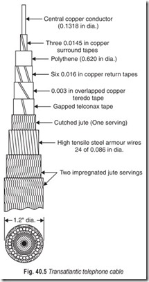
The first major submarine telephone cable was TAT-1. It had a capacity of 50 voice circuits. It is no longer in use. With the advance of technology it has become possible for wider bandwidths, meaning more circuits, to be transmitted. The latest transatlantic cable, TAT-6, has a 30 MHz bandwidth and an installed capacity of 4000–3 kHz circuits.A submarine cable is sometimes under considerable tension, especially when it is being picked up from the sea bed, so great tensile strength is necessary in addition to the ability of the cable and repeaters to withstand the high pressures of deep waters. Early telephone cables were made up in a generally similar way to the 19th century submarine telegraph cables, with one or more layers of heavy steel armour wire to provide the necessary protection (Fig. 40.5).
The cores of the two types of cable were, of course, quite different; telegraph cables usually had a heavy, well insulated copper conductor to carry the signal current, with the return current normally flowing through the sea itself, where as wide-band telephone cables are of coaxial type, i.e. they have a central copper conductor, surrounded by a carefully dimensioned insulant, then copper tapes as a return-path outer conductor, then more insulant, then the outer armour wires.
Cable systems are now used together with satellite radio systems. There is an economic and security need for both types of communication media to be used, most countries feel that it would be unwise to depend completely on any one system and no doubt fibre optics will enable cable manufacturer to provide circuits more economically than is now possible.
EXERCISES
Descriptive Questions
1. Draw the block diagram of the transmitting equipment of a carrier system and explain briefly.
2. Draw the block diagram of the receiving equipment of a carrier system and explain briefly.
3. Sketch the bandwidth for a commercial speech circuit.
4. Draw the frequency spectrum diagram for a 12-channel group.
5. What is the need for submarine cables?
6. Write short notes on :
(a) Supergroup (b) Mastergroup
(c) Super master group (d) Hypergroup
Fill in the Blanks
1. Most of the world’s long distance telephony systems employ ……………………….. groups.
2. A complete group of 12-channels occupies a bandwidth from……………………….. to ……………………….. .
3. The attenuator ensures that the filter works into a load of……………………….. impedance.
4. Repeaters are designed to amplify incoming signals to offset……………………….. .
5. The 12-channel group can be used as a……………………….. for the next larger system.
6. The latest transatlantic cable has a 30 MHz bandwidth and an installed capacity of ……………………….. circuits.
ANSWERS
Fill in the Blanks |
||
|
1. 12-channel 4. transmission losses |
2. 60 kHz, 108 kHz 5. building block |
3. constant 6. 4000–3 kHz. |
