Electrical System
In dealing with the electrical system of the modern automobile, perhaps the most important point to remember is that the Single Wire system is used exclusively. Instead of running two wires from the battery to a lamp, for example, one wire is used to connect the battery to the lamp, and the frame of the vehicle is used in lieu of the other wire to carry the current to or from the battery, depending upon which post of the battery is grounded.
Where the ground is on the positive post of the battery, all operating electrical units are con nected to the negative side of the battery, and current flows from the ungrounded (live) post of the battery through the chassis of the car (the ground) which is connected to the positive bat tery post.
Where the negative post of the battery is grounded, the current flow is in the opposite di rection, through the chassis, then through the elec trical units and back into the battery through the wires connecting them to the battery.
Thus, current flow is always from negative to positive regardless of which terminal is grounded. Confusion occurs in the minds of some people because they associate negative (-) with ground and, in fact, this convention is sometimes used. Nevertheless, in automotive practice the actual battery post that is grounded, whether positive or negative, is designated the “ground”.
While all cars presently being produced have 12 volt systems, the text will frequently refer to 6 volt examples as well. This is done to furnish a con trast between modern 12 volt electrical systems and the older 6 volt systems or to better illustrate basic principles.
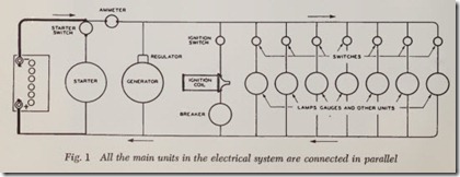
The principle on which the circuit is based is quite simple: All the main units are connected in parallel, Fig. 1, while the switches that control these units are naturally connected in series with the units they control.
The term switches usually mean those devices for closing and opening circuits which are oper ated by hand or foot at the will of the driver or his passengers. Switches that are automatically oper ated include the distributor breaker points, and various starter, generator and horn relays. For simplicity, only hand operated switches are shown in Fig. 1except for the breaker.
WIRING DIAGRAMS
In Fig. 1, two parallel wires are shown and the various units are shown between them. Current flows out from the battery by way of the top wire and back to the battery by way of the lower wire. However, since the car is mostly made of metals, two wires are unnecessary, since the metal of the car itself can be used as the return conductor, Fig. 2, where the broken line is intended to indicate that the return circuit is through the car itself. Sometimes a heavy solid line is used instead of a broken line.
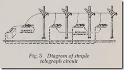
The same scheme is used in telegraph circuits,Fig. 3. The sender’s instrument sends impulses out over a single wire. The impulses operate various receiving units along the way and the return cir cuit to the sender’s instrument is through the ground (earth itself)-hence the name ground. We will call this a grounded return circuit. The earth is a satisfactory conductor for the purpose.
The sending instrument is simply a handy switch connected to a battery or other source of direct current. The receiving instruments are noisy, mag netically-operated relays which give audible “dots” and “dashes.”
Fig. 4 is the same as Fig. 1 except that each ground connection is represented by an inverted triangle made of parallel lines.
Because of the large cross-sectional area of the various metal parts in the car the resistance is small even though iron and steel have a much higher resistance than copper. Therefore, the volt-age drop in this part of the circuit is negligible provided that clean and tight metal connections exist between the various metal parts involved.
For example, provided headlamp units, stop and tail lamp units, etc. are held in place with a single bolt or screw having a clean, tight connec tion with the body, current will :Bow satisfactorily and voltage drop will be negligible. However, if the unit is loose and good metal-to-metal contact is not made, there will be a voltage drop and that particular light will not be as bright as it should be.
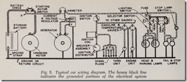
Fig. 5 is a wiring diagram which gives more details than Fig. 1 although the arrangement of units is similar. The ground or return circuit is shown as a heavy_ black line because this method seems clearer than the conventional methods shown in Figs. 2 and 4.
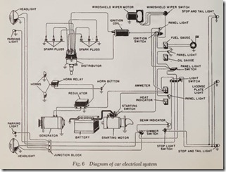
A car wiring diagram which includes all units except extras such as heater and radio is shown in Fig. 6. Because of its complication it is n ecessary to show the ground by triangles of parallel lines as in Fig. 4. All the units are in parallel although they may not seem to be at first glance.
The various units arc usually ground ed by electrically connecting one side of the unit to its hous ing. Then the housing is attached to some metal portion of the car. Therefore, the simple act of installing the unit automatically completes the ground connection.
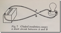
The term “short circuit” means that the circuit has been accidentally shortened. For example, in Fig. 7, if the insulation of the two wires should rotor chafe away at A-B, so that the bare wires touch each other, current would flow from the battery, through point A-B instead of through the lamp and, therefore, the lamp would fail to light.
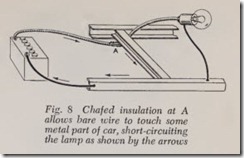
It is not uncommon for the insulation on a wire to be chaf ed away by rubbing on some metal part of the car. As soon as the bared wire touches the metal of the car a short circuit occurs. This type of short circuit is often called a “ground” or we say that the wire is grounded since current flows from wire to ground instead of to the unit to which it is supposed to go, Fig. 8. Chafed insulation at A causes current from the battery to flow through the frame cross member instead of to the lamp, and from thence through the frame back to the battery.
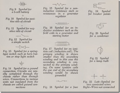
The usual wiring diagram is not always pre sented in the manner shown in Fig. 6. Instead of picturing the units in their realistic form, various symbols are used to indicate them. The most common symbols used are shown in Figs. 9 to 22, inclusive.
At this time it might be well to take the confu sion out of the wiring diagram shown in Fig. 6. There are a great many circuits to follow. But inasmuch as only one circuit usually gives trouble at a time we will break them down into their seven basic circuits, tell what each includes and what each one does. (In the illustrations, ‘each c!rcuit is emphasized by the heavy black por tions.) The seven basic circuits are:
1. The starting circuit.
2. The charging circuit.
3. The ignition circuit.
4. The horn circuit.
5. The electric windshield wiper circuit.
6. The instrument circuit.
7. The lighting circuit.
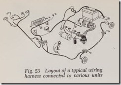
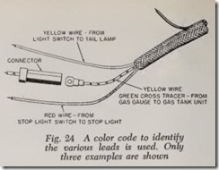
Bear in mind that wiring diagrams are invariably schematic, which means that the position of the wires and units in the diagram are not neces sarily the position they assume on the vehicle. Fig. 23 is an example of a typical wiring harness con nected to various units. Fig. 24 shows a few examples of how a color code is used to identify wires and the units to which they are connected.
At the end of this chapter some car manu facturer wiring diagrams have been included so the reader will be acquainted with the various cir cuits and styles.
The Starting Circuit
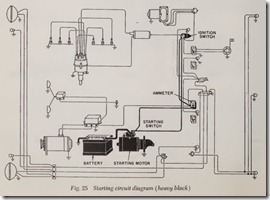
As shown in Fig. 25, this circuit includes the battery, starting switch, ignition switch, starting motor, connecting wires and car frame.
The starting circuit is designed to carry high current with a minimum loss of voltage. The start ing motor cranks the engine for starting while the battery supplies the power and the switch controls the operation.
The starting motor must supply a high cranking power for a short time. And it must engage its pinion with the engine flywheel when cranking, and disengage the pinion as soon as the engine starts.
The Charging Circuit
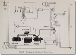
Fig. 26 illustrates the component parts of this circuit. They include the battery, generator, gen erator tell-tale light, regulator, connecting wires and car frame.
The generator, this term is used to include both ordinary generators as well as alternators, supplies all the electricity both for recharging the battery and for use by the other electrical equipment. Notice that the generator tell-tale light is used on this and subsequent diagrams to indicate when the generator is charging. Some cars come equipped with an ammeter instead of a tell-tale light that shows the actual amount of current the generator is providing at any given moment or the amount of circuit discharge if it is not charging.
The regulator controls the output of the gen erator to conform to the requirements of the var ious circuits, prevents high voltage and resultant damage to the generator and electrical system, and keeps the battery fully charged unless the demands have exceeded the capacity of the gen erator.
The Ignition Circuit
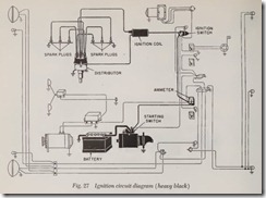
The circuit, Fig. 27, includes the battery, gen erator tell-tale light, ignition switch, coil, distribu tor, spark plugs, connecting wires and car frame.
The purpose of the ignition system is to ignite the fuel in each cylinder at the proper time and to vary the timing to suit the driving or operating conditions.
The ignition coil transforms the low battery voltage into high voltage.
The distributor times the spark and distributes the high voltage to the correct spark plug.
The spark plug is a device for making a spark to ignite the fuel inside the cylinder.
All battery ignition systems have the main components illustrated in Fig. 27. However, the de sign and location of the coil, distributor and spark plugs vary widely for different engines . The con nections to the coil, distributor and spark plugs do not vary greatly, except for the location of the terminals and the order in which the cap towers are connected to the spark plugs.
The Horn Circuit
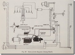
The dual horns illustrated in Fig. 28 have a circuit which includes the batt ery, horns, horn relay, horn button, connecting wires and car frame.
The horns are designed to make a warning sound wh en the horn button is operated.
The relay eliminates the necessity of the button carrying all of the current and reduces burning of the horn contacts.
When only one horn is used, the relay is usually eliminat ed and the horn is not grounded. The cir cuit is simply from the batt ery to horn and to ground and to button.
Often another type relay is used with dual horns. On this type, the relay winding is not con nect ed to the batt ery termin al within the relay but is connected externally at some other point, usu ally the ignition switch. This makes the horns inoperativ e except wh en th e ignition is turned on.
