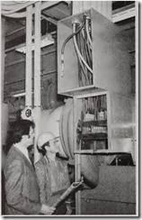
HERMETIC REFRIGERANT motor-compressor, rated 2200 amps at 460 volts, is inspected by John Magliano, electrical design engineer, Syska & Hennessy, Inc., and Vito Caputo, chief electrician, New York Maintenance Co., who provide maintenance services on contract for electrical equipment at the building. Five 400MQM THW Cu cables connect to each of six motor terminals.
Here ‘s a s tep-by-step procedure for applying the NE Code to the design of power circuits supplying 2000-hp, 460-volt cooling equipme nt for a modern skyscraper.
By ROBERT J. LAWRI EAssociate Editor
SELECTI N G and designing equip ment and circu its for cooling the 45-story Celanese Building in Rock efeller Center, New York , presented difficult-to-answer question and complex engineering problems. This is because high-horsepower motors, which normally operate at 4160 volts, had to be powered at 460 volts. As of¬ten happens on projects such as these,
overall design parameters backed by engineering studies showed that a460-volt supply to the cooling equipment would be most desirable.
Consulting engineers Syska & Hen nessy, of N ew York, determined that this 2-million-sq-ft building would re quire 7000 tons of air-conditioning equipment and specified electrically driven machin ery for the job.
The high-capacity circuits and mo tors required to handle this large load provide an interesting case study in complex engineering proble ms. This is because high-horsepower motors, which normally operate at 4160 volts, had to be powered at 460 volts. As of ten happens on projects such as these, overall design paramete rs backe d by engineering studies showed that a 460-volt supply to the cooling equipment would be most desirable.
electrical calculations and design,particularly with respect to NE Code req uiremen ts. While the installation was made in compliance with the City of N ew York Electrical Code, provi sions of this code applicable to the air-cond itioning portion of the job were in agreement with those of the N E Code, with one exception , which will be pointed out. This discussion, therefore, will make reference to re quirements of the more widely used NE Code.
Selecting a voltage
The electrical uti lity brought 13.8 volts into the building and trans formed it to 460-volt utilization volt age. The options for selecting a volt age for the motor compressors were, therefore, few.
Use of 13.8 volts would have meant higher operating costs because of the resu lting dual metering. The costs of 15-kv switchgear, transformers and maintenance were also prohibitive.
Use of 4160 volts, which usually results in greater economy and highest efficiency for such motors, would have meant stepping up from 460 to 4160 volts. At the capacities involved, ini tial costs and high costs of operation and maintenance made this plan also unacceptable.
This left 460 volts. Close study showed the job could be done econom ically and practically at this voltage.
Equipment selected
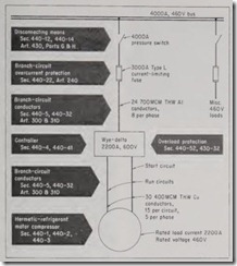
Syska & Hen n essy engineers chose to use four separate air-conditioning units, each powered by a 2200-a m p, 460-volt hermetic motor-compressor, and each supplied by a different ser vice entrance for maximum operating reliability. A typical circu it arrange ment is shown in Fig. 1.
At each of the four service en trances feeding the air-conditioning load, a 4000-amp bus supplies two 4000-amp fused pressure switches. One supplies building power and lighting loads, the other a motor-com pressor.
From the motor-ci rcuit disconnect switch, 24 700MCM, TRW AI conduc tors, 8 per phase are installed in eight 31h-in. aluminum conduit and carry 460-volt power to a wye-delta motor controller. From the controller, 30 500MCM Cu conductors in aluminum conduit carry 460-volt power to the motor.
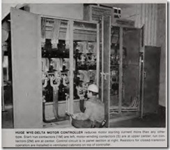
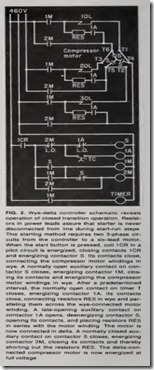
A wye-delta controller was selected because this type of starter reduces starting current and starting torque to 33% of normal-more than any other type. This was important to as sure minimum disturbance to the dis tribution system during starting of the huge motors . ·Circuitry requires two sets of leads to the motor-one for use during starting and both for use during normal running. The con troller automatically connects the mo tor windings in wye as the motor is started; after acceleration, the motor is reconnected for normal delta oper ation. Details of controller operation are explained in Fig. 2.
Applicabl e code rules
The NE Code in Article 440, “Air Cond i tioning and R efrigerating Equipment,” provides guid elines for determining sizes and ratings of con trollers, disconnects, switches, over current protect ive devices, and circuit conductors. Section 440-2(a) states that these provi sions are “in addition to, or amendatory of , the provisions of Article 430 and other Articles in this Code, which apply except as mod ified in this Art icle.” Except for Ar ticle 430, none of the other articles de scribed (garages, hazardous locations, etc.) apply to the Celanese jo b. In ad dition, Articles 422 and 424 are ex cluded by Section 440-2( b), which states that those articles apply only to refrigeration equipment which does not inclu de a hermetic refrig erant motor-compressor.
Because the equipment installed consists only of hermetic ref rigeran t motor-compressors, Articl e 440 was followed on this proj ect plus any ap plicable sections of Article 430 not amended by Article 440.
Marking of equipment
A hermetic refrigerant motor-com pressor is defined by Section 440-1as:
A combination consisting of a com pressor and motor, both of which are enclosed in the same housing, with no external shaft or shaft seals, the motor operating in the refrigerant.
Such equipment is required by Sec tion 440-3 to be marked by the manu facturer with certa in values und er certain conditions in addition to the manufacturer’s name, t ra d emark , phases, voltage, freque n cy, and locked-rotor current. The “rated load current” must appear on all hermeti c refrigerant motor-compress ors. It is defined in this section as follows:
RATED LOAD CURRENT for a hermetic ref rigerant motor-compressor is the current resulting when the motor compressor is operated at the rated load, rated voltage, and rated fre quency of the equipment it serves.
In addition, if the hermetic motor compressor incorporates a protection system that permits continuous cur rent in excess of the specified per centage of nameplate rated load cur rent given in Section 440-52(b)(2) or (b)(4), the equipment must be marked with the “branch circuit selection cur rent.” This is defined in Section 440-3 as follows:
BRANCH-CIRCUIT SELECTION
CURRENT is the value in amperes to be used instead of the rated load cur rent in determining the ratings of mo tor branch-circuit conductors, discon necting means, controllers, and branch circuit short-circuit and ground-fault protective devices wherever the run ning overload protective dev1ce permits a sustained current greater than the specified percentage of the rated load current. The value of branch-circuit se lection current will always be greater than the marked rated load current.
The four hermetic motor-compres sors supplied on this project were marked with a rated load current of 2200 amps and a locked-rotor current of 9750 amps. They do not have inher ent or special protective systems, nor are they marked with a branch-circuit selection current. The 2200-amp value of rated load current, therefore, was used to size circuit components.
Sizing the controller
The size of the wye-delta controller to be used was determined using Sec tion 440-41, which requires the con troller to have continuous-duty and locked-rotor ratings not less than the mot or-compressor nameplate full load current and locked-rotor ratings. Thus, a 2200-amp, 600-volt controller was ordered , with specs calling for a 9750-amp locked-rotor capability.
Branch-circuit design
The ampacity, type and installation details of the branch-circuit conduc tors were work ed out next. The am pacity was determined on the basis of 2200 amps, the rated load current of the motor-compressor, in accordance with Section 440-5(a).
Conductors between the motor controller and the motor were considered
FIG. 2. Wye-delta controller schematic reveals operation of closed transition operation . Resist ors in power leads assure that starter is never disconnected from line during start-run steps. This starting method requires two 3-phase cir cuits from the controller to a six-lead motor. When the start button is pressed, coil 1CR in a pilot circuit is energized, closing contacts 1CR and energizing contactor S. Its contacts close, connecting the compressor motor windings in wye. A normally open auxiliary contact on con tactqr S closes, energizing contactor 1M, clos ing its contacts and energizing the compressor motor windings in wye. After a predetermined interval, the normally open contact on timer T closes, energizing contactor 1A. Its contacts close, connecting resistors RES in wye and par alleling them across the wye-connected motor winding. A late-opening auxiliary contact on contactor 1A opens, deenergizing contactor S, opening its contacts, and placing resistors RES in series with the motor winding. The motor is now connected in delta. A normally closed aux iliary contact on contactor S closes, energizing contactor 2M, closing its contacts and thereby shorting out the resistors RES. The delta-con nected compressor motor is now energized at full voltage.
first. Because the con troller is a wye delta type starter, two main circuits are required-one serves as a starting circuit, and both are used during nor mal running of the motor (see Figs. 1 and 3).
![]() The ampacity of these branch-cir cuit conductors is determined by Sec tion 440-32, which requires branch circuit conductors supplying a single motor-compressor to have an ampac ity not less than 125% of either the motor-compressor rated load current or the branch-circuit selection cur rent, whichever is greater.
The ampacity of these branch-cir cuit conductors is determined by Sec tion 440-32, which requires branch circuit conductors supplying a single motor-compressor to have an ampac ity not less than 125% of either the motor-compressor rated load current or the branch-circuit selection cur rent, whichever is greater.
This means that these conductors must have an ampacity of at least
1.25 x the rated load current, which is 1.25 X 2200 or 2750 amps.
However, in this instance, there are two parallel circuits feeding the mo tor, and when the motor is in normal running mode, the circuits are con nected in delta. Because there are two circuits, the required ampacity must be divided between them. But be cause of the phase-current relation ship in delta circuits, the division will not be arithmetic. Fig. 3 illustrat es this principle.
The ampacity of each circuit can be calculated by multiplying the rated load current by the constant that ap plies to current relationships in bal anced delta systems and by 125%, as required by Section 440-32:
Rated load current x K x 125% = Line current of each circuit.
2200 amps X 0.58 x 1.25 = 1595 amps.
Thu s, a conductor mak eup and ar rangement had to be designed for the two circuits between the controller and the motor, each with a capacity of at least 1595 amps. Since this run was relatively short and since the connec tion at the motor required six termi nals (to provide for the interchange of wye and delta internal mot or winding connections), they decided to use cable in conduit. THW copper conductors were selected because they offered maximum reliability of terminations, which wer e subject to motor vibration. Furthermor e, the ex tra flexibility of copper helped simpl ify connections at the motor termi nals.
Because both the controll er and motor required six terminals , the con ductor mak eup had to be a multipl e of six to permit an equal number of con ductors to be connected to each termi nal. After a review of NE Code Table 310-16, which gives ampaciti es of in sulated copper conductors, th ey found that 400MCM THW conductors would provide th e required ampaci ty and combination of conductors . Ampacity 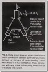
for each phase of each circuit was determined as follows:
Ampacity of on e 400MCM Cu THW conductor = 335 amps.
5 X 335 amps = 1675 amps.
This results in a conductor makeup of five 400MCM copper conductors per phase in each circuit, 15 conductors per circuit, or a total of 30 conductors. The condu ctors are carried in ten 3-in. aluminum conduits, three per conduit. The ampacity of the circuit is the low est possible with the required circuit arrangement.
The requir ed ampacity of the remainder of the branch-circuit conduc tors-those between the controller and the branch-circuit protective de vice, also was 2750 amps, as calculated earlier using Sections 440-5(a) and 440-32. THW aluminum conductors were chosen here because of their lower initial and installation costs. Various cable in conduit makeups were considered to obtain the most economical arrangem ent. The make up selected consists of 24 700MCM THW aluminum conducto rs carried in eight 3’h-in. aluminum conduits, 3 per conduit.
Overload protection
Section 440-52 lists four different methods that may be used to protect the motor-compressor, the control ap paratus and the branch-circuit con ductors from operating overcurrent. Maximum settings of each overload protective device or system are also given as a specified percentage of nameplate rated load current or branch-circuit selection current.
The four overload protective meth ods and their maximum rated set tings are: (1) separate overload re lay-140 % of rated-load current; (2) thermal protector integral with mo tor-compressor-156% of rated-load current (or branch-circuit selection current); (3) fuse or inverse-time cir cuit breaker-125% of rated-load cur rent; (4) protective system furnished, specified or approved for use with the motor-compressor-156% of rated load current (or branch-circuit selection current). Article 440-21 also requires that provisions of Article 240, “Over current Protection,” be applied.
On this installation, overload pro tection is provided by separate over load relays installed in the wye-delta controller. Trip settings were deter mined in coordination with the equip ment suppliers because of the unusual arrangement of conductors between the controller and motor. Note in Fig. 2 that when the motor is in the nor mal running connection, all six con ductors between the motor and con troller carry running current (2200 amps), but that overload relays are installed in only three of these con ductors. Actually, strict adherence to Section 440-52(a)(1) would result in the motor-compressor being improp erly protected, since the last para graph in Section 430-32 states:
Where a separate motor-running overload device is so connected that it does not carry the total current desig nated on the motor nameplate, such as for wye-delta starting, the proper per centage of nameplate current applying to the selection or setting of the over load device shall be clearly designated on the equipment, or the manufac turer’s selection table shall take this into account.
Therefore, the setting of the over load relays was based on the current flowing in one of the two circuits to the motor. Because of the delta circuit arrangement, the proper percentage of nameplate current required can be determined by multiplying the con stant 0.58 by the rated-load current (2200 amps) to obtain a phase current of 1276 amps. The overload relays were then set at less than 140% of 1276 amps in accordance with Section 440-52(a)(1).
Branch-circuit protection
The required fuse rating or circuit breaker setting of the motor branch circuit overcurrent protective device is covered in Section 440-22. This sec tion states that the short-circuit (and ground-fault protective device) shall be capable of carrying the starting current of the motor and shall have a rating or setting not exceeding 175% of the rated load current (or branch circuit selection current, whichever is greater).
In the event that the protective de vice cannot carry the starting current of the motor, its rating or setting may be increased, but the rating or setting cannot be higher than 225% of the rated-load current (or branch-cir cuit selection current, whichever is greater). Thus, the maximum rating or setting of the branch-circuit over current device was determined to be 2200 amps X 1.75, or 3850 amps.
Because of the high short-circuit current available, they selected a fu sible switch to serve as the branch circuit disconnect and overcurrent de vice. This was done primarily because the fusible switch was less costly than a power circuit breaker backed by the current-limiting fuses that would have been required.
Next, they consulted fuse manufacturers’ data and, based on motor de sign criteria, selected a Class L, time delay, current-limiting fuse rated 3000 amps, 200,000 amps IC. The 3000- amp fuses, which according to fuse data will carry the motor starting current without nuisance tripping, will provide better protection than a fuse rated at the maximum value per mitted.
Motor disconnecting means
Section 440-12 states that the dis connecting means serving a hermetic refrigerant motor-compressor must have an ampere rating of at least 115% of the nameplate rated load cur rent or branch-circuit selection cur rent, whichever is greater. Section 440-14 requires that the disconnect ing means be located within sight from and readily accessible from the equipment. A small-print note points out that Parts G and H of Article 430 contain additional requirements that must be met.
Section 430-109 in Part H of Article 430 states that the motor disconnect ing m ean s shall be a motor-circuit switch rated in horsepower or a circuit breaker. Article 100 defines a motor-circuit switch as:
A switch, rated in horsepower, ca pable of interrupting the maximum op erating overload current of a motor of the same horsepower rating as the switch at rated voltage.
Exception No. 4 of Section 430-109 permits the use of a motor-circuit switch rated in amperes for motors rated over 100 hp.
Because fuses had been chosen for the motor branch-circuit short-circuit protection, the first step in selecting the motor disconnecting means was sizing a fusible switch in compliance with the above code rules:
2200 amps X 1.15 = 2530 amps.
Thus, a 3000-amp switch, furnished with the 3000-amp fuses previously selected, would be suitable.
However, the engineers specified a 4000-amp switch. This was done be cause the above calculations were made while the motor was being built, and all calculations had to be made on the basis of the manufac turer’s motor design data. Using pru dent forethought they realized that it was possible, in the event of a design change or unforeseen field conditions, that the actual motor starting or run ning current, or both, could be higher than the design value submitted. Knowing that the fuse size selected was as low as possible to provide max imum protection (a 3000-amp fuse was chosen based on a maximum per missible value of 3850 amps), they knew it was possible that the 3000- amp fuses might not be able to handle the motor currents drawn during actual operation.
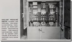
If a 3000-amp switch was installed, it would be impossible to provide fuses of a larger size. Therefore, a 4000-amp switch was specified so that higher rated fuses could be used if necessary. To meet interrupting ca pacity requirements, they called for a pressure-type switch (see photo).
Disconnect location. Location of system equipment was vital to safe, eco nomical installation. To keep conduc tor runs as short as possible and to minimize copper losses and voltage drop, all equipment was installed close together and as close as possible to a service entrance. The motor-com pressors and controllers were located in an equipment room on a lower level of the building. The motor discon nectiog means was installed on the floor above the equipment room. This actually is a violation of Sections 440- 14 and 430-102 of the 1975 NE Code, because the disconnect is not within sight and readily accessible from the equipment. However, this arrange ment was approved by local code-en forcing authorities because it com plied with New York City code rules in effect at the time, which permitted out-of-sight location of the motor dis connecting means if it was capable of being locked in the open position. (This was once permitted also by the NE Code.) If the current NE Code rules had been followed, an additional switch at each controller location would have been required, and this would have added considerable cost.
Arc Electrical Construction Co.Inc., New York, was the electrical contractor.
