Calculating torque and heat build-up during motor starting
The efficiency of a motor is higher when it operates as close as possible to its full-load rating. However, the T-frarrw motors now in use have less heat-sink‘ capacity than their predecessors. Knowing torque and heat build-up values during starting will permit motor and load to be matched more closely to the load requirements.
By WILLIAM C. BRODERICK
Chief Electrical Engineer Meyer, Strong and Jones New York, N.Y.
TFRAME motors are smaller physi cally than earlier motors of the same horsepower. Less steel is used in the T-frame construction, encouraged by the use of grain-oriented steels in which the molecules tend to point in one direction and not randomly as in ordinary steel. In a very real way, this steel is more efficient.
In addition to more efficient steel, better grades of insulation have been developed. This permits these new motors to operate normally at higher temperatures. These factors, plus the corresponding reduction in copper or aluminum used in the windings, com bine to make the T-frame motors smaller. The potential for overheating has increased as a result. There simply is less latitude between operating temperature and maximum permissi ble motor temperatures.
The hotter a motor runs, and the longer it runs at elevated tempera tures, the faster will be its ultimate failure, since insulation is a chemical compound and as such it is time temperature related. Starting torque and heat generated during starting can be readily calculated; the information gained can then be used to match motor size to load requirements to obtain the maximum energy efficiency for the system.
Information needed to calculate starting torque and heat generated must be obtained from the manufac turers of the motor and driven equip ment . This includes the permitted locked-rotor time, speed-torque-cur rent curves of the motor and the load, and the moment of inertia of the load.
Calculations required
The motor must produce enough torque to accelerate its rotor and the load. Whether or not it is capable of doing this can be determined by comparing the speed-torque curve of the motor with the speed-torque char acteristic of the load, taking into account the moment of inertia of the rotor and the load. Sometimes a simple comparison of the curves will confirm suitability. For larger motors, calcula tions are usually necessary. The techni que to be described here is known as the “graphical integration” method.
EXAMPLE
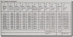
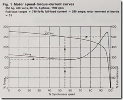
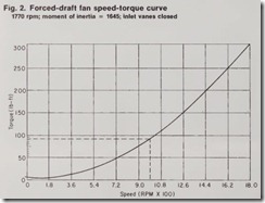
Figs. 1 and 2, together with data supplied by the manufacturers of the motor and the driven load, will be used to calculate the values shown in Fig. 3.
The curves shown in Fig. 1 are typical for a 250-hp, Design B motor. Fig. 2 isa typical curve for a fan with high inertia characteristics. Assume that the vendors supplied the following data: maximum time permitted to drop from locked-rotor current to operating current, 10 sec; rotor moment of inertia, 31 lb-ft2; load moment of inertia,1645 lb-ft2.
The values shown in columns 2 through 11 of Fig. 3 were calculated as follows.
Column 2. Enter the horizontal scale
of Fig. 1 at the center of the speed range as shown by the dashed line.
Proceed vertically to the intersection with the current curve and move right,reading the % full-load amperes on the right-hand vertical scale.
The dashed lines of Fig. 1 show that the motor will be drawing 500% of full-load amperes at 50 to 60% of synchronous speed.
Column 3. Multiply % full-load amps by full-load amps. For the 50 to 60% speed interval,5.0 x 285 = 1425 amps.
Column b- Again, enter the horizontal scale of Fig. 1 at the middle of the speed interval. Proceed upward to the intersection with the torque curve,move left, and read the % torque on the left-hand vertical scale.
Column 5. The voltage drop at the motor, because of line drop and regulation of the source, is maximum at starting and drops as it accelerates to rated speed. For the motor in question,assume a drop of 20 volts—from 460 to 440 volts—at the instant of starting.
This means the voltage at the motor at this instant is 460/440 or 95.7% of rated voltage. For simplicity, the motor voltage during each speed interval is taken as the ratio of the % full-load amps to the % locked-rotor amps multiplied by the initial voltage drop.
For the 50 to 60% range, the voltage drop would be 500/560 x 20, or 17.9 volts. (The % locked-rotor amps is obtained from the current curve of Fig.
1 at 0% speed.) The motor voltage at this speed range is thus 460 – 17.9, or 442.1 volts, which is 442.1/460 or 96.1% of rated voltage.
Column 6. Torque varies approximately as the square of the voltage.
Therefore, the % torque values are obtained for each speed range by multiplying the value in column 4 by the square of the value in column 5.
For the 50 to 60% range, 1.41 X 0.9612 = 1.302, or 130.2%.
Column 7. In Fig. 2, the fan manu 
factur er’s speed-torque cu rve has been di vided into 10 speed ranges of 180 rpm each to m atch the 10 ranges of the m otor curves. En ter Fig. 2 at the middl e of the speed range and proceed vertically to th e cur ve, read i ng the torqu e on the l eft-hand scal e at the i nt ersection with the curve. For the 50 to 60 % m otor speed range (which is 990 rpm f an speed), the torque is 92.5 Ib-ft. This valu e is th en con verted into % motor full-l oad torque. (Later, the fi nal resu l ts will be converted from % to lb-ft.) Sin ce the motor full-load tor qu e is 740 l b-ft (Fig. 1), 92.5/740 = .125 or 12.5%.
Column 8. Net torque is the torque developed by the motor m i nus the torque required for the load: column 6 m inu s colum n 7. For the 50 to 60% range, th i s is 1:i0.2% – 12.5%, or 117.7%.
Column .9. To con vert the % net tor que to lb-ft, column 8 is multiplied by 740, the moto r full-load torque: 1.177 X 740 = 871 l b-ft.
Column 10. The time taken for each speed interval is given by sm/308T ,
where
s = speed increment
m = moment of inertia (load + rotor).
T = torque (from column 9).
In thi s exampl e, the speed increment is 180 rpm; the total moment of inertia is 164 5 + 31, or 1676. Th e value 308 is a constant. Thus, the time spent in the 50 to 60% speed range is (180 X 1676)
+ (308 X 871.0), which is 1.12 sec.
The increments of time for each speed range in column 10 are then added to find the total time required to accelerate the load to rated speed, in this case 9.78 seconds. Since the motor manufacturer specified a 10-sec maxi mum time for the motor current to drop to its full-load value, the 9.78-sec value indicates that the motor is suit able for the load from this standpoint. Column 11. Heat losses in any elec trical system are FR losses; that is, they are determined by resistance and the square of the current. Since both motor rotors and stators have resist ance at locked-rotor, heat can be expected to develop. When the mass of the housing, rotor, and conductors are considered in terms of a thermal heat sink, overtemperature would not seem to be a problem. At starting, however, there is no time to transfer and store heat and reach thermal equilibrium.
Thermal limits can be reached in seconds.
The time required to accelerate the load (9.78 sec) in this example is very close to the 10-sec maximum allowed. This could be of concern, especially at initial starting, when the lubrication may he stiff. Most manufacturers will list two values-one for cold starts, one for hot starts.
A relatively simple approximation of J2t may he made to check that the
thermal limitations of the motor will not be exceeded during the staring period. The maximum Ft will be devel oped with locked-rotor current flowing at the initial instant of starting. From Fig. 1, locked-rotor current is 560(Jr, of 285, the full-load amperes, which is 1596 amps. For the 9 sec allowed, the maximum J2t allowed would be (159’3)2 X 9, or 22,924,944 amp2-sec.
Calculating the J2t for each of the speed ranges of Fig. 3 and totaling them will give the total Pt during the 9.78-sec starting period in this exam ple. This has been done in column 11. For the 50 to 60 % speed range, 1125 amps2 (column 3) X 1.12 sec (column10) = 2,274,300 amp2-sec. The sum ofall values in column 11 is 20,154,742 amp2-sec, which is less than the maxi mum permitted value of 22,924,94’1. It should be noted that this is a conserva tive figure, since the hot starting time will normally he shorter than the <·old starting time calculated and no allow ances have been made for heat transfer.
Thus, the motor is suitable for the load and closely matched to the load requirements both from a standpoint of accelerating time and Ft.
For practical, everyday purposes,especially for such low-inertia loads as supply and exhaust fans, a single-step calculation usually is sufficient. Thus, in this example, a single 1800-rpm stPp could be considered instead of ten 1SO rpm steps.


