Some Digital Audio Processes Outlined
While digital audio is a large subject, it is not necessarily a difficult one. Every process can be broken down into smaller steps, each of which is relatively easy to follow. The main difficulty with study is to appreciate where the small steps fit into the overall picture. Subsequent chapters of this book will describe the key processes found in digital technology in some detail, whereas this chapter illustrates why these processes are necessary and shows how they are combined in various ways in real equipment. Once the general structure of digital devices is appreciated, other chapters can be put in perspective.
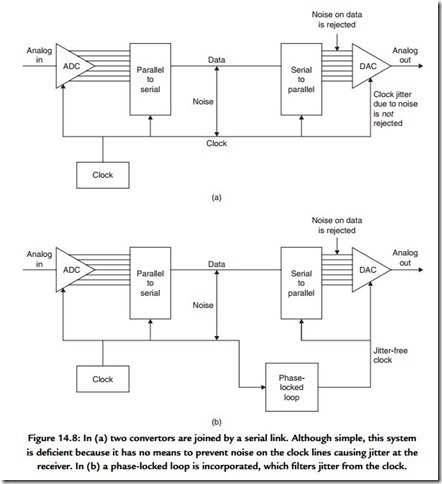
Figure 14.8(a) shows a minimal digital audio system. This is no more than a point-to-point link that conveys analog audio from one place to another. It consists of a pair of convertors and hardware to serialize and deserialize the samples. There is a need for standardization in serial transmission so that various devices can be connected together.
Analog audio entering the system is converted in the ADC to samples that are expressed as binary numbers. A typical sample would have a wordlength of 16 bits. The sample is connected in parallel into an output register that controls the cable drivers. The cable also carries the sampling rate clock. Data are sent to the other end of the line where a slicer rejects noise picked up on each signal. Sliced data are then loaded into a receiving register by the clock and sent to the digital-to-analog convertor (DAC), which converts the sample back to an analog voltage.
As Figure 14.4 showed, noise can change the timing of a sliced signal. While this system rejects noise that threatens to change the numerical value of the samples, it is powerless to prevent noise from causing jitter in the receipt of the sample clock. Noise on the clock means that samples are not converted with a regular time base and the impairment caused will be audible.
The jitter problem is overcome in Figure 14.8(b) by the inclusion of a phase-locked loop, which is an oscillator that synchronizes itself to the average frequency of the clock but which filters out the instantaneous jitter.
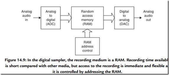
The system of Figure 14.8 is extended in Figure 14.9 by the addition of some RAM. What the device does is determined by the way in which the RAM address is controlled.
If the RAM address increases by one every time a sample from the ADC is stored in the RAM, an audio recording can be made for a short period until the RAM is full. The recording can be played back by repeating the address sequence at the same clock rate but reading the memory into the DAC. The result is generally called a sampler. If the memory capacity is increased, the device can be used for general recording. RAM recorders are replacing dictating machines and the tape recorders used by journalists. In general they will be restricted to a fairly short playing time because of the high cost of memory in comparison with other storage media.
Using compression, the playing time of a RAM-based recorder can be extended. For unchanging sounds such as test signals and station IDs, read only memory can be used instead as it is nonvolatile.

