Electrical circuits
Electrical circuits are circuits used to interconnect different electrical equipments together to enable the working of an electrical device.
Electrical schematics are commonly classified into power circuit and control circuit. A power circuit consists of the main power device (a motor, a generator, or other power devices) along with heavy power conductors, contactors, protection devices.
A control circuit consists of switches, field device contacts, timers, relay coils, relay contacts, protection devices, and light power conductors.
Power circuits
Power circuits are required for carrying power to or from heavy electrical equipments like motors, alternators, or any electrical installation.
They carry out the following functions:
• Isolation using devices such as isolators, linked switches and circuit breaks.
• Circuit control using devices such as contactors, motor circuit breakers, etc.
• Protection against overload and short-circuits using thermal overload relays, electro-magnetic relays, circuit breakers, with releases, fuses, etc.
Power circuits have to carry heavy power and therefore, they consist of heavy conductors along with contactors used for switching the power on and off. Protection devices are also included in the same power circuit for resolving an overload condition or any other concerned faults.
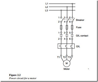
For example, Figure 2.2 depicts a Direct-on-line (DOL) starter power circuit used for a three-phase induction motor. As shown, the three-phase power input is connected to the
motor through a contactor. Power is passed to the motor when the contacts (of the
contactor) are in closed condition. Protection devices such as fuses, and overload relays are provided in series with power conductors to detect unhealthy conditions during operation.
A control circuit is for the automatic control of equipment, for safety interlocking, and sequencing the operations of the plant equipment and machines.
Control circuits hardware consists of relay contacts, wires, hardware timers, and counters, relay coils, etc. These consist of input contacts representing various conditions;
the output coils are energized or de-energized depending on the input conditions represented by the control circuit.
Input contacts represent the binary state of the condition:
• True or false
• On or off.
There are two types of contacts NO (normally open) and NC (normally closed).
• Input contact: These are contacts of relays, contactors, timers, counter, field instrument switches, pressure switches, limit switches, etc.
• Output coil: These have two states – On or Off. Output coil can be auxiliary contactor or Main contactor coil.
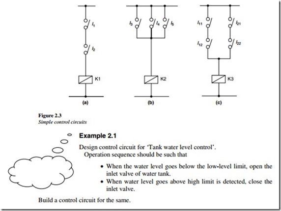
A few simple control circuits are shown in Figure 2.3 to represent logical AND, OR, and such conditions.
1. ‘AND’ operation circuit
Figure 2.3(a) shows a simple control circuit (AND operation) with two input contacts (NO) representing two conditions that must be true to complete the circuit to switch on the output relay coil and change the state of output from ‘Off’ to ‘On’.
2. ‘OR’ operation circuit
Figure 2.3(b) shows a circuit with three input contacts (NO) representing that at least one of the three conditions should be true to complete the circuit to switch On the relay coil and change output state from ‘Off’ to ‘On’.
3. ‘AND with OR’ operation circuit
Figure 2.3(c) shows a control circuit, consisting of a combination of AND and OR operations.
There are two parallel (OR condition) paths with two input contacts (NO) connected in series in each path representing AND conditions. The path for coil K3 will be completed when one of the path conditions comes true. The circuit then will switch ‘On’ the relay coil and change the output state from ‘Off’ to ‘On’.
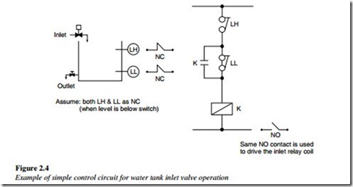
As shown in Figure 2.4, when the level is initially low, coil K will pickup (since both level switch NC contacts will remain as it is), thus energizing the inlet valve to open.
As the level rises above switch LL, its NC contact will open but still coil K will remain latched through latching contact K.
Once the level rises above switch LH, its NC contact will open causing coil K to de-latch or de-energize and the inlet valve will close.
Now, coil K will not pickup or inlet valve will not open unless the water level drops below low-level switch LL.


