De Armature Rewinding Procedure
The process of insulating an armature core, preparatory to rewinding, is one of the most important steps in the rewinding procedure. The selection of proper insulating materials, the method of application of this material, and the proper alignment of core laminations insure the armature against premature insulation troubles. The procedures outlined below aid in covering all the important points of preparation, selection, and application of the insulations.
CLEANING SLOTS AND TRUING UP LAMINATIONS
After the old winding has been removed, the core slots, core ends, and the shaft must be thoroughly cleaned of all old insulation and varnish.
1. Inspect the core for rough or irregular spots, sharp edges and burrs, and bent, broken, or burred lamination teeth.
2. Remove clinging particles of old insulation and varnish by scrap ing. A solution of 25 percent alcohol and 75 percent benzol will aid in removing stubborn particles. Do not apply any solution to the commutator. Use a cloth moistened, but not wet, with solution for cleaning the commutator.
3. Use a hammer and drift for straightening bent slot teeth and laminations.
4. Use an arbor press to force laminations together which may have flared or separated.
5. Use a file to smooth sharp edges and burrs.
6. Use a file to clear and true-up wedge grooves and band grooves.
Use only enough pressure on the file to clear and true the grooves to their original dimensions. Removal of more metal than is necessary will cause wedges and bands to come loose after installation.
7. Use compressed air to blow out loose particles of metal, insula tion, and varnish.
INSULATING THE CORE ENDS AND SHAFT
The insulation for the core ends are fiber washers about 1/16 inch ( 1.6mm) thick, punched to conform to the core-lamination slots, and having a tight-fitting hole for the shaft. This serves as a protection for the windings that cross the ends of the core. When reinsulating a core and shaft, proceed as directed below:
1. Cut out two discs of 1/16-inch (1.6mm) fiber to the diameter of the core to be reinsulated.
2. Punch out a tight-fitting hole for the shaft on both sides.
3. Punch out slots to conform to the width and shape of the core slots on both disks.
4. Shellac both ends of the core.
5. Shellac one side of each fiber disc.
6. Assemble and align both end washers to the core.
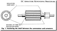
7. Wrap, half-lap, and shellac about four layers of 3/4-inch-wide (20mm) treated cloth tape (black or yellow cambric) on the armature shaft. Start close to the rear-end washer at a point where the end windings will extend. Use masking tape to hold the wrapping down and to facilitate rewinding, Fig. 1.
8. Repeat step 7. Start up close to the front -end washer and wrap up close to the back of the commutator. Fig. 1.
REPLACING THE COMMUTATOR
The commutator of a large armature merely requires bolting the commutator properly into place. However, the commutator of a small armature necessitates the use of an arbor press and proper-fitting arbor sleeve for the shaft and commutator. In the absence of an arbor press, a correctly sized arbor sleeve and hammer may be used. The procedure outlined below gives steps to follow when replacing a commutator:
1. Prepare a piece of pipe of sufficient length and diameter for use as an arbor sleeve. Do not use a pipe of an outside diameter which will bear on the commutator bars. The pipe should bear only on the cast iron hub of the commutator; otherwise irreparable dam age may result to the commutator.
2. Determine the length for the pipe by measuring the distance along the front end of the shaft, from the front end of the armature core to the front end of the shaft. Then subtract from this measurement the commutator length and the recorded distance between the back of the commutator and the front end of the armature core. The result will be the proper length for the pipe.
3. Align the commutator with the shaft, key, and keyway of the commutator hub.
4. Slip the arbor sleeve (pipe) over the shaft, and align it with the hub of the commutator.
5. Tap the end of the pipe with a hammer to get the commutator started on the shaft shoulder.
6. Set the back end of the armature shaft on a block of soft iron, bronze, or brass of 1/4- to 1/2-inch (6mm to 12mm) thickness in an arbor press.
7. Center the ram of the arbor press on the pipe which is centered on the hub of the commutator or located on the front end of the armature shaft.
8. Apply gradual pressure until the commutator is driven into proper position. Be certain that the commutator is driven evenly on the shaft by constantly watching as pressure is applied.
After the commutator is replaced on the shaft, fill the hollow area between the core and the back of the commutator. Filling this space before or after winding, or filling part of it before, and part of it after winding, will depend on the armature size. The procedure given below will aid in either case.
1. When the bottom of the core slots are lower than the bottom of the commutator riser slots-
a. Use wide tape of cambric or cotton, or if wide tape is not available, cut wide strips of cambric.
b. Wrap and fill the space up to the bottom level of the core slots.
c. Secure the wrapping with a layer of masking tape and insulate and rewind the armature.
d. After rewinding the armature, fill the space between the end windings and the bottom level of the commutator-riser slots with cambric or cotton tape. Secure the wrapping with a layer of masking tape.
2. When the bottom of the core slots are on a level with, or fairly close to the bottom level of the commutator-riser slots-
a. Use cambric or cotton tape.
b. Wrap and fill the space up to the bottom level of the commu tator-riser slots.
c. Secure the wrapping with a layer of masking tape, and insulate and rewind the armature,
INSULATING THE SLOTS
A good commercial grade of slot-insulation paper should be used. This paper is supplied in sheets, strips, or cuffed strips in various thicknesses. For 120-volt armatures with slots not over 3/8 inch (10mm) in width and wire for the coils not larger than No. 28 AWG gauge, 1.8 to 0.010 inch is the thickness of paper to use. For 240-volt armatures, use insulation no less than 0.010 inch thick with coil wire no greater than No. 28 AWG gauge. The insulation thickness will depend upon the available room in the slot. For slots larger than 3/8 inch ( 1Omm) in width and coil wire which is as large or larger than No. 18 AWG gauge, use slot insulation no less than 0.916 inch (about 23.25mm) thick. If room is available in the slot, use thicker insulation and, if it is possible, use insulation of 0.023 inch thickness. Do not use insulation paper of two thicknesses to make up a required thickness. Thin insulations are weaker and tear more easily, especially in large slots.
1. Continuous-strip method of insulating slots follows, Fig. 2.
a. Cut a strip of insulation 1/8-inch (3mm) wider than the length of the slot, including the thickness of the fiber end washers if they are encompassing the slots. Cut it long enough to pass entirely around the core and loop into every slot.
b. Push one end of the insulation into the first slot, with a stiff fiber drift plate, leaving about 1/2-inch (12mm) of the end of insulation protruding from the slot. Continue to shape and fit the insulation into the slot with the fiber drift plate.
c. Insert a dowel into the first slot if the slot is circular, or insert a piece of fiber shaped to the slot if the slot is angular.
d. Insert the strip insulation into the next slot. Shape and fit the insulation to the slot with the fiber drift plate.
e. Insert a second dowel or preshaped fiber into this slot.
f. Insert the strip insulation into the next slot. Shape and fit the insulation to the slot with the fiber drift plate.
g. Remove the dowel or shaped fiber from the first slot and insert it into the third slot.
h. Continue this operation for all the slots.
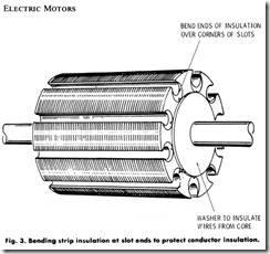
i. Bend the insulation at the end slots, Fig. 3.
j. Rewind acccording to winding procedure.
1. Cut-insulation method for small slots.
a. Cut a strip of insulation to fit the inside periphery of the core slot, plus an allowance of 1/2-inch (12mm).
b. Center and crease the insulation strip length on the insulation
former or blunt scriber according to the inside dimensions of the bottom of the core slot.
c. Cut the insulation strip length into sections which are 1/2-inch ( 12mm) longer than the length of the slot.
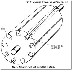
d. Insert the insulation sections into the slots with 1/8-inch (3mm) protruding at each end. Fig. 4.
e. Fold back the 1I4-inch (6mm) protruding ends of insulation along the length of the slots to reveal the opening and to facilitate threading the winding into the slot.
f. Rewind according to winding procedure.
2. Cut-insulation method for large slots.
a. Cut a strip of insulation which is dimensioned to fit the inside periphery of the core slot.
a. Center and crease the insulation strip length on the insulation former according to the inside dimensions of the bottom of the core slot.
c. Cut the insulation strip length into sections which are 1/2-inch ( 12mm) longer than the length of the slot.
d. Insert the insulation sections into the slots with 1/8-inch (3mm) protruding at each end. In some instances (open slots) it may be necessary to shellac the insulation sections into place. This will depend on whether the insulation sections will remain in place in the slot while winding the armature. Do not use glue.
4. Preparation and placement of slot feeders.
a. Cut a strip of thin insulation paper or fish paper, 0.007 to 0.010 inch thick, to fit the inside periphery of the core slot plus an allowance of 1/2-inch (12mm).
b. Center and crease the insulation strip length on the insulation former according to the inside dimensions of the bottom of the core slot.
c. Cut the insulation strip length into sections which are dimen sioned to the exact length of the slot.
d. Insert the insulation sections into the preinsulated slots as the winding process progresses.
e. Fold back the 1/4-inch (6mm) protruding ends to reveal the
slot opening and to facilitate rewinding.
f. Rewind according to winding procedure.
g. Place a fiber stick or insulation paper between coils.
h. Bend feeder into slot and wedge.
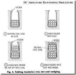
4. Use of slot feeders as insulation between windings. On armatures which operate on voltages higher than 110-120 volts, it is neces sary to insulate between windings in the slits and between the overlapping end turns of the windings. The procedure outlined below gives the steps to be taken in using the insulation feeders for insulating between windings. Fig. 5. After a coil side is placed into a slot:
a. Trim down the height of the coil-feeder insulation on both sides so that, when it is turned into the slot, it will be wide enough to cover the winding and fit into the slot. Fig. 5, step 1.
b. Bend one side of the trimmed feeder insulation into the slot
with a stiff fiber drift and press firmly into place, Fig. 5, step 2.
c. Bend the other side of the trimmed feeder insulation into the
slot over the top of the first side and press firmly into place with a stiffer fiber drift, Fig. 5, step 2.
d . Place a section of feeder insulation, cut to the proper dimen sions, over the top of the first, Fig. 5, step 3.
e. Proceed with the second coil according to the type of winding required.
f. Bend feeder insulation into the slot and wedge, Fig. 5, step 4.


