An electrical generator is a machine which converts mechanical energy (or power) into electrical energy (or power).
The energy conversion is based on the principle of the production of dynamically (or motionally) induced e.m.f. As seen from Fig. 26.1, whenever a conductor cuts magnetic flux, dynamically induced e.m.f. is produced in it according to Faraday’s Laws of Electromagnetic Induction. This e.m.f. causes a current to flow if the conductor circuit is closed.
Hence, two basic essential parts of an electrical generator are (i) a magnetic field and (ii) a conductor or conductors which can so move as to cut the flux.
Cut-away view of dc generator
Simple Loop Generator
Construction
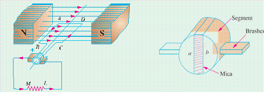
In Fig. 26.1 is shown a single-turn rectangular copper coil ABCD rotating about its own axis in a magnetic field provided by either permanent magnet is or electromagnets. The two ends of the coil
Fig. 26.1
are joined to two slip-rings ‘a’ and ‘b’ which are insulated from each other and from the central shaft. Two collecting brushes (of carbon or copper) press against the slip-rings. Their function is to collect the current induced in the coil and to convey it to the external load resistance R.
The rotating coil may be called ‘armature’ and the magnets as ‘field magnets’.
Working
Imagine the coil to be rotating in clock-wise direction (Fig. 26.2). As the coil assumes successive positions in the field, the flux linked with it changes. Hence, an e.m.f. is induced in it which is
proportional to the rate of change of flux linkages (e = NdFdt). When the plane of the coil is at right angles to lines of flux i.e. when it is in position, 1, then flux linked with the coil is maximum but rate of change of flux linkages is minimum.
It is so because in this position, the coil sides AB and CD do not cut or shear the flux, rather they slide along them i.e. they move parallel to them. Hence, there is no induced e.m.f. in the coil. Let us take this no-e.m.f. or vertical position of the coil as the starting position. The angle of rotation or time will be measured from this position.
Fig. 26.2 Fig. 26.3
As the coil continues rotating further, the rate of change of flux linkages (and hence induced e.m.f. in it) increases, till position 3 is reached where q = 90º. Here, the coil plane is horizontal i.e. parallel to the lines of flux. As seen, the flux linked with the coil is minimum but rate of change of flux linkages is maximum. Hence, maximum e.m.f. is induced in the coil when in this position (Fig. 26.3).
In the next quarter revolution i.e. from 90º to 180º, the flux linked with the coil gradually increases but the rate of change of flux linkages decreases. Hence, the induced e.m.f. decreases gradually till in position 5 of the coil, it is reduced to zero value.
So, we find that in the first half revolution of the coil, no (or minimum) e.m.f. is induced in it when in position 1, maximum when in position 3 and no e.m.f. when in position 5. The direction of this induced e.m.f. can be found by applying Fleming’s Right-hand rule which gives its direction from A to B and C to D. Hence, the direction of current flow is ABMLCD (Fig. 26.1). The current through the load resistance R flows from M to L during the first half revolution of the coil.
In the next half revolution i.e. from 180º to 360º, the variations in the magnitude of e.m.f. are similar to those in the first half revolution. Its value is maximum when coil is in position 7 and minimum when in position 1. But it will be found that the direction of the induced current is from D to C and B to A as shown in Fig. 26.1 (b). Hence, the path of current flow is along DCLMBA which is just the reverse of the previous direction of flow.
Therefore, we find that the current which we obtain from such a simple generator reverses its direction after every half revolution. Such a current undergoing periodic reversals is known as alter- nating current. It is, obviously, different from a direct current which continuously flows in one and the same direction. It should be noted that alternating current not only reverses its direction, it does not even keep its magnitude constant while flowing in any one direction. The two half-cycles may be called positive and negative half-cycles respectively (Fig. 26.3).
For making the flow of current unidirectional in the external circuit, the slip-rings are replaced by split-rings (Fig. 26.4). The split-rings are made out of a conducting cylinder which is cut into two halves or segments insulated from each other by a thin sheet of mica or some other insulating material (Fig. 26.5).
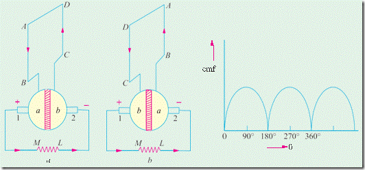
As before, the coil ends are joined to these segments on which rest the carbon or copper brushes. It is seen [Fig. 26.6 (a)] that in the first half revolution current flows along (ABMNLCD) i.e. the brush No. 1 in contact with segment ‘a’ acts as the positive end of the supply and ‘b’ as the negative end. In the next half revolution [Fig. 26.6 (b)], the direction of the induced current in the coil has reversed. But at the same time, the positions of segments ‘a’ and ‘b’ have also reversed with the
Fig. 26.4 Fig. 26.5
result that brush No. 1 comes in touch with the segment which is positive i.e. segment ‘b’ in this case. Hence, current in the load resistance again flows from M to L. The waveform of the current through the external circuit is as shown in Fig. 26.7. This current is unidirectional but not continu- ous like pure direct current.
Fig. 26.6 Fig. 26.7
It should be noted that the position of brushes is so arranged that the change over of segments ‘a’ and ‘b’ from one brush to the other takes place when the plane of the rotating coil is at right angles to the plane of the lines of flux. It is so because in that position, the induced e.m.f. in the coil is zero.
Another important point worth remembering is that even now the current induced in the coil sides is alternating as before. It is only due to the rectifying action of the split-rings (also called commutator) that it becomes unidirectional in the external circuit. Hence, it should be clearly under- stood that even in the armature of a d.c. generator, the induced voltage is alternating.


