Introduction
MAIN AND ROD BEARINGS
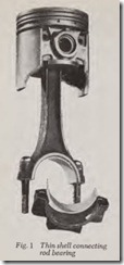
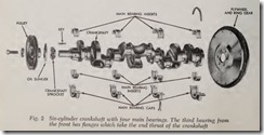
Main and connecting rod bearings used in all modern engines consist of two semi-circular halves usually referred to as bearing inserts or shells, Figs. 1 and 2. Each shell is made up of a steel back coated on its inner surface with a thin layer of babbitt. Babbitt is a bearing alloy contain ing about 90% tin, 5% antimony, 4% copper and small amounts of other metals. Other babbitt al loys may have somewhat different composition. There are other bearing alloys in use which con tain cadmium, lead and copper; aluminum is also used as a bearing surface in some modern engines. Thes e bearings have a total thickness of approxi mately 1/16″ with the bearing surface material approximating .003″.
Bearings should last upwards of 100,000 miles provided that: ( 1) Engine is run at correct oper ating temperature, ( 2) there is unfailing lubrica tion by clean oil of good quality, ( 3) not much driving is done at excessive speed, ( 4) the bear ings were in perfect condition at the beginning with respect to materials, fit and workmanship.
As long as the bearings and journals are smooth and true and constantly separated by an oil film, the rate of wear is very slow. But if the oil film fails to separate the bearing surfaces even for a few seconds, damage will be done. Failure of the oil film may be due to lack of oil, low or no oil pressure, or excessively thin oil.
If the lack of an oil film permits the journal and its bearing to rub together, rapid wear results and in fact the heat caused by the high friction may melt the babbitt almost instantly, thus ruining the bearing and causing a knock.
Rapid bearing wear may be caused by fine, hard gritty particles such as road dust floating in the air. These particles are hard enough to wear away the bearing journals as well as the bearings. The particles get into the oil in one of two ways. They may enter the engine by way of the car buretor and make their way past the pistons to the crankcase. Or they may enter by way of the crankcase ventilating system.
Bearings wear faster than their journals because they are made of much softer material.
Rod bearings wear faster than main bearings because they are the most heavily loaded . They have to withstand the high combustion pressure as well as the high inertia pressures resulting from the pistons moving up and down through the cylinders at 2,000, 3,000 or even 4,500 revolutions per minute.
Bearing trouble can be avoided by keeping the air cleaner, and the cleaner on the crankcase ventilating system clean, and by changing the oil filter cartridge and the oil before it becomes dirty or badly diluted or otherwise contaminated.
Because bearings are so frequently forced to operate under adverse conditions, they should always be checked for wear when new piston rings are installed.
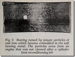
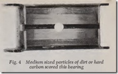
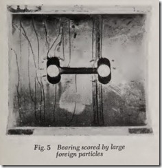
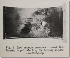
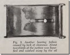
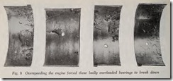
There are three principal reasons for bearing work. ( 1) Excessive oil leakage from worn bear ings which causes increased oil consumption. ( 2) Bearings have damaged surf aces. ( 3) Bearings are so badly worn that they cause a knock. Var ious kinds of bearing damage are illustrated in Figs. 3 to 11.
If oil pressure is 5 or 10 pounds below normal when the engine is warm, it may indicate that an excessive amount of oil is escaping from the bear ings because they are too loose. Normal oil pres sure for all modern engines is 30 to 50 pounds per square inch. But remember that there are other causes of low oil pressure.
Crankshaft and Bearing Service
BEARING OIL LEAK DETECTOR
Leakage is assumed to be excessive if oil pres sure is below normal or if bearing clearances are somewhat greater than they should be.
Oil leakage increases very rapidly with increase in bearing clearance. For example, in a certain engine where specified b earing clearance is .0015″ the leakage is at a satisf actory minimum. If we say this leakage rate is equal to 1, a clearance of .003″ gives 5 times the leaka ge while .006″ clearance permits 25 times the leakage, Fig. 12.
The only sure way to determine the amount of leakage is to use a bearin g leak detector. With it, the amount of leakage at each bearing can be seen. Guesswork is eliminated.
Without the aid of a leak detector, objection ably leaky bearings may be overlooked and on the other hand bearings in satisfactory condition may be discarded because the repairman does not want to risk the possibility of doing a ring or piston job only to find that oil consumption is still too high because of leaky bearings.
The leak detector can also be used to determine whether newly installed bearings are too tight ortoo loose.
If the leakage at a given bearing is 15 to 20 drops per minute (at 25 pounds pressure) the bearing is in good condition. The bearing may still be considered serviceable if the leakage is from 30
to 120 drops per minute. If leakage is less than 15 drops, either the oil passage to this bearing is clogged or the bearing is too tight. Leakage of more than 120 drops per minute indicates a worn bearing, which should be replaced with a new one.
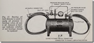
A typical oil leak detector is shown in Fig. 13. It is a compact, easily handled unit with an oil tank a little more than a foot long. It is filled with SAE 20 oil to the level of the filler plug. The hose at the right is connected to the engine oil pressure sys tem. The left hose is attached to the shop air line. A pressure reducing valve reduces the air pressure to 20 to 25 pounds. To use the detector, remove the oil pan so that the leakage can be observed .
Connect the leak detector oil hose to the engine lubricating system. It may be attached at the front where the oil gauge pipe connects with the block or at the oil pressure switch.
Open the shut-off cock which admits air into the oil tank. Adjust the pressure reducing valve until the gauge on the tank reads 20 to 25 pounds. Open the oil cock and check the pressure gauge. Readjust the pressure reducing valve to 20-25 pounds, if necessary. As testing. proceeds, check gauge pressure and readjust as required.
To catch the oil that leaks from the bearings, use a suitable pan, the length and width of the crankcase, or cover the floor underneath the crank case with an oil-absorbing compound or fine saw dust.
Leakage of main bearings and camshaft bear ings can be determined with the crankshaft in any position. Full oil pressure is supplied to these bearings continuously throughout each revolution regardless of crankshaft position. But this is not true of rod bearings. Remember that the rod bear ing is fed by a drilled passage in the crankshaft which registers once every revolution with the oil channel which supplies the adjacent main bearing. Therefore oil pressure to the rod bearing is only at maximum when the crankshaft oil passage lines up with its supply channel.
If the leak detector indicates loose bearings, new bearings should be installed.
When a bearing job is finished, it is a wise precaution to use a leak detector to determine whether bearing leakage is within reason.
BEARING TROUBLES
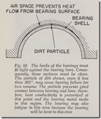
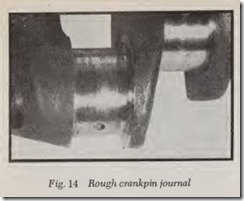
If one rod bearing knocks, it may be a sign of failure of additional bearings because of faulty lubrication. On the other hand, the lack of lubrica tion may be due to clogged oil passages leading to this bearing, in which case all or most of the other bearings will be undamaged. Other causes of fail ure of one rod bearing are: ( 1) Binding between bearing and journal due to too tight a fit or to a misaligned rod. ( 2) A slug of abrasive particles which by chance are delivered only to this bearing -and score the bearing. ( 3) Defect in manufac ture of this bearing. ( 4) Out-of-round rod bore. ( 5) Dirt between rod bore and bearing shell revents pr per seating of bearing. ( 6) Bearing rmproperly mstalled. ( 7) Slightly loose rod cap. ( ) New bearing installed on rough crankpin, F1g. 14, crankpin out-of-round or tapered too much.
Similar considerations apply to main bearings.
BEARING KNOCKS
If rod bearings knock, the upper and lower halves should be replaced. Sometimes just one rod will fail-of ten because of a clogged oil passage leading to this bearing. If so, the other rod bear ings may be okay-but be sure to inspect them and check for wear. Clean out the oil passages in the crankshaft as described further on.
If rod bearings are worn, the lower halves of the main bearings should also be inspected. If the lower halves are okay the upper halves can be assumed to be in good condition. However, if the lower halves must be replaced the upper halves must also.
If one main bearing develops a knock it may be caused by a clogged oil passage to this bearing, in which case all other bearings may be okay. How ever, to be on the safe side all main and rod bear ings should be inspected and their clearances checked.
If rod bearing wear is suspected because of low oil pressure and high oil consumption-and if an oil leak detector is not available-looset’tess of rod bearings can often be determined by shaking the rod. But even if looseness is not evident, bearing clearance should be checked by methods which will be described shortly.
Always check rod bearing clearances when do ing a ring job. If the bearing clearance is satis facto.ry-as explained further on-inspect the beanngs for faults. The bearing surfaces should be smooth and free of blemishes such as deep scratches, pits, melted or broken metal, as indi cated in Figs. 3 to 11. If any of these faults are noted the bearings should be discarded.
CHECKING CRANKSHAFT FOR WEAR
Before checking bearings for wear, the crank shaft journals should be inspected for surface smoothness, nicks, and for out-of-round and taper. If this checking indicates that the journals must be reground, there is no need to check bearing clear ances for wear since the reground shaft requires new undersize bearings, Fig. 14.
Rod journals can be reground without removing the crankshaft by portable equipment, whereas regrinding of the main bearing journals requires removal of the crankshaft because the work must be done in a special crankshaft grinding machine.
The rod and main bearing journals should also be inspected for smoothness. If the journal surface is scored or pitted the journal should be reground unless the rod journals can be smoothed up with a lapping tool if the indentations are not too deep.
A good test for satisfactory journal smoothness is to rub the tips of the fingers over the surface. If the roughness can be felt, reduced bearing life will result and lapping or grinding of the crank shaft is called for.
After a crankshaft has been reground, check the smoothness by rubbing a penny lengthwise of the journal. If a copper line shows on the journal, it should be lapped smooth.
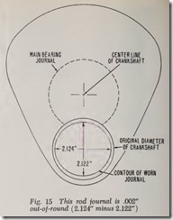
In the case of a rod bearing journal, note that the loads imposed on the journal are greatest in the region of upper and lower dead center. There fore with the rod at dead center, journal wear will be greatest in the up-and-down direction and least in the crosswise direction, Fig. 15.
To measure the journal, bring it to the lower dead center position and mike it up-and-down and crosswise at the middle of the journal. The difference between the two measurements is the amount of out-of-round. For example, if the cross wise diameter is 2.124″ and the vertical diameter is 2.122″, the out-of-round is .002″, Fig. 15.
The journal should also be miked at both ends on the vertical diameter to determine taper.
For maximum bearing life, obviously out-of round and taper should be negligible. Also the greater the out-of-round and taper, the more the bearing life is reduced.
For excellent bearing life, out-of-round should not exceed .001″ and taper should be less than .1 “-preferably much less. This means that the crankshaft should be reground if taper exceeds
.001″.
Practical experience proves that very good bear ing life is obtained when the out-of-round does not exceed .0015″ and taper is not more than .001″.
“MIKING” ROD JOURNALS
The first thing to do is use a micrometer to measure the amount of out-of-round and taper of the rod journals (also called crankpin journals).
Taper is likely to be greater at the vertical diameter, Fig. 15, therefore measure the vertical diameter at both ends of the journal. On a given engine with rod journals a nominal size of
2 “, the vertical diameter of one end of the journal might be 2.1235″ and the other end 2.1230″. The taper is the difference between these two dimensions, or .0005”.
A rod journal wears more rapidly on its vertical diameter. Therefore the horizontal diameter of a worn journal is always greater than the vertical diameter. Measure the horizontal and vertical di ameters near the middle of the journal. The hori zontal diameter might be 2.124″ and the vertical diameter 2.123″. The difference between the two diameters is the out-of-round .001″ in this case. Therefore the journals do not need regrinding provided their surfaces are smooth because .0015″ is usually considered the out-of-round limit.
However, assume that the horizontal diameter is 2.1237″ and the vertical diameter is 2.1216″. The difference (out-of-round) is .0021″. The jour nal is .0006″ over the usual out-of-round limit of
.0015″. The crankshaft should be reground.
“MIKING” MAIN BEARING JOURNALS
If the crankshaft has been removed from the engine, an outside micrometer can be used.
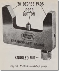
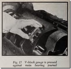
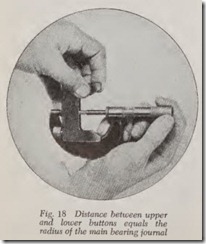
However, it is often desirable to mike the main journals with the crankshaft in place. The V-block gauge, Figs. 16, 17, 18, permits miking all crank shafts whether in place or removed from engine.
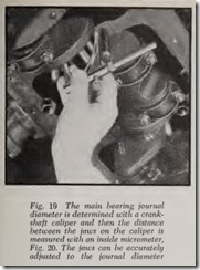
The crankshaft caliper, Figs. 19 and 20 can be used if the upper halves of the main bearings can be removed.
Whenever the crankshaft is miked in place by either of these methods, be sure that it is properly supported by its bearings. Either remove and replace the caps one by one, or remove all the intermediate caps and mike their journals. Then put these caps back and remove the end caps.
The V-block gauge, Figs. 16, 17, 18, consists of two pads which make a 30-degree angle with its center line. The upper button, as it is called, is really a spring backed plunger locked by tighten ing the knurled nut.
To use the gauge, loosen the knurled nut, press the plunger all the way down and lock it by tightening the knurled nut. Place the V pads in firm contact with the journal, Fig. 17. Hold it there with one hand and loosen the nut with the other until the plunger clicks against the journal. While still holding the gauge tight, lock the plunger by tightening the nut. Measure the dis tance between plunger and button with a microm eter, Fig. 18. This distance equals the radius of the crankshaft. Multiply the reading by two to obtain the diameter.
Be sure the micrometer adjustment is accurate because any error in measuremen t is doubled. All surfaces must be perfectly clean before using the gauge to avoid error in measurement.
WHAT SIZE BEARINGS TO USE
Replaceable main and rod bearings are gen erally available in the standard size and under sizes of .001″, .002″, .010″, .020″, and up in some cases.
Automotive machine shops have semi-finished bearings which can be machined to any desired undersize up to .060″.
If a crankshaft is reground it is customary to remove .010″ of metal and fit .010″ under size bearings unless a greater undersize is necessary to smooth up badly damaged journals. In some cases where too great a cut is require d to clean up a journal , it is advisable to build up the journal with metal and regrind it to the standard size, a job that is often done by operators of large fleets of vehicles.
The standard size bearing and the .001″ and undersize bearings are intended for installa tion on crankshafts which do not require regrind ing.
METHODS OF CHECKING BEARING CLEARANCE
There are three methods of checking rod and main bearing clearances: ( 1) Shim method, ( 2) Plastigage method, ( 3) Micrometer method.
If main bearings are checked by the Plastigage method with the engine in the chassis, the crank shaft must be supported in order to take up clearance between the upper bearing insert and crankshaft journal. This can be done by tightening bearing caps of adjacent bearings with .005″ to .015″ cardboard (such as a calling card) between lower bearing shell and journal. Use extreme care when this is done to avoid unnecessary strain on the crankshaft and bearings or a false measure ment may be obtained. Be sure to remove card board.
Checking Clearance by Shim Method
We know that a standard size bearing will fit but if the journal is worn it may give more clear ance than necessary. So the preference is for a .002″ undersize bearing if it will fit, or a .001″
undersize bearing, assuming that the .002″ under size is too tight and the standard size allows more clearance than needed.
Fig. 21. Its width should be J£” and its length should be slightly less than the length of the bearing. Most shops use a .002″ shim thickness. The edges of the shim should be smooth and free from burrs. Install a new .002″ undersize bearing in the rod and cap and coat it with clean engine oil. Lubricate the shim with engine oil and place it lengthwise in the bottom of the rod bearing cap. Install the rod on the crankshaft and draw the nuts up to specified torque wrench tightness. Turn the crankshaft by hand through one revolution. If there is a slight drag, the bearing fit is okay. If there is no drag, the bearing clearance may be less than ideal but still fairly satisfactory.
The “loose” bearing, however, should be rea sonably satisfactory provided the clearance is not more than .004″. Therefore, try a piece of .004″ shim for drag. Both car and bearing makers are reluctant to state positively what the maximum permissible bearing clearance is. But one of the best of them gives a maximum worn clearance of .0045″ for rods and mains. Maximum clearance for new bearings on this make of car is .002″. Also note that many car makers specify a maximum clearance for new bearings of .003″. Therefore the .004″ figure does not seem excessive.
Instead of turning the crankshaft to determine rod bearing drag, the rod bearing may be checked for fit by tapping it lightly with a hammer to move it lengthwise of the rod journal. If only a light tap is required the fit is not too tight.
When the fit of the .002″ undersize bearing is checked with a .002″ shim, if the drag is heavy instead of light, the bearing is too tight.
Therefore, try a .001″ undersize bearing. Use a .002″ shim as before. If drag is heavy instead of light a standard size bearing must be used.
Regardless of the size of bearing used it is a good plan to be sure that the new bearing is per fectly free on its journal when the shim is removed and the rod installed. Move it back and forth lengthwise by hand. If it is not perfectly free, remove the rod bearing and find out why. It may be binding at the edges or it may be the wrong size.
If brass or copper shim stock is not handy, paper may be used instead. Paper also has the advantage that there is no danger of marring the bearing. Mike up various thicknesses of paper which are handy. Use a strip of paper } ” wide and slightly shorter than the length of the bearing. Wet it with oil before using.
The .002″ shim stock which is generally used is conservative. It insures plenty of clearance. There isn’t much danger of fitting the bearings too tight. It conforms to the machinist’s rule of thumb that bearing clearance ought to be .001″ for each inch of bearing diameter.
However, a .0015″ shim is likely to do a more accurate job than a .002″ shim. A rod or main bearing clearance of .0015″ is within the clearance range of most car engines.
The virtue in using a .0015″ shim is simply that a .002″ shim may tell you that a .002″ undersize bearing is too tight whereas the .0015″ shim may indicate the .002″ undersize is okay. Therefore if you are guided by the .002″ shim you may decide to use a standard size bearing when you would be better off with .002″ undersize. To a lesser degree this also applies to .001″ undersize bearings.
