STEP CONTROL
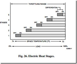
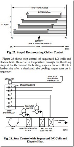
Step controllers operate switches or relays in sequence to enable or disable multiple outputs, or stages, of two-position devices such as electric heaters or reciprocating refrigeration compressors. Step control uses an analog signal to attempt to obtain an analog output from equipment that is typically either on or off. Figures 26 and 27 show that the stages may be arranged to operate with or without overlap of the operating (on/off) differentials. In either case, the typical two-position differentials still exist but the total output is proportioned.
Figure 28 shows step control of sequenced DX coils and electric heat. On a rise in temperature through the throttling range at the thermostat, the heating stages sequence off. On a further rise after a deadband, the cooling stages turn on in sequence.
A variation of step control used to control electric heat is step-plus-proportional control, which provides a smooth transition between stages. This control mode requires one of the stages to be a proportional modulating output and the others, two-position. For most efficient operation, the proportional modulating stage should have at least the same capacity as one two-position stage.
Starting from no load, as the load on the equipment increases, the modulating stage proportions its load until it reaches full output. Then, the first two-position stage comes full on and the modulating stage drops to zero output and begins to proportion its output again to match the increasing load. When the modulating stage again reaches full output, the second two- position stage comes full on, the modulating stage returns to zero, and the sequence repeats until all stages required to meet the load condition are on. On a decrease in load, the process reverses.
With microprocessor controls, step control is usually done with multiple, digital, on-off outputs since software allows easily adjustable on-to-off per stage and interstage differentials as well as no-load and time delayed startup and minimum on and off adjustments.
Floating control
Floating control is a variation of two-position control and is often called “three-position control”. Floating control is not a common control mode, but is available in most microprocessor based control systems.
Floating control requires a slow-moving actuator and a fast- responding sensor selected according to the rate of response in the controlled system. If the actuator should move too slowly, the controlled system would not be able to keep pace with sudden changes; if the actuator should move too quickly, two-position control would result.
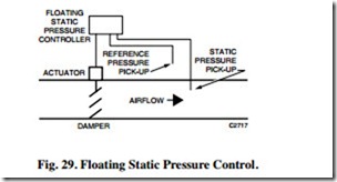
Floating control keeps the control point near the setpoint at any load level, and can only be used on systems with minimal lag between the controlled medium and the control sensor. Floating control is used primarily for discharge control systems where the sensor is immediately downstream from the coil, damper, or device that it controls. An example of floating control is the regulation of static pressure in a duct (Fig. 29).
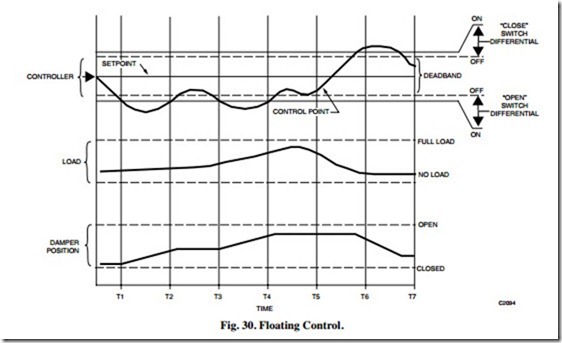
In a typical application, the control point moves in and out of the deadband, crossing the switch differential (Fig. 30). A drop in static pressure below the controller setpoint causes the actuator to drive the damper toward open. The narrow differential of the controller stops the actuator after it has moved a short distance. The damper remains in this position until the static pressure further decreases, causing the actuator to drive the damper further open. On a rise in static pressure above the setpoint, the reverse occurs. Thus, the control point can float between open and closed limits and the actuator does not move. When the control point moves out of the deadband, the controller moves the actuator toward open or closed until the control point moves into the deadband again.


