3 ·6 AUTOMATIC MOTOR STARTERS
The automatic starter, also known as a magnetic starter, consists of a contactor with the addition of protective control. This starter depends upon the magnetic pull of an electromagnet to close and hold its line and auxiliary contacts and offers unlim ited flexibility of control. It is dependable and has a long life expectancy with reasonable maintenance. There are many me chanical arrangements used on this type of starter. They fall into two general classifications, however, depending on the movement of the magnetic coil core.
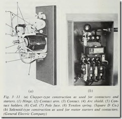
The first of these is the clapper type (Fig. 3 ·11a) which has the movable contacts attached to the hinge along with the mag netic core or a section of the core. The hinge is so arranged that the pull of the magnetic circuit swings the pole piece and the contacts in a more or less horizontal direction, and the sta tionary line contacts are mounted on the vertical backboard of the starter.
The second is the solenoid type (Fig. 3 ·11b) . With this type, the contacts are mounted to the movable portion of the core so that when the core closes, the movable contacts move to meet the stationary contacts.
Either of these basic types seems to be satisfactory, although each manufacturer has some reason for the particular type em ployed in his units.
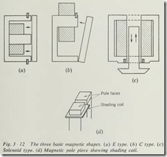
The all-important magnetic circuit consists generally of an adaptation of one of the three basic magnetic shapes (Fig. 3 ·12). The E or C type is used on most clapper-type starters, and the modified E or solenoid type is used on vertical-action starters.
When a-c coil circuits are used, the pole faces of the magnet are equipped with a shading coil (Fig. 3 ·12d). This gives an out-of-phase flux to hold the magnet closed during the zero points of current, thus preventing chatter of the contacts. While this method of preventing chatter is effective, many starters for large motors employ a d-e coil circuit because of its constant magnetic pull and freedom from any tendency to chatter.
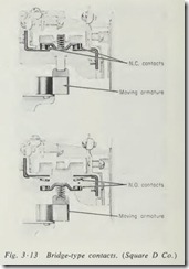
There are also two basic types of contacts in general use. Most small starters employ a bridge-type contact (Fig. 3 ·13). The bridge-type contact offers good contact alignment and a natural wiping action which helps to prolong contact life. Most large starters employ the required number of spring-mounted movable contacts that meet a corresponding number of rigid stationary contacts (Fig. 3 ·11a).
The necessary wiping action is obtained by making the contacts in a curved shape that allows them to slide into alignment as they close and open. Good con tact alignment is necessary in order to prevent excessive arcing and contact pitting .
The greatest single contribution to modern-day production machinery is the magnetic starter. The flexibility of control offered by the magnetic starter allows automation and automatic control accuracy never dreamed of, nor possible, with manual operation. This flexibility stems from the fact that all that is necessary to start a motor is to provide electric energy to the coil of the starter. The source of energy may be independent of the motor circuit and can be turned on and off from any point and by any means desired .
3 ·7 FULL-VOLTAGE STARTERS
Full-voltage, or across-the-lin e, starters (Fig. 3 ·11b) are the most widely used type. They are used on almost all three-phase, squirrel-cage, and single-phase motors. This type of starter is also used extensively as primary control on wound-rotor motors that employ manual secondary control. Rated for use on motors up to 600 hp and up to 600 volts, they can give full protection to the motor, the machine, and the operator. The limitation on the use of this starter for squirrel-cage motors is only the strain imposed on the wiring system and the machine by the starting current and torque of the motor. Across-the-line starters are available in a variety of enclosures to meet the needs of starter location conditions . These enclosures conform to the standards published by the NEMA to suit every condition of location. Availability also in either manual or magnetic types to suit the customer’s needs adds to the flexibility of these units.
Any starter which connects the motor leads directly to the line voltage without any means of reducing the applied voltage or limiting the starting current would be classed as a full-voltage starter.
3 ·8 REDUCED-VOLTAGE STARTERS
As the name implies, the reduced-voltage starter contains some means of reducing the line voltage as it is applied to the motor during the starting period. This is done in order to limit the inrush of current during the starting cycle. The requirements for using reduced-voltage starting depend upon several factors (Sec. 2 ·1). These units are built in either manual or automatic types, and, as with full-voltage starters, the manual type 1s cheaper but less flexible.
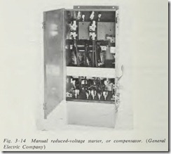
Manual reduced-voltage starters for squirrel-cage motors, more commonly referred to as compensators (Fig. 3 ·14), consist of a double-throw switch and an autotransformer. The START position of the switch applies power to the motor through an autotransformer. The operating handle is held in this position until the motor is running at the highest speed it will attain, and full voltage is then applied by throwing the handle to the RUN position. The switch mechanism is held in the RUN position by a latch which can be released by either the undervoltage release, the overload units, or the hand trip. Generally, these units are in a self-contained metal enclosure that is designed to be wall-mounted .
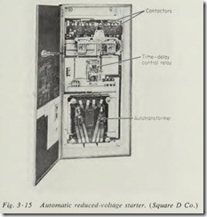
Automatic reduced-voltage starters (Fig. 3 ·15) take many forms and are generally designed for a particular type of motor and for a particular application . The essential requirements are that some means be provided for connecting the motor to a source of reduced voltage and then automatically connecting it to the full line voltage after it has had time to accelerate.
The start contactor on a primary-resistance starter need be only a three-pole unit. This contactor connects the motor to the line in series with resistor units designed to limit the motor
starting current. The run contactor in this starter is also a three pole unit which shorts out the resistors in order to apply full voltage to the motor.
The reactor type of reduced-voltage starter employs exactly the same contact arrangement as the primary-resistance starter. The only difference between a starter for primary resistance and a reactor type of reduced-voltage starter is in the use of reactors in place of the resistors.
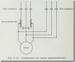
The start contactor for an autotransformer type of reducedvoltage starter must be a five-pole contactor. The use of these five contacts is shown in Fig. 3 ·16. These contacts connect the motor to the line through the autotransformer connected open delta. The run contactor in this starter consists of three contacts which apply full line voltage to the motor.
Regardless of its type, an automatic reduced-voltage starter must contain some means of automatically changing from START to RUN at the proper time. Generally, this is accompanied by the use of a time-delay relay (Sec. 3 ·3). In the case of primary resistance or reactance starters, this relay is required only to energize the coil of the run contactor. When used on an auto transformer starter, this relay must break the circuit to the start contactor and then make the circuit to the run contactor. The use of a time-delay relay in this service gives definite-time control (Sec. 2 ·2). Another method which is sometimes used employs a form of current relay (Sec. 3 ·3) which will open the start contactor and close the run contactor when the motor current drops to a predetermined level. This gives current-limit control (Sec. 2·2).
When primary resistance or the reactor type of reduced-volt age starting is employed, there is no interruption of current to the motor. With the autotransformer type of reduced-voltage starting, however, the current may or may not be interrupted momentarily before the motor is placed across the line. When the current is not interrupted in the transition from reduced-volt age to full-voltage operation, it is referred to as a closed-transi tion start. When the motor is disconnected momentarily from the line and the current interrupted, it is referred to as an open transition start. When the transition is of the open type, it is quite possible to have an inrush of current as high as twice the full-voltage starting current at the instant of voltage application. This surge of current is referred to as transition current.
Any of these controllers may contain almost any or all of the protection control functions, such as undervoltage release (Sec. 2 ·12), phase failure (Sec. 2 ·13), or incomplete sequence protection (Sec. 2 ·15).
One thing that you must keep in mind when choosing between manual and automatic controllers of this type is that when a manual unit is installed, it must be located so that the operator can not only see but also hear the motor, in order that he may properly judge when to apply full voltage. This limited selection of location can be overcome to some extent by installing a re mote indicating tachometer. This enables the operator to deter mine the degree of acceleration of the motor from the control location.
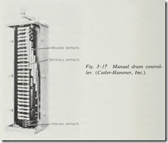
Another method of obtaining the effect of reduced-voltage starting is to use a wou nd-rotor motor with secondary control. This arrangement gives a higher starting torque with reduced starting current than does the squirrel-cage motor on primary reduced-voltage starting. The starter for such an arrangement would consist of an across-the-line starter connected to the pri mary of the motor. The secondary, or rotor, winding of the motor is connected to resistance grids by means of either a man ual or automatic drum controller (Fig. 3 ·17). A second advan tage to this arrangement is that it can offer speed control as well as limited starting current.
3 ·9 SPEED-CONTROL STARTERS
Besides the secondary speed control of wound-rotor motors, there are methods of controlling the speed of squirrel-cage motors, provided they are designed for multispeed operation.
One type of two-speed motor is wound with two separate stator windings and requires a starter with two sets of line con tacts which can close only one set at a time. This interlock (Sec. 2 ·10) may be either mechanical or electrical or both. Two separate across-the-line starters may be used with electrical interlock when a special unit is not available. A reversing starter makes an excellent unit , provided the reverse phasing is elimi nated. The two sets of contacts or starters are wired so that each set connects one speed winding to the line. As in other types of starters, they may be either manual or automatic.
Another type of two-speed motor is the consequent-pole motor, which has only one stator winding but gives two speeds by means of regrouping the stator coils to provide for a different number of poles. While the dual-stator-winding motor might have almost any ratio of high to low speed, the consequent-pole motor gives a 2 to 1 speed ratio. Three speeds may be obtained by using two stator windings. One of these windings gives one speed, and the other is regrouped for a second and third speed. To obtain four speeds, both windings must be regrouped. To obtain multispeed and variable torque, the high-speed windings are connected parallel-star and the low-speed windings are con nected series-star (Fig. 2 ·3).
For constant horsepower and multispeed, the connection should be series-delta for high speed and parallel-star for low speed.
Because of the variety of possible connections, the starter for this motor must be designed for the particular type of motor to be used. One of the most popular manual arrangements re quires the use of a drum-type controller to make the necessary changes in connections. This controller, however, must be pre ceded by an across-the-line motor starter which is interlocked through a set of contacts on the drum controller. The interlocks must disconnect the motor whenever a speed change is made by rotating the drum controller. The use of the across-the-line starter also provides the necessary protection for the motor which is not available on the drum controller.
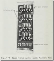
Magnetic starters for multispeed motors must have a contactor for each speed (Fig. 3 ·18). The contacts on each contactor must be so arranged that they will make the proper connections to the stator windings for the motor to be used. These starters can be built to give any one of three types of control. The first and simplest of these is selective speed control. With selective speed control, the operator may start the motor at any speed desirable and increase the speed merely by selecting any higher speed. To reduce speed, however, he must push the STOP button first and allow the machine to lose speed before the lower speed control is energized. This is done to prevent undue stress and strain on both the motor and the machine .
The second type is sequence speed control , which requires that the machine be started in its lowest speed and brought up to the desired speed through a set sequence . The acceleration
to the desired speed requires that the operator push the button for each speed in proper sequence until the desired speed is reached. To reduce speed, the motor must be stopped and the sequence started over at the lowest speed.
The third type is automatic speed control, in which the opera tion is like sequence speed control, except that the operator need push the button only for the desired speed. The controller will automatically start in the lowest speed and accelerate through each successive speed to the one selected. To reduce speed, the STOP button must be pushed first. Then the button for the new speed should be pushed, which will recycle the con troller to the new speed through each successive lower speed.
The choice of controller depends upon the type of load and the required operating conditions. Keep in mind that the basic difference lies in the fact that selective speed control aiiows starts in any speed, while the other two require a start at the lowest speed. It is not possible to describe properly the physical buildup of this type of unit in general terms , because of the many possible variations. In any case, however, a magnetic contactor will be required for each speed with the required number of contacts to make the connections for that speed plus the desired protec tion control. The possible automatic accelerations are discussed in Sec. 2 ·2, and any of these systems might be used.
