Capacitor Motors
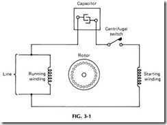
Capacitor motors are single-phase ac motors ranging in size from frac tional hp to perhaps as high as 15 hp. This type of motor is widely used in all types of single-phase applications such as powering machine shop tools (lathes, drill presses, etc.), air compressors, refrigerators, and the like. This type of motor is similar in construction to the split-phase motor (Chapter 2), except a capacitor is wired in series with the starting winding as shown in Fig. 3.1.
The capacitor provides higher starting torque, with lower starting current, than the split-phase motor, and although the capacitor is some times mounted inside the motor housing, it is more often mounted on top of the motor- encased in a metal compartment.
In general, there are two types of capacitor motors in use: the capacitor-start motor and the capacitor-start-and-run motor. As the name implies, the former utilizes the capacitor only for starting; it is dis connected from the circuit once the motor reaches running speed, or about 75o/o of the motor’s full speed. Then the centrifugal switch opens to cut the capacitor out of the circuit.
The capacitor-start-and-run motor keeps the capacitor and starting winding in parallel with the running winding at all times, providing quiet and smooth operation at all times.
As a rule, single-phase motors are used in sizes up to about 7.5 hp, and the capacitor-start motors are utilized for heavy-duty loads in resi dential and small commercial applications for which three-phase service is not practical or not available at all.
The capacitor-start motor is available in normal starting torque de signs for such loads as fans, blowers, centrifugal pumps, and similar applications. The high-starting torque designs are used on such equip ment as reciprocating compressors, pumps, loaded conveyors, and the like.
Capacitor split-phase motors require the least maintenance of all single-phase motors, but they have a very low starting torque, making them unsuitable for many applications. Their high maximum torque, however, makes them especially useful for such tools as floor sanders or in grinders where momentary overloads due to excessive cutting pressure are experienced. They are also used quite frequently for slow-speed direct-connected fans.
Refer to the diagram in Fig. 3-1; both the starting and running wind ings are connected across the line during the starting period since the centrifugal switch is closed. Note that the starting winding is connected in series with the capacitor and the centrifugal switch and remains in this position during the starting cycle. Then, when the motor reaches approx imately 75% of its full speed, the centrifugal switch opens, cutting out both the capacitor and starting winding from the line circuit.
The starting torque in a capacitor motor is produced by a revolving magnetic field which is established inside the motor. This magnetic field is accomplished by locating the starting winding 90 electrical deg out of phase with the running winding, causing the current in the starting winding to lead the current in the running winding. This condition produces a revolving magnetic field in the stator, which in turn induces a current in the rotor winding, producing rotation of the motor.
CAPACITORS
Physically, a capacitor consists of two conducting materials separated by an insulator. Its purpose is to oppose any change in voltage, and it has the ability to store electrical energy. When connected to an ac power supply-as in a capacitor-start motor-the plates will charge alternately positive and negative and give the illusion of current flow through the in sulating medium. Because of the charge-discharge cycle, the current must lead its voltage by 90 electrical deg enabling its power factor to be zero and consuming no power.
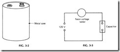
Capacitors are rated in microfarads ( JJ F), and the type most often used in motors is the electrolyte capacitor. This type of capacitor consists of two sheets of aluminum foil which are separated by one or more layers of gauze which have been saturated with a chemical solution called an electrolyte. See Fig. 3-2. This type of capacitor is suitable only for inter mittent duty and should not be held in a circuit for more than a few seconds at a time.
In checking capacitors, remove them from the circuit and then mea sure capacitance on a capacitance bridge if one is available. This test will detect either open or shorted capacitors. Measure the resistance of a capacitor with an ohmmeter. If the capacitor is shorted, the meter will indicate less than 10 n. If the capacitor is good, the resistance will be 50 Mn or greater.
To check for an open-circuited capacitor, connect as shown in Fig. 3-3. During this test, if the neon tester does not glow, the capacitor is de fective. This test, however, does not apply to mica grid capacitors. Resis tance between terminals, and between terminals and case, measured with a megohmmeter, should be at least 50 Mn. In the case of mica grid capacitors, check either on a capacitance bridge or try a new capacitor. For a short-circuit test of a mica grid capacitor, leave the capacitor on the tube socket, remove the external grid lead, and measure the resistance with an ohmmeter. It should show at least 100 Mn.
The main reasons for a capacitor becoming defective include the fol lowing: excessive use, overheating, and held in the circuit too long. In the case of capacitors for capacitor-start motors, a defective capacitor must be replaced with one of approximately the original value of capacitance, or the motor may not have the required starting torque for proper start ing and operation.

