Circuits
The previous chapter has listed the symbols representing electrical and electronic components. Symbols make a drawing or circuit more readable.
Generally, a schematic consists of a control and a power circuit. The power circuit provides power to the motors through contactors, whereas a control circuit controls these contactors through safety interlocks.
Reading a circuit
• All control devices such as switches and relay contacts are either NO or NC contacts.
• The switch position normally shown in any circuit diagram is the default de- energized condition state.
• For denoting sensor contacts notations such as LS, PS, TS are used.
• A relay coil is denoted with a symbol inside a circle and contacts of relay used in the circuit are represented with the same tag as the coil. If a relay coil has multiple NO and NC contacts then the contact identification numbers, as shown on relays, are mentioned in the drawing.
• In between the control supply lines L1 and L2 you will find either the relay coil or a solenoid coil or the lamp load.
• If several devices are to be turned ‘On’ at the same condition then you will find them connected in parallel between L1 and L2.
• If wires are common for two devices then in the diagram they are shown with the same identification number.
• Generally, power circuit conductors are shown with thick lines while thin lines are used for control circuits.
• A broken line indicates a mechanical function. Generally, it is used to show linkage between two different contacts of the same push button.
Different wiring diagrams
In order to troubleshoot electrical equipments two things are required. One is the location of the equipment to be tested and the other is the interconnection between all the devices (contactors, timers, relay).
The wiring diagram of electrical equipment gives information as stated above. In addition, it shows the identification tags of wires, connectors, relays, etc.
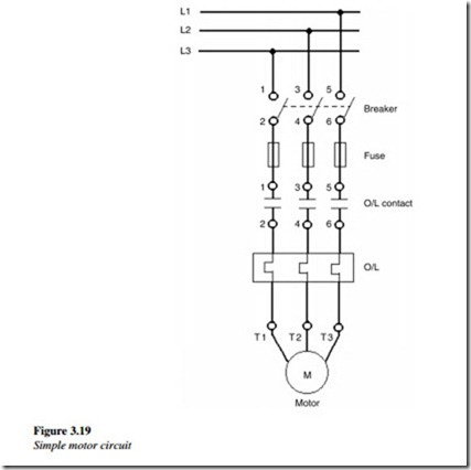
In Figure 3.19, the wiring diagram of a DOL starter is shown along with the physical location of the devices. The terminal numbers of overload relays are also shown in the wiring diagram. This enables accurate device wiring and wire tracing during troubleshooting.
Generally, this kind of wiring diagram is given inside an electrical equipment panel cover.
This diagram shows the actual position of different devices as closely as possible. The bold line indicates the heavy current carrying conductors, while the thin line indicates the control circuit.
