LOUDSPEAKER SYSTEMS
The end result of an audio system is to reproduce sound waves in space, with acoustic properties peculiar to each individual application. Hence, the choice of an appropriate loudspeaker system is of vital importance to the overall result. All that has been done in the electronic part of the system now relies on the loudspeaker system to successfully propagate the program into the space where it will be heard.
Every indoor installation must “live” with the acoustic characteristics of the room where it will operate. An outdoor installation is simpler, due to the absence of this problem, but it does have to withstand weather. Also, in general, it has to serve larger areas without help from reverberation—the containment of the sound.
HORNS
Outdoor speakers need the maxiumum efficiency, economic feasibility, and directivity so that sound is not wasted in directions where it is not needed or wanted. For these reasons, horns have become almost universal for outdoor installations: they provide natural weather protection; they are relatively high in efficiency; and they have a degree of directionality dependent on the constants in their design.
Horns come in all sizes and shapes, and are made of a variety of materials, metallic and plastic. Most of the smaller ones, suitable for paging, outdoor intercom, or low-level distribution, come with the driver unit as an integral part. The larger ones have removable drivers so that power can be increased, where necessary, by fitting a more powerful driver unit.
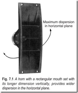
Metal horns are, in general, more rigid, but they do add a “tinny” quality to the reproduced sound. For many outdoor installations this is quite unimportant, as the sound is quite intelligible, which is the main requirement. Horns made of various plastic substances avoid the “tinny” sound, but may still give a trumpet-like effect, which is also quite acceptable in most outdoor installations. The directivity pattern depends more on the internal design of the horn than on its shape, as observed externally. A simple horn, with uniform development of the wave down its length, leading to a rectangular mouth opening, gives the widest dispersion across the narrower mouth dimension (Fig. 7.1). However, some directional horns are designed with changes inside the development that make it possible for the long dimension of the mouth to correspond with the direction of wider dispersion, which is psychologically what one expects.
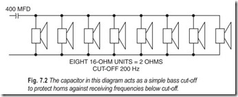
Horn size relates not only to power-handling capacity: even more directly it relates to low-frequency cut-off. Every horn has a low-frequency cut-off below which it will not operate. If appreciable power at any frequency below this is fed to the unit, it may result in damage, and it will not radiate appreciable sound at such frequencies. The smaller the horn, the higher the cut-off frequency. A wise precaution in any system using horns is to install a bass cut that prevents excessive signal reaching the horns at frequencies below cut-off. The simplest method is a simple capacitor in series with the output, which may be applied, either one in each speaker connection, or one for the whole system (where all horns are used).
The value of the capacitor (Fig. 7.2) should be calculated to have a reactance equal to that of the load (the horn impedance or combined impedance) at the cut-off frequency. Thus if all the horns have a cut-off of 200 Hz, and the system consists of eight 16 W units, the combined impedance is 2 W. A reactance of 2 W at 200 Hz requires a capacitor of 400 mfd. Smaller horns may have a cut-off at a higher frequency, such as 800 Hz. If they are each of 45 W impedance, and a system uses 15 of them, the combined impedance is 3 W. A capacitor to have 3 W reactance at 800 Hz must be about 67 mfd. A 50 mfd capacitor of suitable working voltage should serve.
The problem of achieving adequate audience coverage in situations where background noise create problems is more likely to arise in outdoor than indoor situations. Buildings provide some insulation against outside noises getting in, and the confines of the building enable sound energy to be conserved, rather than escaping to infinity as happens outdoors.
INDOOR ACOUSTICS
The variety of situations that can be encountered indoors is virtually infinite. Studies in acoustics have established certain ideal characteristics, according to building size and the purpose or kind of sound that will make up program. At best these provide only guidelines.
The ultimate sound reproduced is a quite complex wave system, propagated through space. In any indoor installation, every listener, or member of the audience, should hear first a direct sound at every component frequency, and then an appropriate amount of reverberation, or reinforcement of the same complex sound. If there is no reverberative reinforcement the sound seems unnatural; if there is too much of the direct sound, it is not strong enough to be intelligible.
Reverberation “happens” whatever you do. Sometimes, as in studios, structural or decorative designs can be used to adjust its amount to better suit the purpose of the sound system. But more often, especially in home high fidelity and stereo installations, the owner just wants to put the system in his room—he’s not about to redesign his room to suit the system. So we have to accept the room “as is” and find a way of achieving a good reproduction illusion in that environment.
In the living-rooms kind of environment, it seems as if nature is “on our side.” For smaller rooms the smaller speakers (such as the “bookshelf” variety) seem to do the better job, while for larger rooms the larger enclosures, such as corner horns, are better. But in case of larger installations there are more factors which affect the acoustics.
In the home system, room acoustics vary considerably; some rooms are carpeted, wall-to-wall; perhaps the windows are adorned with heavy drapes; and the condition is further augmented with an acoustic tile ceiling and plenty of well-stuffed furniture. Such a room is relatively dead acoustically. If you talk, the room gives the impression of being nice and quiet.
At the other end of the spectrum is the “empty” room, or one that sounds that way. The floor may be made up of tile or wood, the walls plaster or paneled, with a hard finish, and the ceiling completely nonabsorbent. The furniture may be devoid of upholstery, such as the wrought-iron frame type, with cloth draped over it like a sling. Such a room is acoustically live. If a number of people are holding simultaneous conversations in such a room, the effect can become quite nerve-wracking. For reproduced sound each kind of room needs its own treatment, for which different kinds of speaker systems are suited.
The reason why speaker size should be suited to room size, apart from the fact that the customer will usually prefer it that way, is that speakers tend to generate sound waves commensurate with their physical size. Of course, every frequency has its corresponding wavelength, and the speaker must have some way of developing waves of each wavelength in the audio spectrum. Large speakers require more space to develop the waves, particularly the lower frequency ones, than the smaller speakers. Consequently, placing a larger speaker in a relatively small room may not give the waves space to develop as the speaker designer intended. This is particularly true for corner horns, and to a lesser degree of bass reflex types.
STEREO SYSTEMS
As most home high fidelity systems are not stereo, we will devote this section directly to achieving the best stereo illusion in different type of rooms. For the medium-to-dead type of room with plenty of absorptive surfaces, the conventional stereo placement is best: two speakers are spaced apart so that their separate program content can be clearly heard through most of the room.
In a conventional rectangular room the speakers should be placed either in the corners at opposite extremities of one of the shorter walls, or a little way in from the corners along one of the longer walls (Fig. 7.3). Speakers types can be chosen to suit the situation. In a bigger room, large corner speakers may be best. In a smaller one, perhaps suitable placement for the “bookshelf” type can be found. But even in this type of room, sometimes the ideal placements are not practical. Not all rooms are rectangular the L–shaped room is very popular — and doors, windows, and fireplaces are often right where one of the speakers ought to be.
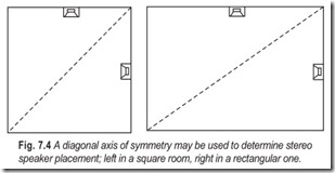
Perhaps an aid to understanding what we try to do in stereo is the concept of an axis of symmetry. In case of speakers at or near the extremities of one wall, the axis of symmetry bisects that wall and extends across the room, dividing it into two similar halves. In the case of a square room another perfect axis of symmetry would be a diagonal (Fig. 7.4). But in a rectangular room an approximate axis of symmetry could run from corner to corner, a similar diagonal. Putting the speakers on appropriate mid-sides gives a whole range of new possibilities for stereo placement.
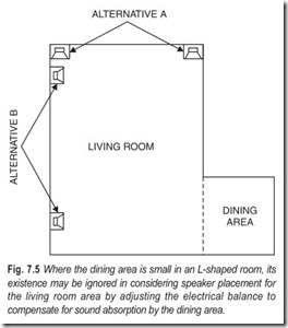
Rooms with L shapes or other deviations from the simple rectangular, pose a different kind of problem. But usually the simplest concept is to think of the shape as a modified rectangular. The basic rectangle, on which you base your notion of providing stereo, may be part of the whole room, or more than the whole room. For example, if the dining area is a relatively small area added on to
the living room, and people will not normally listen to stereo while dining, or will only treat it as incidental music if they do, the best approach is to ignore the existence of the dining area (Fig. 7.5).
The fact that some of the sound from one side, more than the other of the stereo, will spill over into the dining area may require a slight balance adjustment of the stereo controls, so the balance seems correct.
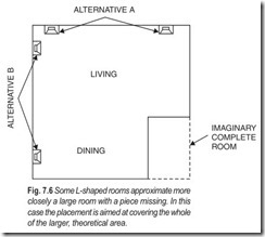
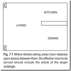
On the other hand, some L-shaped rooms could be more accurately approximated as a larger rectangle from which a small area is removed (Fig. 7.6). This is particularly true where the remaining area happens to be kitchen, which is only separated from the living-dining area by a counter-top, rather than a complete wall (Fig. 7.7). In either of these cases, it would be easier to consider that you are aiming to serve the entire, large rectangular area with stereo.
Where the room is far more live, as in the average recreation room, without carpets, drapes (heavy ones at least), or acoustic tile ceiling, or with only some of these, conventional treatment as suggested above may not give a very good stereo illusion because there is too much echo. In the dead rooms the aim is to serve the entire listening area with sound direct from both loudspeakers (with the possible exception of spill over areas). If sound doesn’t reach the listener directly, it’s apt to be lost, so sitting in a position where only one speaker can be heard will lose the stereo illusion. But in the live room, reflections tend to destroy the illusion if this approach is used. So the technique in a live room is to utilise the reflections, since you cannot easily get rid of them. One way to do this is to use a cabinet-type stereo with speakers on the ends of the cabinet (Fig. 7.8). This relies on reflections from the walls to get the apparent separation, rather than allowing the sound bounced off the walls to destroy it.
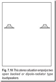
Another technique that works well in this kind of room, although it is not confined to this type, is the so- called dipole or planer-type speaker. All the speakers we have discussed to this point radiate what is basically a sound pressure wave, and the point where this wave enters the room, (or a reflection of it, in the case of Fig. 7.8) identifies the sound source for each channel. The dipole speaker doesn’t work in the same way. The back is completely open so that when the front pushes a sound compression out, the back sucks a sound rarefaction in. Listening to one of the speakers on monophonic program, as you walk around it, the back and front do not sound too different from conventional speakers. But when you get edge on, the location of the speaker suddenly seems to vanish (Fig. 7.9). You suddenly get the impression that the thing you’re looking on as a speaker isn’t working, and the sound must really be coming from somewhere else.
If two of these are used on stereo, one for each channel, and placed in a manner somewhat like that shown in Fig. 7.10, a completely new type of listening situation results. Now, in either end of the room, the stereo illusion is as good as it would be with the other type, similarly placed, but facing only toward you. If you used two for each channel, back-to-back, in a highly reflective room, you’d get too much reflection from the ones facing away from you via the far end of the room. But with dipole speakers placed like that in Fig. 7.10, not only do you get a good stereo illusion in both ends of the room, it is also good immediately between the speakers, although you would not identify the sources of sound with the speakers. However, you do get the separation, because of the interaction between the different program content in the two channels.
COST AND EFFICIENCY
The general methods of providing stereo for different kinds of rooms are already considered, but another important aspect which needs mention is cost and quality. And this in turn is related to efficiency, especially when size is taken into consideration. Small speakers can be highly efficient, provided their frequency response isn’t very low, since as small speakers become more effective at lower frequencies (bass) they lose efficiency.
Earlier books on this subject related quality and efficiency to magnet size—which is the most costly single part of a loudspeaker. However, with the newer ceramic magnets, this relationship is not quite so certain, because the magnet is no longer the vital cost element. And even if magnet size is considered an index of efficiency, this is true only up to a certain size, when other limitations stop a further rise in efficiency with increasing magnet size.
Obviously, if magnet size were the only factor in determining efficiency, this could rise no higher than 100%. After a magnet size sufficient to achieve 50% is reached, further improvement in efficiency would not be commensurate with the increase in magnet size and cost needed to achieve it. But when an objective, such as packing a speaker with good bass response into a small box, is taken into account, further basic limitation on efficiency is imposed, so that the theoretical ultimate might be 2% instead of 100% (which isn’t possible, in fact, because there is no solid substance as light as air which can be used to construct a diaphragm). Taking all these factors into account, a reasonable “high-efficiency” speaker—one of the larger variety—might run about 25% efficient. A low-efficiency speaker, one of the bookshelf variety, is more likely to run about 2% efficient.
Efficiency is not necessarily related to quality. This is a matter of how well the individual design is implemented. Usually, within the other limitations, improving efficiency within a given type goes along with improved quality, and also higher cost. But technology is advancing so rapidly that a low-cost, well-designed speaker of recent manufacture may be better than older ones costing far more, and on which possibly more design hours were spent!
Speakers for indoor applications, other than high fidelity or stereo in the home, are made to more competitive economic standards. Unless difficult conditions make it essential to get the maximum acoustic power, requiring a high electrical power with highly efficient speakers, using speakers slightly less efficient can save considerably on cost, and a little more electrical power can be obtained more cheaply than the cost of upgrading all the speakers in the system. Speakers for paging and intercom systems are usually smaller than for the same environment in other applications, with a restricted frequency range and higher efficiency.
MULTIWAY SYSTEMS
Interestingly there are two philosophies in overall speaker design, one which aims to make the unit as efficient as possible, with the argument that a high efficiency maintained over the frequency range must have a fairly uniform response, by the very nature of it; and the other which sacrifices efficiency for a reduction in size. So there are two philosophies about covering the entire audio frequency range.
Many multiway system designers like the superior efficiency of horns. A horn is actually a matching device that works like a transformer to match the moving diaphragm to the ultimate air wave formed at the mouth of the horn, which is not possible in cone type. So, over the range for which it is effective a horn speaker is more efficient, and can give a smoother response than the cone type.
It should not be assumed that the horn type is better, per se. Achieving this ideal requires careful design and close precision production. Possibly, equal attention to these aspects can achieve at least equal performance from the cone-type speaker. But audio people tend to be idealists and, if they believe the horn is inherently better, they go that way, regardless.
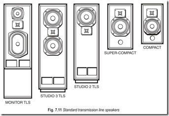
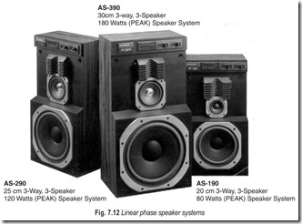
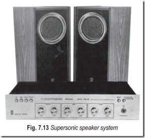
A disadvantage of the horn type is that when it fails to maintain its uniformity, it does so relatively suddenly. At the low-frequency end a horn has a cut-off frequency below which the horn quite abruptly fails to function as a horn. And at the high-frequency end any factors at the throat or in the horn development that cause deterioration there usually do so quite emphatically, with serious dips and peaks in the resulting response. So a multiway system, Figs. 7.11 and 7.12 using one or more horns (some systems combine cone units for some frequency ranges with horn speakers for others) must employ relatively sharp crossover filters so that very little energy is applied to the horn beyond its useful range of frequencies. Crossover filters should be complementary, or the overall response will not be correct. So making the filters sharp for the horns means that filters used for accompanying cone-type units must be equally sharp.
There are two disadvantages to high-slope crossovers: one is electrical and the other acoustical. Electrically, the sharper crossovers are more dependent for precisely correct response and on correct termination than are the simpler types. With the electronic crossover, of which few, if any, high-slope versions are currently available, this can be accurately built into the unit with the use of selected precision components. With the electrical crossover applied at the output, between a single power amplifier and multiple speaker units, the filters are terminated by speaker unit impedances, which are not simple resistances. So the simpler crossovers more easily achieve the responses they are intended to give.
Acoustically, the effect of phase response can be important. Tests have been made with subjective listening that suggest human hearing is not sensitive to phase differences so long as relative levels are not seriously modified (such as by cancellation). There is a fairly obvious reason for this: acoustic environment produces quite a variety of phase shifts, but the basic character of the sound is still interpreted, in spite of the environment, provided this is not severe enough to cause what may be recognised as colouration.
But the phase shifts thus considered are fairly small. If the changes are equivalent to sending the sound through a constricted, resonant pipe, it sounds like it. In a network that provides an ultimate roll-off of 24 dB/octave, the phase difference between the two outputs at every frequency (which is most important at crossover) is 360°, or a complete wave. Although the two waves are in phase with each other at that frequency, they are a whole period apart. And in any composite signal most of that 360° phase shift of a whole wave occurs between a fundamental and its harmonics. And if the system is more than two-way the effect of the various crossovers is additive. A sweep through the frequency range with a sinusoidal tone may give the impression that the response is extremely uniform–as it may well be—but the handling of this system applied to transient program signals may be another thing altogether.
These comments applied to multiway systems on a frequency division basis do not apply to systems that use a number of similar units to achieve the same or different objectives. For example, a group of units that would not handle the lower frequencies individually may do so easily when they are mounted on a common baffle board, or in the same cabinet, and driven in unison. Consequently, a group of units will handle a wider range of frequencies than each unit can individually. And the beam-type unit, which employs a row of units to make a line radiator, applies a combination of units to a different objective—the direction of sound where it is wanted and avoiding sending it where it is not wanted.
COMPONENT SYSTEMS ENHANCE YOUR HIGHS
In most cars, speakers mount at the bottom of the door. That’s fine for bass, but it doesn’t do much for the high frequencies.
Component speaker systems, with separate midrange/woofers and tweeters, let you put the bass down low and the highs where they belong—near your ears. You can mount the tweeters at the top of your door or on the dash, filling your car with a breathtaking stereo effect.
Component systems come with true crossover networks. The crossovers divide the sound between the tweeter and the mid/woofer, taking full advantage of the strengths of each component. Some models include tweeter level controls so you can fine tune the sound to suit you ear.
EXERCISES
Descriptive Questions
1. Differentiate between the acoustical characteristics of an indoor installation and an outdoor installation.
2. How will you achieve the best stereo illusion in different type rooms?
3. Explain the significance of a multiway speaker system.
4. The speaker size should be suited to room size. Explain.
Fill in the Blanks
1. Every indoor installation must live with the ………………………………… characteristics of the room where it will operate.
2. An outdoor installation does have to withstand………………………………… .
3. Outdoor speakers need the………………………………… efficiency economically feasible.
4. Horns have become almost universal for ………………………………… installations.
5. Horns provide natural weather………………………………… .
6. Horns are relatively………………………………… in efficiency.
7. Smaller horns come with the………………………………… unit as an integral part.
8. Larger horns have………………………………… drivers so that the power can be increased, where necessary, by fitting a more driving unit.
9. The directivity pattern depends more on the………………………………… design of the horn than on its shape, as observed externally.
10. Horn size relates to handling capacity and………………………………… frequency cutoff.
11. In any indoor installation every listener should hear first a sound at every component frequency, and then an appropriate amount of………………………………… of the same complex sound.
12. Speakers tend to generate sound waves ………………………………… with their size.
13. The technique in a live room is to utilise the ………………………………… , since you cannot easily get rid of them.
14. A resonable high-efficiency speaker might run about………………………………… % efficient.
15. A low-efficiency speaker is more likely to run about………………………………… % efficient.
ANSWERS
Fill in the Blanks
|
1. acoustic |
2. weather |
3. maximum |
|
4. outdoor 7. drive 10. power, low 13. reflections |
5. protection 8. removable, powerful 11. direct, reverberation 14. 25 |
6. high 9. internal 12. commensurate 15. 2 |
