AUDIO SYSTEMS
In the present scenario all the publicity and spare spending money was going on videos and computers. But now the video boom is levelling off, for the simple reason that most families which want and can afford a video recorder have one. However, there has always remained a hard core of audio enthusiasts who either like playing with- hi-fi equipment for the sake of it or like listening to music on hi-fi equipment for the better sound quality it offers.
The traditional aim of a hi-fi system is to reproduce recorded or broadcast sound with the highest possible fidelity to the original. Editing and all the high technology tricks available in a recording studio, let the artist create a sound on tape or disc that is wholly artificial, and more perfect than anyone could achieve in live performance. So hi-fi today is concerned with reproducing whatever the artist intended.
ANATOMY OF A HI-FI SYSTEM
The first essential is to have a stereo system. This creates a spread of sound from two loudspeakers, similar to that which we hear naturally with our ears. Virtually all sound reproduction systems are now stereo, but they are not necessarily hi-fi. There are plenty of very hi-fi stereo systems on sale, so do not confuse stereo with hi-fi.
There are two basic approaches to hi-fi. The system can be built up from several separate components, often from different manufacturers; or it can come as a single integrated system in a rack mount or music centre. Both approaches have their good and bad points.
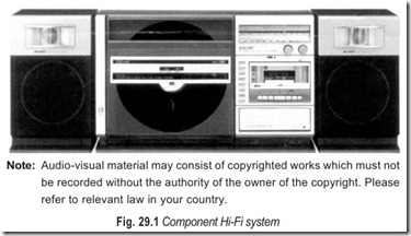
In the late 40’s and early 50’s, a group of inspired enthusiasts made it their mission to optimise each component of the console’s music reproduction system. Usually, this meant keeping those components separate, in order to render music with the highest fidelity to the original source. This was the beginning of what we now call component hi-fi, Fig. 29.1.
The advantage of separate components is their flexibility. Different numbers and combinations of components can be assembled into a system, according to the listener’s desire or needs. And as new technology arrives, only the component affected need be upgraded, not the entire system. Within each component type, there is a wide variety of features and performance levels so the listener can pick from whatever is available according to appetite or budget, returning to buy a state-of-art as needs and circumstances change.
Although component hi-fi has been around since the monaural days, the breadth and depth of choice still puzzles prospective buyers. A brief study of anatomy of a stereo system should put the options in clear focus.
— Microcomputer-controlled full auto system, from disc holder opening and play start to end.
— Two linear tracking arms for independent tracing of each side for beautiful music reproduction.
— Misoperation proof system for disc and cartridge stylus protection.
— Cassette deck with APSS (Auto Program Search System), metal tape capability and Dolby * NR.
*Dolby and “Double D” symbol are trademarks of Dolby Laboratories Licensing Corporation.
Basically a stereo system comprises three sections, signal source, signal processing and amplification. The first section extracts music from a storage medium, such as a disc or tape. The second section selects and boosts the weak source signal. The final section converts electrical signals into mechanical energy- sound waves through loudspeakers or headphones.
SOURCE UNITS
Sound is carried by various media. It’s the job of a source unit to extract the sound from its storage carrier and convert it into electrical impulses. Source units are the most numerous among audio components; most systems include more than one.
Compact Disc Players, Fig. 29.2, use a laser to extract sound that has been digitally encoded on a disc. Besides the standard 4¾ inch music CD, there are 3 inch minidiscs (dubbed CD-3s) and 4¾, 8 and 12 inch CDV-s that add still or motion video to the audio track. Some CD players (dubbed combiplayers) handle all disc types, including laser video; others are dedicated to sound reproduction only. Changer models house several CDs in a tray or magazine and can be programmed to play discs or individual cuts in any order.
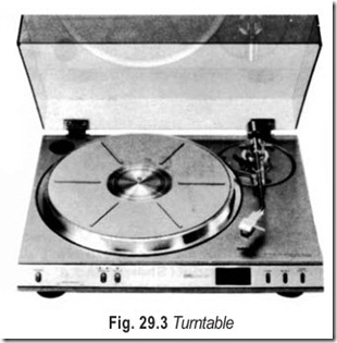
Turntables, Fig. 29.3, also called phonographs, are fitted with a phonocartridge stylus mounted on a tonearm. As the table spins at 33¾, 45 or 78 revolutions per minute, the stylus or needle extracts sound from the wiggly analog grooves of 7, 10, or 12 inch discs.
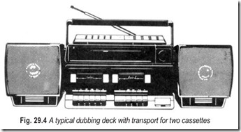
Tape deck’s sound-storage medium is magnetic tape housed either in small cassettes, eight-track cartridges or on larger, open reels (these last two formats are virtually extinct). Tape decks can record sound (on blank tapes) as well as play it back. The term tape player refers to a machine that does not have recording ability. Recording may be from live sources, through microphones, or from other source units in a system. Some cassette decks called editing or dubbing decks, have transports for two cassettes (see Fig. 29.4).
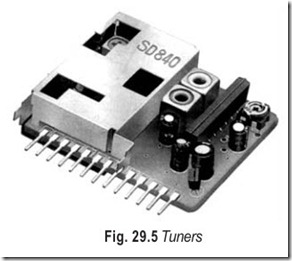
Tuners, Fig. 29.5, extract radio waves from the atmosphere. Some tuners receive only the high fidelity, usually stereo, f.m broadcasts. Most tuners also tune in the AM band, to accommodate listeners who lack a wide variety of FM fare. Tuners are available as separate components but can also be part of a popular hybrid components called the receiver, which houses signal processing and amplification circuitry in the same chassis.
Preamplifier, Fig. 29.6, also called a control amplifier, is the component to which all source units are connected—their port of entry into the audio system. It allows you to select the desired source and route the signal through the system. It also processes or manipulates the source signal with controls for bass and treble. Additionally, this component preamplifies the weak source signals before passing them on to the power amplifier.
Power amplifier, Fig. 29.7, is the business end of the system. The power amplifier boosts all the electrical signals, thereby providing the impetus that drives the loudspeakers to literally push air and generate sound waves.
Hi-fi speakers for average living rooms require at least 10 watts of audio output power from the loudspeaker, to handle most conditions. When several rooms, large rooms or outside areas, are to be supplied with the highest fidelity as much as 60 watts of power might be desirable in a home installation.
Audio control centresincluding preamplifiers, equalising networks, boost, droop, loudness, compensation, filtering and switching circuits are more elaborate and usually used instead of the plain preamplifier or a simple preamplifier equaliser.
From 50 to 100 dB of amplification of very low signals from pick-ups and other inputs according to the need, plus compensation and controls to obtain various emphasis, is provided by the preamplifier equaliser part of the system or by a separate hi-fi control centre unit.
Hi-fi systems are designed around either of these two types of amplifier arrangements, that is, the combination of preamplifiers, control, and power amplifier, all in one unit, or the control centre plus basic amplifier units separately. Circuit arrangement and components may be somewhat similar in both arrangements, but more flexibility and better results can be expected from separate units.
SIGNAL PROPAGATION
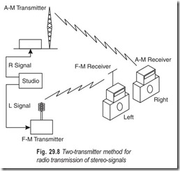
The first method used for stereo broadcasting and reception is illustrated in Fig. 29.8. Two complete transmitters were used, one sending out the left (L) stereo signal, the other the right (R) stereo- signal of the same program. All combinations of a.m broadcast, f.m broadcast, the television sound- channel transmission have been tried. Most popular were the FM/AM (one FM station and one AM station) and the FM/FM (two FM stations) methods.
The two-transmitter method of transmitting stereo was convenient because it utilised existing transmitting and receiving equipment with no circuit changes. However, it did have the following disadvantages:
(i)Two channels had to be used for each program, resulting in wasted spectrum space.
(ii) Differences in propagation characteristics of the waves radiated by the two transmitters led to variation in signal amplitude and quality within the separate channels. This was particularly true of FM/AM combinations, where the carrier frequencies are so widely separated.
(iii) In some cases, especially with FM/FM, the duplication of complex receiving equipment represented an excessive expense; ninety per cent of the programs were non-stereo, requiring only one receiver; but to receive stereo, two receivers were needed. Also a number of AM/FM tuners could not receive both bands simultaneously, and so they had to be supplemented with additional receiving equipment.
STEREO MULTIPLEX
The disadvantages of the two-station method made it imperative that a method of transmitting both signals on one carrier be devised. The result is the method called stereo-multiplex. Multiplex means a method of sending two or more messages simultaneously on one carrier or circuit. This is exactly what stereo multiplex does—it transmits both channels on the same FM carrier.
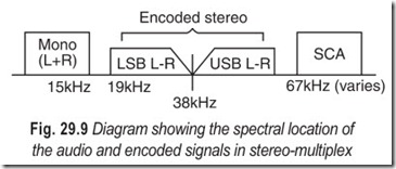
The standard FM broadcast system is based on an audio frequency response of approximately 0 to 15 kHz. There is nothing about the basic modulating systems to prevent extension of this audio-frequency range to 75 kHz (further extension would require more bandwidth than is currently allotted by FCC). Therefore, if at some point above the limit of human hearing (but still within the 75 kHz bandwidth) another signal is added, it will be amplified and detected by the regular receiver circuits. However, being above the range of hearing (supersonic) it will not interfere with the regular audio signal. Thus, the carrier is modulated by the regular audio signal plus the supersonic signal.
The supersonic modulation is known as the subcarrier (SCA in Fig. 29.9). It, in turn is modulated by another audio signal. As long as the bandwidth of the subcarrier is not allowed to extend downward into the range of regular carrier, no interference will occur. This complete modulated subcarrier signal is part of the composite signal which modulates the main carrier. One of the stereo signals is transmitted as modulation of the subcarrier. In receiving, two demodulating circuits are needed. First the main carrier is demodulated to get the first stereo signal and the modulated subcarrier. Then the modulated subcarrier is separated and demodulated to get the second stereo signal.
COMPATIBILITY
There will always be some listeners who don’t care about being equipped for stereo reception. Also, for portable use, and where cost is to be minimised, a conventional single-channel receiver is called for. For this reason, it is important that the stereo system be compatible. By compatible we mean that while stereo multiplex transmission is in progress a listener with a conventional receiver (one not equipped for stereo) should be able to receive the transmission as a full monophonic signal.
If one channel of the multiplex system is used for the L signal and the other for the R signal, compatibility is not provided. The owner of the conventional receiver hears only the modulation of the main carrier, which in this case would be just the L signal; the subcarrier frequency is above audibility, so neither the subcarrier nor its modulation is used. For a truly compatible system, the nonstereo listener should hear the combination of both L and R signals.
To meet this compatibility requirement, the main carrier can be modulated with a full monophonic signal (L + R), and the subcarrier channel can be modulated by the difference between the two signals (L–R).
The (L + R) modulation signal provides the nonstereo listener with his full monophonic reception; his receiver does not respond to and thus ignores the subcarrier.
For stereo reception, the L and R signals are recovered by demodulating the subcarrier signals and adding or subtracting the difference signal from the main carrier (L + R) signals.
Electrical addition of the signals can be accomplished simply by applying both signals across a common impedance. Subtraction can be accomplished by first inverting one of the signals (changing its phase by 180 degrees), then adding it to the other signal.
One point should be emphasised. Stereo reproduction is a part of high fidelity, not an “additional feature.” The impression is sometimes wrongly given that “hi-fi” and stereo are two separate stages of development of audio reproduction. This is a fallacy, unfortunately, sometimes encouraged by a statement that some equipment features “high fidelity and stereo.”
Stereo is a “fine point” in high fidelity; that is, if you do not have all the good qualities of high fidelity monophonic system to start with, other forms of distortion will prevent appreciation of the benefits of stereo effect. If the reproduction of your system is clean and clear of harmonic-intermodulation and transient distortion, it is likely that improvements in spatial sound effects through stereo will be appreciated.
EXERCISES
Descriptive Questions
1. What constitutes an audio system?
2. Discuss the relative merits and demerits of the two types of audio systems.
3. Which one would you prefer, a component system or an integrated system and why?
4. Describe the functions of the following
(a) source units (b) preamplifier
(c) audio control centre
5. Explain the two-tansmitter method of stereo broadcast. What are its disadvantages?
6. Discuss the significance of compatibility. How compatibility is achieved by stereo-multiplexing?
