Time delay contacts
The direction of the arrow indicates the switch operation, in which the contact action is delayed (time delay closing and opening contacts).
The contact in Fig. D-26 is open and will close after the timer is ener- gized and the time that is set passes.
The contact in Fig. D-27 is Normally Open. It will close when the timer is energized and will open after the time that is set passes.
The contact in Fig. D-28 is Normally Closed and will open after the timer is energized and the time that is set passes.
The contact in Fig. D-29 is Normally Closed. It will open when the timer is energized and will close after the time that is set passes.
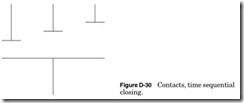
The contacts in Fig. D-30 are Normally Open and will close one at a time from left to right. Each contact will have a different time delay setting.
Pilot light designators
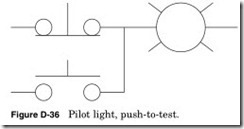
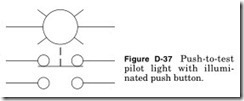
These are used to show the color or type of the pilot light.
| Designator | Color or Type |
| A | Amber |
| B | Blue |
| C | Clear |
| G | Green |
| NE | Neon |
| R | Red |
| W | White |
| Y | Yellow |
Shown in Fig. D-38:
Line 1 The control relay contacts CR1 and CR2 must be closed, and the button not pushed. Under these conditions the green pilot light will light.
Line 2 If the button is pressed, the contact will close and the pilot will light.
To indicate the type of meter or instrument (see Fig. D-39), place the letter(s) from the list below in the symbol. For other functions, look for a note in the notes section.
Meter designators
|
AM |
Ammeter |
VA |
Volt-ammeter |
|
AH |
Ampere-hour |
VAS |
Volt-ampere-reactive (VAR) meter |
|
mA |
Milliampere |
VARH |
VAR-hour meter |
|
μA PF |
Microampere Power factor |
W WH |
Wattmeter Watthour meter |
|
V |
Voltmeter |





![Figure D-38 Push-to-test pilot light, example._thumb[1] Figure D-38 Push-to-test pilot light, example._thumb[1]](http://machineryequipmentonline.com/electric-equipment/wp-content/uploads/2020/06/Figure-D-38-Push-to-test-pilot-light-example._thumb1_thumb.jpg)

