Electrical Control Symbols
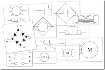
Symbols were developed to show the control logic on prints and dia- grams. They are most used on ladder diagrams and wiring diagrams. Standards for symbols for electrical components have been estab- lished by the National Electrical Manufacturers Association (NEMA). Standards Publication ICS 19-2002 sets forth the standards for the use of symbols. A copy can be obtained at www.nema.org. Not all manu- facturers, designers, and engineers use the standard symbols. Even when they use standard symbols, they sometimes use variations of the standard symbols. Of the 115 symbols that have been included here, some are not in the symbols standard but are commonly used on ladder diagrams.
Symbols are the language used on ladder diagrams and wiring dia- grams. In spite of the fact that not all symbols are standard, knowledge of the symbols in this chapter will give you the ability to read electrical prints and ladder diagrams.
Designators
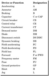
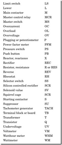
The following is a list of the standard designators used on electrical diagrams. Some of these can be used on an input or output.
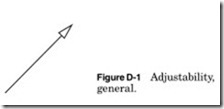
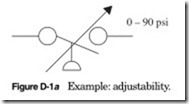
The symbol in Fig. D-1 is used to indicate that the device has an adjust- able setting; the range is usually indicated on the diagram. In Fig. D-1a I am showing a pressure switch with a range of 0 to 90 psi.
In the capacitor symbol (Fig. D-8), the polarity may or may not be shown. The straight line is the +, or positive, lead. The curved line is the –, or negative, line. The polarity of the capacitor is relative to + and – leads. They can both be positive or negative relative to ground.
The symbol in Fig. D-12 is used to show a magnetic coil. It can be a relay, a motor starter coil, or a contactor. It can be any device that has a magnetic coil. In Fig. D-12a CR is for control relay and the number 1 is for number 1 control relay.
Typical coil and contactor designators
| Function | Designation |
| Contactor | C |
| Latching | L |
| Main | M |
| Motor | Motor |
| Control relay | CR |
| Trip coil | TC |
| Unlatch coil |
ULC |
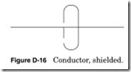
Conductor, shielded
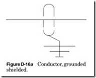
Shield may be shown grounded such as the one on the right. Only one side of a shield is grounded. This is to prevent a ground loop. Be careful to ground the correct end of the shield. If there are splices or junctions in the cable, make sure that the shield is spliced and does not contact ground. I like to use heat-shrink tubing to cover the shield at a junc- tion or splice. Also keep the unshielded part of the conductor as short as possible to prevent noise on the conductor.
General information on contacts
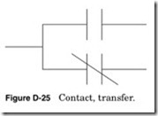
Contacts are shown on a diagram or wiring print in their inactive state. This means that their operator is the deenergized or nonoperated posi- tion. The activating device may be of any type. It could be manually operated such as a push button or a foot switch; it could be mechani- cal such as a pressure switch. It could be electrically activated as a relay. A note might be provided to explain the proper point at which the contact is operated, for instance, the point where the contact opens or closes as a function of level, pressure, flow, voltage, current, etc. A note should be provided if the contact is shown in the energized state or where confusion may result. Actuating devices may have many contacts; any of them can be open or closed. For example, a relay may have an unlimited number of Normally Open or Normally Closed contacts that change state when the relay is energized. A pressure switch usually has a Normally Open contact and a Normally Closed contact. Care should be taken to select the correct contact.
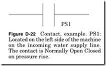
The Normally Open and Normally Closed contacts shown below can be used to indicate any device. The designer can use the Normally Open contact to show a pressure switch contact. The designer will usually use a standard designator to indicate this, for example, PS next to the contact to indicate that it is a pressure switch. The number indicates that it is a contact of pressure switch 1. Typically there will be a note on the print giving the location of the pressure switch.
