Direct-coupled, or Dc, amplifiers are used for high gain at low frequencies or for amplification of a direct- current signal. The DC amplifier is also used to eliminate frequency loss through a coupling network. Applica- tions of the DC amplifier include computers, measuring and test instruments, and industrial control equipment.
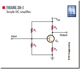
A simple DC amplifier is shown in Figure 38-1. The common-emitter amplifier is the one most frequently used. The circuit is shown with voltage-divider bias and emitter feedback. This type of circuit does not use a coupling capacitor. The input is applied directly to the base of the transistor. The output is taken from the collector.
The DC amplifier can provide both voltage and current gain. However, it is used primarily as a voltage amplifier. The voltage gain is uniform for both AC and DC signals.
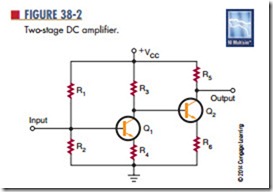
In most applications, one stage of amplification is not enough; two or more stages are required to obtain a higher gain. Two or more stages connected together are referred to as a multistage amplifier. Figure 38-2 shows a two-stage amplifier. The input signal is amplified by the first stage. The amplified signal is then applied to the base of the transistor in the second stage. The overall gain of the circuit is the product of the voltage gains of the two stages. For ex- ample, if both the first and second stages have a volt- age gain of 10, the overall gain of the circuit is 100.
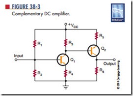
Figure 38-3 shows another type of two-stage DC amplifier in which both an NPN transistor and a PNP transistor are used. This type of circuit is called a complementary amplifier. The circuit functions the same way as the circuit shown in Figure 38-2. The difference is that the second-stage transistor is a PNP transistor, which is reversed so that the emitter and collector are biased properly.
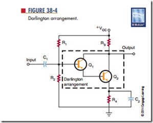
Figure 38-4 shows two transistors connected together to function as a single unit. This circuit arrangement is called a Darlington arrangement. Transistor Q1 is used to control the conduction of transistor Q2. The input signal applied to the base of transistor Q1 controls the base of transistor Q2. The Darlington arrangement may be a single package with three leads:
emitter (E), base (B), and collector (C). It is used as a simple DC amplifier but offers a very high voltage gain.
The main disadvantage of multistage amplifiers is their high thermal instability. In circuits requiring three or four stages of DC amplification, the final output stage may not amplify the original DC or AC signal, but one that has been greatly distorted. The same problem exists with the Darlington arrangement.
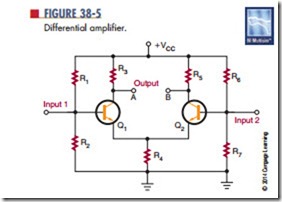
In applications where both high gain and tempera- ture stability are required, another type of amplifier is necessary. This type is called a differential ampli- fier (Figure 38-5). It is unique in that it has two sepa- rate inputs and can provide either one or two outputs. If a signal is applied to the input of transistor Q1, an amplified signal is produced between output A and ground as in an ordinary amplifier. However, a small signal is also developed across resistor R4 and is applied to the emitter of transistor Q2. Transistor Q2 functions as a common-base amplifier and amplifies the signal on its base. An amplified output signal is produced be- tween output B and ground. The output produced at B
is 180° out of phase with output A. This makes the differential amplifier much more versatile than a conventional amplifier.
The differential amplifier is generally not used to obtain an output between output and ground. The output signal is usually obtained between output A and output B. Because the two outputs are 180° out of phase, a substantial output voltage is developed between the two points. The input signal can be applied to either input.
The differential amplifier has a high degree of temperature stability because transistors Q1 and Q2 are mounted close together and therefore are equally affected by temperature changes. Also, the collector currents of transistors Q1 and Q2 tend to increase and decrease by the same amount so that the output volt- age remains constant.
The differential amplifier is used extensively in integrated circuits and electronic equipment in general. It is used to amplify and/or compare the amplitudes of both DC and AC signals. It is possible to connect one or more differential amplifiers together to obtain a higher overall gain. In some cases, the differential amplifier is used as a first stage, with conventional amplifiers used in succeeding circuits. Because of their versatility and temperature stability, differential amplifiers are the most important type of direct-coupled amplifier.
Questions
1. When are direct-coupled amplifiers used in a circuit?
2. What kind of amplifiers are direct-coupled amplifiers primarily used for?
3. Draw schematic diagrams of the following circuits:
a. Complementary amplifier
b. Darlington arrangement
c. Differential amplifier
4. How does a differential amplifier differ from a conventional amplifier?
Where are differential amplifiers primarily used?
