Audio Amplifiers
Audio amplifiers amplify AC signals in the frequency range of approximately 20 to 20,000 hertz. They may amplify the whole audio range or only a small portion of it.
Audio amplifiers are divided into two categories: voltage amplifiers and power amplifiers. Volt- age amplifiers are primarily used to produce a high voltage gain. Power amplifiers are used to deliver a large amount of power to a load. For example, a volt- age amplifier is typically used to increase the voltage level of a signal sufficiently to drive a power ampli- fier. The power amplifier then supplies a high output to drive a load such as a loudspeaker or other high- power device. Typically, voltage amplifiers are biased to operate as class A amplifiers, and power amplifiers are biased to operate as class B amplifiers.
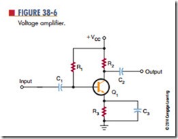
Figure 38-6 shows a simple voltage amplifier. The circuit shown is a common-emitter circuit. It is biased to operate as a class A amplifier to provide a minimum amount of distortion. The amplifier can provide a substantial voltage gain over a wide frequency range. Because of the coupling capacitors, the circuit cannot amplify a DC signal.
Two or more voltage amplifiers can be connected together to provide higher amplification. The stages may be RC coupled or transformer coupled;
transformer coupling is more efficient. The trans- former is used to match the input and output imped- ance of the two stages. This keeps the second stage from loading down the first stage. loading down is the condition when a device creates too large a load and severely affects the output by drawing too much current. The transformer used to link the two stages together is called an interstage transformer.
Once a sufficient voltage level is available, a power amplifier is used to drive the load. Power amplifiers are designed to drive specific loads and are rated in watts. Typically a load may vary from 4 to 16 ohms.
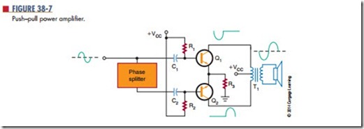
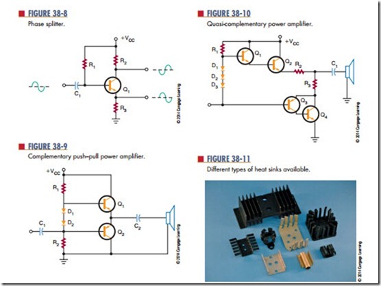
Figure 38-7 shows a two-transistor power amplifier circuit, called a push–pull amplifier. The top half of the circuit is a mirror image of the bottom half. Each half is a single transistor amplifier. The output volt- age is developed across the primary of the transformer during alternate half-cycles of the input signal. Both transistors are biased either class AB or class B. The input to a push–pull amplifier requires complementary signals. That is, one signal must be inverted com- pared to the other. However, both signals must have the same amplitude and the same frequency. The cir- cuit that produces the complementary signal is called a phase splitter. A single-transistor phase splitter is shown in Figure 38-8. The complementary outputs are taken from the collector and the emitter of the transistor. The phase splitter is operated as a class A amplifier to provide minimum distortion. The coupling capacitors are necessary to offset the differences between the A push–pull amplifier that does not require a phase splitter is called a complementary push– pull amplifier. It uses an NPN transistor and a PNP transistor to accomplish the push–pull action (Figure 38-9). The two transistors are connected in series with their emitters together. When each transistor is properly biased, there is 0.7 volt between the
base and emitter or 1.4 volts between the two bases. The two diodes help to keep the 1.4-volt difference constant. The output is taken from between the two emitters through a coupling capacitor.
For amplifiers greater than 10 watts, it is difficult and expensive to match NPN and PNP transistors to ensure that they have the same characteristics. Figure 38-10 shows a circuit that uses two NPN transistors for the output-power transistors. The power transistors are driven by lower-power NPN and PNP transistors, and the upper set of transistors is connected in a Darlington configuration. The lower set of transistors uses a PNP transistor and an NPN transistor. Operating as a single unit, they respond like a PNP transistor. This type of amplifier is called a quasi– complementary amplifier. It operates like a com- plementary amplifier but does not require high-power complementary output transistors.
Because of the large amounts of power generated by power amplifiers, some components get hot. To assist in the removal of this heat buildup, a heat sink is used. A heat sink is a device that provides a large area from which the heat can radiate. Figure 38-11 shows different types of heat sinks used with transistors.
Questions
1. For what frequency range are audio amplifiers used?
2. What are the two types of audio amplifiers?
3. What is an interstage transformer?
4. Draw schematic diagrams of the following:
a. Push–pull amplifier
b. Complementary push–pull amplifier
c. Quasi-complementary amplifier
5. How can excess heat generated by an amplifier be removed?


