Ampere turns is a term in a formula used in designing a pole. The strength of a pole is governed by the number of turns in its coil and the number of amperes flowing in them.
The shunt field of a DC machine has a large number of turns and a small number of amperes. Fewer turns and more amperes will do the same job but would be much more expensive to operate.
The series field in the DC machine is in a high-ampere circuit. It has very few turns, but its magnetic strength can be comparable to that of the shunt field.
The Magnetic Circuit
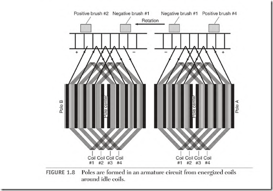
The circuitry of an electric motor sometimes seems very complicated. The armature of a DC motor is a good example. When the energized coils of the
armature are isolated and displayed (Fig. 1.8), they take the same shape as the electromagnet shown in Fig. 1.4—a coil of wire around a piece of iron. Magnetic circuits in most motors are a variation of the basic electromagnet in Fig. 1.4.
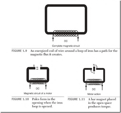
A complete magnetic circuit (using a coil of wire as its power source) is shown in Fig. 1.9. The amount of current through the coil controls the number of lines of force (flux) in the magnetic loop.
When the magnetic loop is opened (Fig. 1.10), north and south poles are established on the ends of the iron. The direction of current flow through the coil determines the polarity at the ends of the iron. In a motor or generator, these poles are stationary and are part of the stator. The outer shell of the stator carries the lines of force from pole to pole.
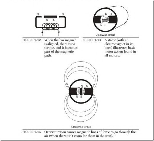
If a bar magnet is placed in the opening (Fig. 1.11), the magnetic forces will cause torque. The bar magnet will try to align with the poles of the stator as shown in Fig. 1.12. (Unlike poles attract, and like poles repel.)
Positive brush #2 Negative brush #1 Negative brush #1 Positive brush #4
Figure 1.13 shows the basic magnetic action of all electric motors. The poles of the bar magnet represent the magnetism developed in the armature of a motor.
Magnetic Saturation
The iron of a magnetic circuit has a limited capacity to carry lines of force. When this capacity is reached, it is called magnetic saturation or fully magnetized. When the iron’s capacity is exceeded, it is called oversaturation. Figure 1.14 illustrates what happens to some of the lines of force when oversaturation occurs.
Magnetic Balance
When electric motors and generators are designed, great care is taken to magnetically balance all the poles. The poles are placed an equal distance from each other around the stator. Each pole has the same number of turns of wire and produces the same amount of magnetism. The shell of the stator is the outer part of the magnetic circuit. The iron of the armature completes the inner part of the magnetic circuit.
Magnetic unbalance will cause bearing problems, loss of power, and internal heating in the armature.
Neutral Position in the Stator
The neutral spot is located an equal distance between the north and south poles. Magnetic neutral is 90 electrical degrees from each adjacent pole center. Interpoles (explained later in the chapter) are located in the stator’s neutral position (Fig. 1.15). The correct brush setting will align the pole centers of the armature with the stator’s neutral position on all DC machines.


