Properties of ER Fluid in Flow Mode
The data presented in this section is from tests carried out on a valve of dimensions of length 60 mm and diameter of 60 mm with a gap of 0.5 mm. The flow rates of 3, 9, and 15 l/min were used and the pressure drop across the valve was measured and simultaneously the current were measured for step input of high voltage. Similarly, the sinusoidal voltage of amplitude 50 V superimposed on a base voltage of various magnitudes at different frequency was applied and the pressure drop and current were recorded on a high speed computer. It is clear that the data gathered from the above tests is huge and only the important phenomena which can be used for design purpose is presented here.
One of the important properties of ER valve is the voltage and current relation- ship in the steady state values. This is shown in Fig. 8.6. It can be seen that the voltage and current relationships are nonlinear. In some papers, it is stated that there is nonlinear relationship and a quadratic relationship in the form of V = RI2 is proposed. The author has proposed that the linear relationship of V = RI exists and the nonlinearity is due to the change in fluid resistance at different applied voltage.
The small variation of the flow rate on the resistance is negligible. It is clear that the variation of current on flow rate is very small and may be ignored. This is useful in design of power supply for fluid in flow mode.
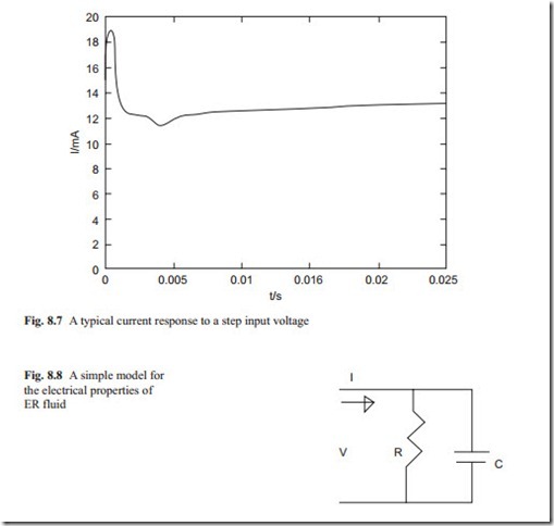
To design a power supply, the dynamic relationship between the current and volt- age must be known. This can be found from the step input of voltage and observing the current. This is shown in Fig. 8.7. It can be seen that as the voltage is applied, the current rises rapidly to a large value and then it reduces to its steady state values. The sinusoidal input superimposed to a constant base value of voltage relationship (not shown here) shows that the current leads the voltage.
This indicates that there is a charging phenomenon and this point can also be predicted from the step input voltage response. Therefore, an adequate electrical model would be in the form of a capacitance parallel to a resistance.
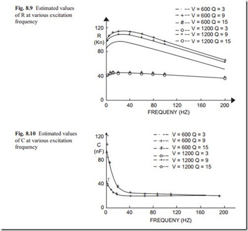
This is shown in Fig. 8.8. It was stated that above the capacitance and resistance are variable with respect to the applied voltage frequency. An identification
technique was used to identify the values of R and C from sinusoidal input voltage superimposed on a base voltage response. The values of R and C identified are presented in Figs. 8.9 and 8.10.
The data presented in Figs. 8.9 and 8.10 are at two base voltages of 800 and 1200 V respectively and at different flow rates. It can be seen that the values of R and C depend on the base voltage and the excitation frequency. As the excitation frequency increases, the resistance initially increases and then it reduces and it seems that at high frequency they reach a steady state values. The resistance is smaller at higher voltage than low voltage. This was observed at steady state relationships between voltage and current.
The capacitance initially is very large but it reduces rapidly reaching a steady state at high frequency. Again the capacitance does not depend on the flow rate and it only seems that its value is smaller at high applied voltage. Figures 8.9 and 8.10 are useful for the power supply design. The power supply must have the capacity of rapid current which rises about ten times than the steady state current. Alternatively it must be able to limit the maximum current so to avoid excessive heat generation
in the electronics. For fast response requirement applications, the power supply must be able to generate large voltage with little time delay.
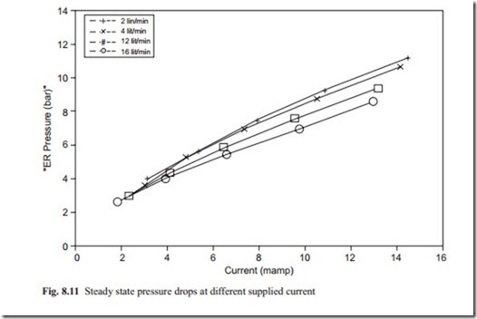
Another important property of ER fluid in flow mode is the steady state pressure drop across the valve at various current. This is shown in Fig. 8.11.
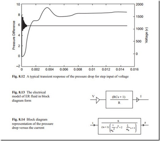
The above diagram shows that there is approximately a linear relationship be- tween the current and the pressure drop across the valve at steady state. The flow rate has little influence on these phenomena. It would be interesting to investigate the transient behavior when a current is applied across the valve. This is shown in Fig. 8.12.
It can be seen that there are two distinct phenomena in the transient response. One is a first order lag type which increases exponentially and the other one is the response of a second order transfer function. When the transfer functions cascaded together produces this kind of response.
The above analysis shows that there is a transfer function between the current and input voltage and there is another transfer function between the pressure drop and the current. The transfer function between pressure drop and current can be obtained with assumption that the current response is much faster than the pressure. This approximation can be made because the current response is very fast and in Fig. 8.12, it can be assumed that it is pressure response to the applied current.
From Fig. 8.8, the transfer function between current and voltage can be obtained
Equation (8.1) shows that there is a lead network in the transfer function. At steady state when s = 0, the current reaches a steady state value of V/R. Initially when the voltage is applied current rises rapidly and then decays to the steady state value. Equation (8.1) can be written in block diagram form as shown in Fig. 8.13.
The values of R and C are variables and their values depend on the operating point. The pressure drop and current relationship by inspection of Fig. 8.12 can be approximated as
The time constant, natural frequency, and damping ratio can be obtained directly from Fig. 8.12 by using their unique properties discussed in Chaps. 1 and 3. Al- ternatively identification technique may be used to obtain a more accurate model. Equation (8.2) may be shown in block diagram form as shown in Fig. 8.14.
Properties of ER Fluid in Shear Mode
Figures 8.13 and 8.14 may be represented by a single block. From tests carried out on the simple valve shows that the pressure response does not depend on the flow rate. Having obtained a mathematical model, various control strategies such as proportional or proportional and integrator may be used. The current feedback may be used to dampen the dynamic response. The exercise is left to the reader to investigate or it could be set as a final year project. The identification procedure of obtaining all the parameters can be set as a master year project. This exercise can be repeated for various flow rates and voltages and gaps.
Another research area is to study the valve properties over different valve length and diameter although from above analysis they can be predicted.
