Proximity detectors
The measurement of mass or volume is often much less important than the sensing of the presence of material, known as proximity detection. There
are several forms of proximity detectors, all of which are industrially important and which feature to a considerable extent in all automated equipment. The main uses for proximity detectors range from the simple counting of objects by detecting their presence, to checking for faulty assembly and ensuring that objects are correctly positioned for a subsequent operation.
The simplest form of proximity detection is touch detection, using a microswitch, often connected to a probe, to sense the position of an object. This method has the considerable advantage that it is not affected by the type of material (it is not confined to metal objects, for example), but it does have the drawback of being useful only for objects whose mass is enough to operate the mechanism, and for objects which will not be damaged by being touched.
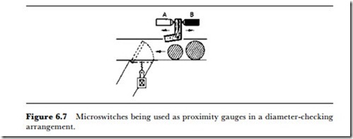
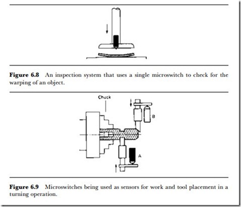
Figure 6.7 shows a typical application in an automatic sizing gauge for rejecting undersize (or oversize) objects. The lever arm normally touches microswitch A, and will be lifted by each object passing it. If an object is too small to move the arm away from microswitch A, it is too small and can be rejected. If an object is too large, it will press the arm against microswitch B, also actuating the trapdoor rejection mechanism. This very simple example is widely used for the size-grading of objects, and the principle of using two microswitches for maximum and minimum tolerance measurement is one that is found in a large number of applica- tions. The inspection system illustrated in Figure 6.8 depends on the use of a single microswitch to detect warping of a surface – obviously the principle could be adapted to check for convex warping as well as for the concave warping shown here.
Microswitches used in this way are almost universally of the electrical changeover variety, so that either the opening or the closing of a micro- switch can be sensed, as in Figure 6.7. Most microswitches allow a maximum travel of the actuating pin which is large in comparison to the range required for detection. In some mechanisms it is necessary to mount the microswitches themselves on a sprung holder to ensure that a grossly oversize object cannot cause damage to the switch itself.
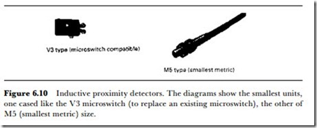
By far the most common application for microswitch proximity sensing, however, is in tool or workpiece placement on automatic turning, drilling, punching and press equipment. Figure 6.9 shows a typical application in which microswitch A is used to sense that the work is correctly positioned with reference to a flange, and microswitch B is used to position the cutting tool for a chamfer. It is particularly in this type of application that the microswitches must be protected against excessive movement, and since considerable damage can be caused by failure of a microswitch or its associated circuitry, such mechanisms should always use a back-up set of micro- switches that will cut off power in the event of an over-travel of either tool or work. Safety considerations will also require microswitches to be used to detect any movement of safety guards or visors.
For some applications, mercury tilt-switches can be used rather than microswitches. Although, as the name suggests, these switches are used to sense an alteration in angular position rather than linear motion, many of the movements that are sensed by microswitches involve the rotation of an arm and are potentially applicable to tilt-switches. Unlike the microswitch, in which spring-loaded contacts are used, there is no switch-bounce effect in a tilt-switch. For some applications in which the number of contacts are digitally counted, the tilt-switch can be preferred, although most counter circuits incorporate anti-bounce circuitry (in which the counter is disabled for a short time after receiving an input so that multiple inputs due to switch-bounce are not counted).
INDUCTIVE PROXIMITY DETECTORS
Inductive proximity detectors operate on the principle that the inductance of a coil is considerably changed in the presence of a metal core. The coil can be part of a bridge circuit or the inductor in a tuned circuit. The presence of metal close to the coil will thus cause a bridge output off- balance condition or a change in the tuned frequency that can be sensed. The change is normally used to operate a switching circuit by way of a tran- sistor or a Triac, so that the output is suitable for controlling a load. The predominant switch action is normally open (NO), although a few types are available in a normally closed (NC) action. The use of changeover (CO) action is unusual.
The overwhelming advantage of inductive proximity switches is that no part of the switch need touch the object being sensed. Their disadvantage is that they sense metallic objects only, and with a sensitivity that depends on the type of metal used. The sensitivity is quoted in terms of average sensing distance for an object of mild steel and, depending on the type of detector, this distance is of the order of 0.8-2 mm for mild steel. Other metals lower the sensitivity, to 70% for stainless steel, 40% for brass, 35% for solid aluminium, and 30% for copper. Most inductive proximity sensors are DC operated, with the choice of current source or current sink action. A current-source type will pass current into a load; a current-sink type will accept (to ground) current from a load. Current ratings are in the 100-200 mA region at DC voltage levels of 5-30 V. A few types allow AC operation, some at mains 240 V level, with current ratings up to 500 mA, allowing light loads to be driven directly.
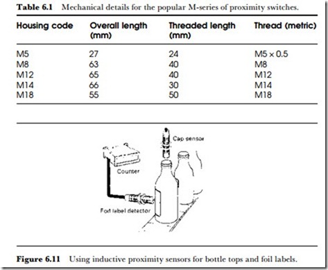
The housings for inductive proximity switches present a considerable variety, of which two of the smallest styles are illustrated in Figure 6.10.
Table 6.1 shows the dimensions for some typical units in the metric threaded type. Several of the physically larger types incorporate a LED telltale which will light when the target is sensed. This feature makes setting up much easier, since the load can be disconnected during this time while still allowing the sensor to function.
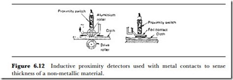
The applications for inductive proximity switches are more extensive than might be thought of in a device that is primarily a metal sensor. Figure 6.11, for example, shows a counter and sensor for bottles which checks for metal caps and foil labels being correctly fitted and positioned. The use of light metal foils as contacts to a non-metal can make it possible to use inductive sensors in a range of applications for which they would at first sight be rejected, such as the cloth thickness sensors illustrated in Figure 6.12. The comparatively small distance over which a metal object can be sensed can be turned to advantage in using these detectors for sensing incorrect positioning of metal objects, even to the extent of sensing which way round staples have been packed in a cardboard container.
Inductive proximity detectors are also particularly useful in machine tool applications such as injection-moulding presses where they can be used to sense the closure of a mould, and in all of the types of application for which microswitches are also used. Inductive sensors are, however, considerably
more expensive than microswitches, and their use is more likely to be confined to where their advantages are unique in not requiring to make contact with the object that is to be sensed. Other particularly useful features of inductive sensors are the high rates of repetition, ranging from 200 Hz to 2 kHz for the small DC types, to 25 Hz for the AC types, and the working temperature range of, typically, -25oC to +85oC.
CAPACITIVE PROXIMITY SENSORS
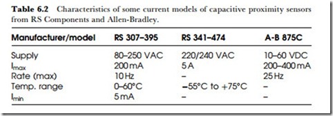
Capacitive sensing proximity detectors make use of the stray capacitance that exists between a metal plate and ground, a quantity that can be altered by the presence of non-conducting material as well as by either grounded or isolated conducting material. As before, either a bridge or a resonant circuit detection method can be used, although the resonant system is more common because the stray capacitances are small. A notable feature of capacitive proximity detectors is that the detectable range is much higher than it is for the inductive type. Both AC- and DC- operated detectors are available, and Table 6.2 shows some current versions of these detectors.
In Table 6.3, the ranges are approximate because much depends on the size and shape of the object being sensed as well as on the material. Powders and liquids can be sensed in addition to solids, but any average figure of distance would be misleading for such applications. Grounded
metals can be detected at a fairly large range – the figures quoted in the table are for copper (Cu) or aluminium (Al). Repetition rates are in general lower than for the inductive type of sensors. The 200/240 V AC type shown in the table also incorporates a delay feature, hence the omission of any rate or repetition figure. The delay can be varied from 2 s to 10 min to allow for other processes (such as starting a pump or emptying a hopper).
ULTRASONIC PROXIMITY DETECTORS
The ultrasonic type of sensor can make use of diffuse-scan mode (using the same transducer as transmitter and receiver, and detecting a reflected signal) or through-scan mode (using two transducers and detecting when the signal is interrupted). Through-scan mode allows for a much greater range of action, but the diffuse-scan mode is more common for many applications.
The frequency of ultrasound is critical, because a substantial number of industrial machines emit ultrasound in the near-sonic range of 20-50 kHz and sometimes higher, so that the use of such frequencies for proximity sensing is liable to be considerably affected. For that reason, a frequency of 215 kHz is favoured for proximity detection. The output from the transducer is modulated, using frequencies in the range 30-360 Hz, and this modulation acts as another safeguard against interference. The modulation frequency also affects the minimum sensing distance in diffuse-scan mode, since an object cannot be sensed if the transducer has not switched to receiving by the time the echo returns.
Typical ranges for the diffuse-mode types are 100-800 mm for modulation rates of 20-8 Hz; ranges down to 10 mm can be obtained when a higher modulation frequency is used. When through-mode is in use, the ranges can be longer, though 1 m is a typical maximum. When more than one diffuse-mode transducer is being used, care has to be taken so that there is no possibility of one transducer receiving the beam from the other and so working in through-mode.
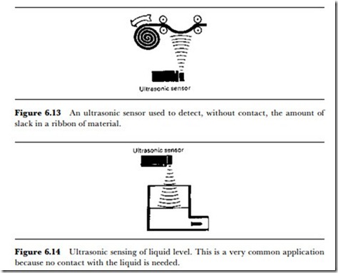
Ultrasonic proximity detectors are particularly useful in applications that are not well suited to inductive or capacitive types. Figure 6.13 illustrates
an application to maintaining a slack portion of a material that is being wound, preventing stretching due to tensioning of the material, or jamming caused by an excessively slack section. Figure 6.14 shows a liquid level sensor in which the ultrasonic beam is reflected from the liquid surface, detecting (in this example) when the container has been emptied and to what extent it is later filled again.
The use of ultrasonic detection requires some care in the selection, positioning and use of the sensors. The maximum sensing distances that are quoted in data sheets refer to targets with a smooth reflecting surface of at least 30 X 30 mm, arranged orthogonally to the beam (surface plane at 90o to the line of the beam), at 250oC ambient temperature and 60% humidity with negligible air movement. Since the ultrasonic beam is a sound wave in air, it is affected by air movement (which will alter the beam directions of both transmitted and reflected beams) and by the air humidity (which affects the speed of ultrasound). The effect of air temperature is that the speed of ultrasound in air increases by 0.18% for each oC change of air temperature. This is often compensated for within the transducer by altering the clock speed for the time counter as air temperature changes.
A target area smaller than the 30 X 30 mm that is assumed, will reduce the maximum range – as a rough guide, a reflecting surface of 10 X 10 mm will halve the maximum range figure. A target which consists of a smooth flat surface will be undetectable if the surface is angled so as to reflect the return beam away from the transducer – remember that the angle through which the beam is deflected is twice as great as the angle through which the target surface is turned. This effect is more critical at the longer ranges at which the tolerance can be as low as ±2o, but is not so significant at closer ranges. Nevertheless, ultrasonic proximity detection is much less tolerant of target orientation than other sensing methods.
The types of material that can be detected exclude only a few sound- absorbing substances, such as cotton-wool and rubber foams, but many textile surfaces provide only very weak echoes. In general, very porous materials are not suitable for ultrasonic detection.
PHOTO BEAM METHODS
Optical beam proximity detectors can use through-scan, with one source and one receiver aimed at each other, retrorefiective-scan, with one combined source and receiver used with a mirror, and di.ffuse-scan, making use of a combined source and receiver with light reflected from the object itself. The prices of the respective units are not widely different, so that through- scan methods are very often used where retroreflective methods might be equally applicable. The light source is usually an LED working in either the visible red or the (invisible) infrared range. The use of visible red light makes setting-up easier, particularly over long distances, but the infrared type is less likely to suffer from interference from other light sources.
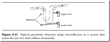
The range of optical proximity units can be large, up to 15 m for a through-scan type, about half for retroflective use, and typically up to 700 mm for diffuse reflection. The through-scan and retroreflective types depend on the object breaking the beam, but the diffuse-reflection type can be used to sense the approach of an object along the beam as well as cutting the beam. Figure 6.15 illustrates an application of a pair of retrore- flective units in maintaining a slack loop in a strip feed, a very common application. The advantage of the optical system is that large loops can be accommodated, much larger than can be sensed by ultrasonic systems, for
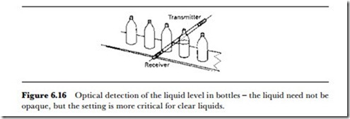
example, making this system applicable to paper, plastic sheet, rubber and other industries. Another problem that is particularly suited to an optical solution is level detection in bottles on a line (Figure 6.16).
Whether visible red light or infrared is used, sensors make use of pulse- modulated signals and polarizing filters to ensure that neither stray light nor multiple reflections cause problems of false triggering. Optical units are available with relay or solid-state switching, DC or AC operation, with or without time-delays, and usually with built-in LED signals so that the sensors can be checked for alignment without the need to actuate other units in an automated system.
Photosensing units can also be used along with fibre optics where the area of use is to be closely confined. The use of 0.5 mm diameter fibres, for example, can allow optical sensing to be used in spaces which are inaccessible to the normal type of unit, with the advantage that the path of the fibre can be bent with negligible loss of light transmission. For building into new equipment, combined LED and photosensor units can be obtained at very low prices, allowing the designer to use whatever amplifying and relay system is preferred.
REED SWITCH/MAGNET AND HALL-EFFECT UNITS
For specialized applications, the use of a reed switch and magnet is a robust and simple proximity detector. The principle is simple – the reed switch is closed (or opened) when the magnet is within range, usually a few millimetres distance, and the reed switches over when the magnet is withdrawn. The system is confined to detecting changes on objects that always mate together, such as doors and doorways, and is widely used in safety interlock- ing and burglar alarm systems. The reed-switch contacts can carry an acceptable load current, so that no intermediate relay is required for most of the applications of the system. For details of reed-switch mechanisms, see Chapter 12.
Hall-effect units are also magnetically operated, but the magnetic field strength required for a Hall-effect detector can be very low, as low as that of the Earth if needed. Hall-effect proximity detectors are therefore capable of sensing magnets at greater distances than can be used by reed-switch systems and, in addition, because the Hall-effect sensor can detect small changes in magnetic field it can sense interference with the normal magnetic field of the Earth, such as might be caused by steel objects. The switching is bounce free, unlike that of the reed switch, and in some applica- tions the Hall-effect sensor can be used like an optical unit to detect the passing of a ferrous object between a magnet and the sensor. This has the advantage that counting can be carried out in conditions (such as in black liquids) which would be impossible for an optical beam.
DOPPLER DETECTORS
The most exotic of proximity detectors (for moving objects only) is the microwave radar type using the Doppler effect. This operates in X-band in the 10.675-10.7 GHz region, and requires a licence under the Wireless Telegraphy Act of 1949 – the licence is for 5 years and is obtained from a DTI branch in Cardiff. An application form is supplied with each Doppler unit bought from RS Components.
Although the technology may seem exotic, the price of a radar proximity unit is surprisingly low – little more than that of a PIR unit. The unit contains a Gunn diode oscillator with 10 mW output located in a launching horn, and a receiving horn containing a mixer diode. A section of waveguide, between the horns, supplies some of the oscillator output to the mixer for frequency mixing, and the mixed output, a low-frequency signal generated when any object in the field of view moves, is amplified in a separate unit.
The detection ability depends on the size of the target, and a moving human body can be detected reliably at ranges of typically 1-15 m. A moving human generates a Doppler signal whose frequency is centred around 50 Hz, and amplifiers for a Doppler system have their maximum sensitivity at this frequency. This imposes two restrictions on the use of the system. One is that fluorescent lighting in the target area should be switched off when the system is operating. The ionized gas in a fluorescent tube acts as a reflector while the tube is conducting but not when the tube is in its non-conducting state, so that a strong radar return at 100 Hz will be obtained from any fluorescent source. This restriction is not as important as it might seem, because radar detection methods are particu- larly suited to dark spaces – optical methods can be used in well-lit spaces. The other restriction is that the abnormally high sensitivity of the amplifier to 50 Hz requires 12 V battery operation rather than a mains supply. The problem is one of hum pick-up from mains wiring rather than from inadequate smoothing. False alarms can be caused by vibration which shakes the alarm module, movement of objects like curtains, doors, banners, etc., and air turbulence in plastic water pipes.
