Circuit Symbols
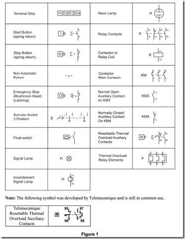
The following are the circuit symbols commonly used in motor related schematic diagrams.
Panel Wiring Techniques
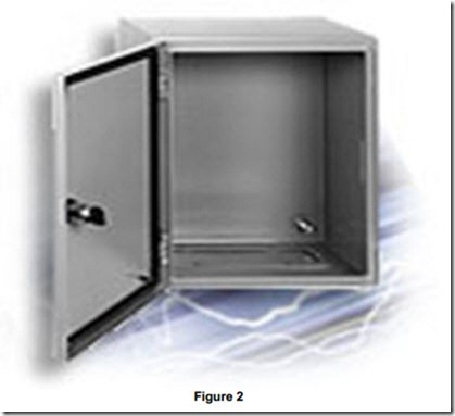
Electrical control panels are available in all shapes and sizes to suit the particular requirements of the situation. These panels may be small as shown in Figure 2, or very large as required to house the necessary components. They must of course provide the required level of protection from the prevailing conditions in the location.
The control equipment may be mounted in the panel in a number of ways as follows:
Drilled or Tapped Mounting Plates
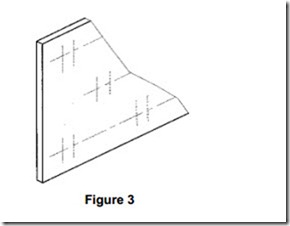
Figure 3 illustrates a section of a drilled and tapped mounting plate. This mounting method can be costly unless large volume production is involved.
Slatted Mounting Screens
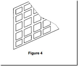
Figure 4 illustrates a section of slatted mounting screen. This mounting method suits any type of equipment and is quick and easy to assemble.
Mounting Rails
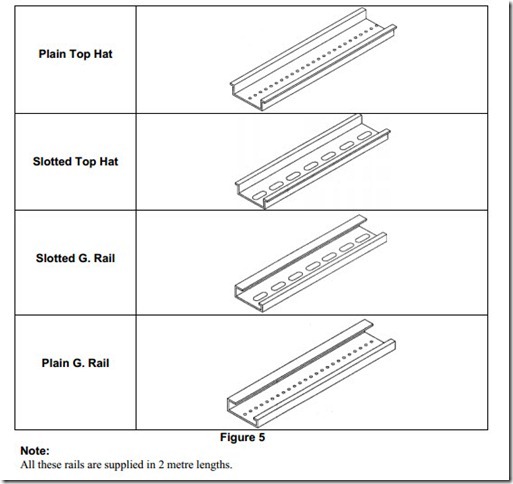
Mounting rails are made up of cold rolled steel. After being rolled, they are treated to prevent corrosion. Mounting rails are used for snap-on mounting of electrical equipment. A selection of mounting rails is illustrated in Figure 5.
Panel Wiring Cable
This is an insulated flexible cable without a sheath. It is generally run in slotted trunking with a clip on lid, inside a control panel. Panel wire is available as follows:
Note: For CENELEC Cable coding system see ETCI Rules
The following cable colours are available:
Brown; blue; green/yellow; black; green; grey; orange; pink; red; yellow; violet and white.
Crimp Connectors
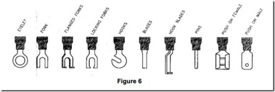
A wide range of crimp connectors is readily available in both insulated and non-insulated types to suit any particular electrical application.
Figure 6 shows some of the crimp connectors in common use.
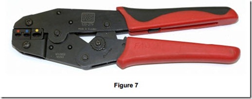
Figure 7 shows a typical ratchet type crimping tool used for the termination of insulated crimp connectors to cables. It is colour coded to indicate the size of crimp connector and matching conductor. Red for 1.52 mm, blue for 2.52 mm and yellow for 42 mm and 62 mm. Some of these tools require that the connector be inserted the correct way round. If this is not done, a poor joint between cable and connector will be the result.
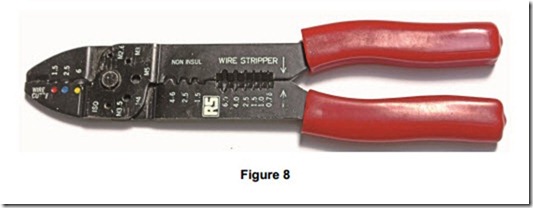
Figure 8 shows a multipurpose tool. It features a cable cutter, sections for insulated and non- insulated crimp connectors as in figure 7. It has a cutter for the common size machine thread brass screws ( 2.6 mm to 5 mm ) which allows screws to be cut clean avoiding damage to the start of the thread. It also has a wire stripper for cable sizes 0.752. to 62. The jaws must be fully closed to ensure correct pressure is applied to connector etc.
Panel Trunking
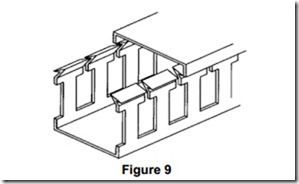
Figure 9 illustrates a section of PVC slotted trunking used inside electrical control panels to accommodate cable runs. It is available in 2 metre lengths and various widths and heights – for example it is available in sizes from 15mm wide x 17mm high to 100mm x 100mm. Divider walls can be inserted for segregated compartments. The lid is simply clipped on in place. Sections can be removed from the sides to allow cables enter or exit. The wiring can easily be altered or modified after initial installation. It is fast to install.
Cable Lacing
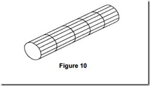
Figure 10 illustrates a section of cable loom formed using the cable lacing method. Cable lacing allows looms to be made up prior to assembly. This wiring method is very fast and cheap for high volume work. Cable ties or spiral cable wrapping may also be used.
Wiring of Enclosure Doors
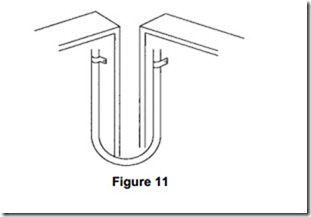
Figure 11 illustrates a typical method of wiring an enclosure door. The wiring between the main frame and the front panel should allow the door to open and close without undue strain on the wires. A loop clamped between two points is the usual method.
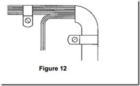
Figure 12 illustrates how wiring from the loop is usually cable tied or laced and then clipped to the door at convenient intervals. Flexible stranded cable should be used covered with an overall PVC sheath, e.g. spiral wrap.
Note: The door of a steel enclosure can be regarded as an exposed conductive part and therefore is required to be earthed. The metal hinge is not sufficient to meet this requirement.
Identification Tags
Cable markers are used to identify cables, wiring systems etc. It is desirable that wiring shall be arranged or marked so that it can be identified for inspection, testing, repairs or alterations of the installation. One practical way of quickly and easily identifying panel wires ( when trouble shooting etc ), is by using cable marking tape. This marking tape, which is purchased in rolls with various legends, is simply placed in a dispenser, which cuts the tape to any length required.
