Building Block Components
Resistors
The humble resistor is by far the most prolific component in use, so it makes a good starting point. A resistor, as the name implies, serves to provide some form of resistance, which is measured in ohms. Even the very name resistor already presents an inkling of what it does. In its very simplest form, as a stand-alone component, a resistor presents a resistance to the current flow that would normally take place when voltage is applied to a circuit. A high resistance presents more of an “obstacle,” so the resulting current flow is relatively small. However, a low resistance allows more current to flow. If a resistor were connected in series with a current source it would be acting as a current limiter. With resistors you can carry out a lot of simple experiments that are easy to understand and explain. For instance, put a resistance in series with a voltage source and a light bulb: as the resistance goes up, the light dims, and as the resistance goes down, the light brightens. What could be easier to understand?
If limiting current flow through a circuit were all there is to a resistor’s function, then we wouldn’t have much of a range of circuits to play with. But human ingenuity being what it is, we (electronics designers) have a lot more uses for the resistor. What can we do with two resistors? As you will soon see, the ingenuity or cleverness of the application is tied into the situation in which the resistor is being put to use.
The sole function of humble light-emitting diodes (LEDs) is usually no more than to produce light and to serve as a solid-state indicator lamp. Driven from a low-voltage source, the LED nevertheless has to have a current-limiting resistor inserted in series
with the voltage source. Where else do we find the innocent resistor lurking? Operational amplifiers, or op-amps, have a devastating amount of power packed into a tiny eightpin dual-in-line (DIL) package. Gain setting, the most common feature for an op-amp, is determined by two resistors. Regardless of the sophistication and variety of op-amps (and there are many), they all have to depend on the lowly resistor to function. A resistor is like the mortar holding the bricks together that ultimately form a house. Mortar’s not much to look at or get excited about, but where would bricks be without it?
Split bias voltages are found everywhere in op-amp circuits running off a single battery. The positive noninverting pin must be biased in order to halve the supply voltage. Two resistors of equal value placed across the supply voltage and ground nicely provide the required split voltage.
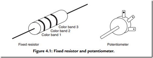
In a slightly different form, but nevertheless still a resistor, there is the potentiometer, which is nothing more than a variable resistor. Figure 4.1 shows the two basic resistor types. All radio receivers, stereo amplifiers, cassette recorders, and other such devices have volume controls for obvious reasons. Resistors come in a variety of practically infinite values, from the typically used values of a few ohms to a few megohms. The LED example uses a current-limiting resistor that can vary from a few hundred ohms to a few thousand ohms depending on the supply voltage and the LED brightness required.
Gain-setting resistors can range anywhere between a few kohms to a Mohm. Resistors for the split bias supply typically are 100 kohms in value. Resistors are usually associated with DC circuits, as we’ve seen, and provide a number of useful functions, but most commonly they control current.
Other than limiting current, one of the next most common functions of the resistor is to act as a potential divider circuit. In the simplest case, two equal resistors are placed across a simple voltage source (e.g., a 9-volt battery). The resistor midpoint is half the source voltage, that is, 4.5 volts. This can be checked with a multimeter set to measure DC volts. Ohm’s law tells us that we can find the current flow in a resistor by dividing the applied voltage by the resistance. The voltage source for the projects in this book is always a 9-volt battery. For the ease of the arithmetic I just round this up to 10 volts. So if we’ve got a 10-ohm resistor, the current is just under 1 mA, actually, it is 0.9 mA, as the current is the ratio of the voltage to the resistance. That quick calculation gives us an idea of what to expect for our meter reading.
The same multimeter set to the ohms or resistance range can be used to check out resistor values. There are two precautions if you’re going to do this now. The first is to: keep your fingers away from the resistor terminals because your body has a finite resistance, more if your hands are sweaty and less if they’re dry. What you’re doing when you touch the resistor terminals is adding your body resistance to that of the resistor you’re trying to measure. The other precaution is to zero the resistance meter first. Do this by shorting the meter terminals and adjusting the “zero knob” until the meter reads zero. You need only do this with the analog type of multimeter.
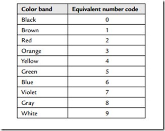
The value of a particular resistance is marked on the component body, typically with a three-color band code. A fourth band represents the tolerance, but for the sake of simplicity you may ignore this if you just want to read off the resistor value (which is generally the case). As you almost certainly will want to be able to read resistor color codes, here they are:
Often people will make up their own jingle to remember the color codes—you know, something that has meaning for you, such as Bye Bye Reba Off You Go Be Valiant Go Well. You get the idea.
The next most common format for resistors, and one that you’ll come across very often in the circuit projects, is the variable resistor or, as it is more usually called, the potentiometer. Relatively speaking, the potentiometer is a much larger device than the
resistor; it is more mechanical as opposed to electrical, and it is a three-terminal device. A rotating shaft coupled internally to a movable wiper track follows an arc-shaped path over a track of resistive material. The movable wiper terminal is brought out to a fixed electrical connection point. Further, two fixed terminals are connected electrically to the other two ends of the resistive track. As you can probably tell, the resistance measured across the wiper terminal and either of the other ends will vary continuously as the shaft is rotated. The maximum resistance value will be the value marked on the device; typically, values of 1, 10, and 100 kohms are used.
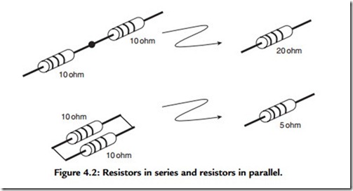
Resistor values will typically run from 1 ohm to 1 Mohm. I find that with most circuit applications you can get away with using just a few “good” resistor values. My own personal preference is 10 ohms, 100 ohms, 470 ohms, 1 kohm, 2.7 kohms, 4.7 kohms, 10 kohms, 27 kohms, 47 kohms, 100 kohms, 470 kohms, and 1 Mohm. If I had to choose the four most useful values, these values can be further distilled down to 100 ohms, 1 kohm, 10 kohms, and 100 kohms. Look at the circuits later in the book and see how often these values turn up. Intermediate values can be built up by juggling a handful of basic values and learning a bit of “resistor math.” Two resistors of equal value connected in parallel produce half the resistor value. So two 1-kohm resistors produce 500 ohms, and two 10-kohm resistors give you 5 kohms. So if a circuit called for a 5.5-kohm resistor and it’s late at night and you desperately need that last component to finish, join two 1-kohm resistors connected in parallel to two 10-kohm resistors connected in parallel, and you’ve got what you need. A useful trick indeed.
The more general rule to follow when the resistors are not equal in value is that for two resistors of unequal value connected in parallel, the total value is the product divided by the sum of the two values. For example, a 1- and a 10-kohm resistor connected in parallel will yield the product 10 X 1 = 1, divided by the sum of the resistor values, 10 + 1 = 11, yields 10 X 11 = 0.9 kohm. Another useful trick to remember when connecting two resistors in parallel is that the total is always less than the smaller of the two values. In the example given earlier, 0.9 kohm is less then 1 kohm (the smaller). For more than two resistors connected in parallel (you can use as many resistors as you want), the rule is total resistance = 1 resistor1 + 1 resistor2 + 1 resistor3 .
Here’s another example. A 1-, 2-, and 3-ohm resistor are connected in parallel. The result is 1/total resistance = 1 1 + 1 2 + 1 3 = 1 + 0.5 + 0.33 = 1.833 ohms.
To check our math, since 1/total resistance is 1.833, the total resistance is 1/1.833 = 0.545 ohm, and this value is less than the smallest value (1 ohm). However, adding two or more resistors in series (end to end) merely gives you the sum of all the individual resistor values. A 1-kohm resistor and a 100-kohm resistor connected in series thus yield 101 kohms. So by combining resistors in series and parallel you could make up almost any value you want. Figure 4.2 shows the series, parallel combination. However, it’s much easier to go out and buy a resistor with the value you want (and that one resistor will take up less space).
Apart from the actual resistance value, there is a second parameter associated with resistors, the tolerance rating, and it is designated by an extra color band. The most commonly specified tolerance is 5% (a gold band), followed by 10% tolerance (indicated with a silver band). In case you encounter them, there are also resistors with no color band that are equal to 20% tolerance, but it is inadvisable to use them because they tend not to be accurate. The tolerance percentage refers to the spread of values on either side
of the nominally marked value (the three color bands) that the resistor is allowed to read and still remain within specification. This tolerance designation gives the resistor manufacturer greater latitude in offering resistors with a nominal value than would be otherwise possible. From the user’s point of view (you and me), this means a 100-kohm resistor might not exactly read that value when measured, but it is perfectly acceptable from the manufacturer’s point of view. For example, if you have a 5% 100-kohm resistor and you measure the actual resistance, it could lie anywhere between
If this were a 20% 100-kohm resistor, then the limits would run from 120 to 80 kohms, which is an extraordinarily wide variation. All the projects described later in the book use 5% tolerance resistors.
The third parameter associated with resistors is their power rating. The value typically used is 1/4 watt, which is also the wattage specified for the project circuits in this book. The power rating of a resistor refers to its ability to dissipate power, which in turn translates to its ability to dissipate heat. The more current you pass through a resistor, the hotter it gets, and the resistor power rating must be sufficient to stand up to the dissipated power. Larger resistors go up to1/2 W and more. It’s a waste to use these for the projects in this book because these resistors take up more space, cost more, and are unnecessary. However, for the sake of demonstrating the calculations involved, I’ll describe what happens to the power rating when we join resistors in series or parallel. In the simple case of two 100-ohm 1/4 watt resistors joined in series, the total resistance is 200 ohms, and the power rating is still 1/4 watt. However, when these resistors are joined in parallel, the resistance drops to 50 ohms, and the power rating increases to1/2 watt—a nice technique to remember if you want to increase your power rating. Let’s say you wanted a 10-ohm 1-watt resistor and the shops are closed. This is quite a large beast. You’ve got a bunch of common 100-ohm 1/4-watt resistors. Take 10 of these 100-ohm resistors and connect them in parallel. The total resistance is now 10 ohms (one-tenth of the individual values),
and the power is increased to 10 1/4 = 1.25 watt. This is another good trick to remember.
Capacitors
Capacitors, like resistors, are two-terminal devices and are distinctive in terms of their ability to block DC signals and pass AC signals. For example, a DC signal, that is, voltage from a battery, cannot be passed through a capacitor, but an AC signal, say it’s coming from transistor radio’s earpiece socket, will pass through a capacitor. A resistor, by comparison, will pass both AC and DC signals by the same amount.
In practical circuit situations there are many instances in which the AC signal has to be passed but the DC component needs to be blocked. One such instance is when a power amplifier’s signal is fed to a speaker. You’ll always see a capacitor feeding the signal to the speaker. Another area in which you’ll always notice the presence of capacitors is at the input and output of AC amplifiers. Capacitors are measured in units of farads, but because these are very large units, the much smaller units of piconano-, and microfarads are most often used. A picofarad is 10-12 farads, a nanofarad is 10-9 farads, and a microfarad is 10-6 farads. The conversion between the units is such that 1 pF equals 10-6 μF.
Remember the simple LED circuit we discussed, the one with the resistor acting as the current limiting device? If the resistor were replaced by a capacitor, the LED would not function because no DC current would be allowed to pass through. Capacitors have a property that is equivalent to DC resistance; they have AC resistance or reactance. The capacitor’s reactance is calculated in ohms (like that of the resistor), and it is a function of the frequency of the signal under consideration. The capacitive reactance is inversely proportional to frequency; that is, as the frequency increases, the reactance decreases.
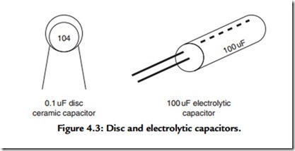
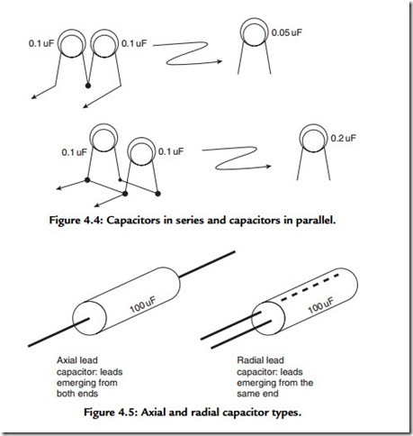
Capacitors can be broken into two basic categories based on their physical structure: the simple nonpolarized type, which is also small in size and small in electrical value (i.e., capacitance), and the larger polarized type, with higher associated capacitance values. Figure 4.3 shows the two basic types. Figure 4.4 shows the series, parallel combinations. Figure 4.5 shows the axial, radial types.
Capacitors such as the electrolytic capacitor are polarity sensitive, which means that they have to be connected in a certain way in the circuit. The electrolytic capacitor is a polarized component, and markings on the body of this capacitor indicate the appropriate negative and positive terminals. As a general rule, capacitors above and including 1 μF in value are usually polarized. Capacitance values for the components with larger values are marked on the component’s body, as there is sufficient space to print out the value in full; that is, 1 μF will actually be printed on the body of the capacitor. The values of capacitors with smaller values are represented with a unique numbering code. The system is similar to the color coding used for resistors, except numbers are used instead of colors. There are three numbers to represent capacitance. It’s much easier to understand the system by way of an example. Let’s look at the code 104. This is a capacitance value expressed in picofarads. The first and second numbers relate to the actual first two digits of capacitance. The final number indicates the number of zeros following. So 104 is 100,000 picofarads. Because this number is a bit unwieldy, multiply it by 10-6 to convert to μF, which works out to 0.1 μF, a much more convenient number to work with. This is a very common capacitor value.
Variable capacitors do exist, but they are used less frequently than variable resistors. But variable capacitors are still two-terminal devices. Why? Variable capacitors operate on the principle of varying the overlap between two metal plates, separated by either air or an insulator—the greater the overlap, the greater the capacitance. So you see, just two terminals are needed. There are no variable capacitors used in the projects in this book.
Radial lead capacitors have leads emerging from one side of the body, and if you don’t have any height restrictions in your project case, this is the type I recommend you use. Axial lead capacitors, however, have leads emerging one from each end of the body of the component. They take up an awful lot of board space and are used only when the assembly board profile has to be as low as possible, but this is hardly a requirement for simple single-IC hobby projects. (An example of a requirement where you would need a very low profile would be for a pager. Pagers are thin as we know and therefore need an assembly board with a low profile.)
Like resistors, capacitors can also be connected in series and in parallel to form different values. However, the rules are different from those for resistors. To increase a capacitor value, we connect two together in parallel. So two 0.1-μF capacitors connected in parallel give us 0.2 μF. Three capacitors of 0.1 μF value each connected in parallel give us 0.3 μF, and so on. If the capacitors were to be connected in series, then
Hence the capacitance is 1/20 = 0.05 μF. Sometimes for timing applications in an oscillator circuit, you might want to change the output frequency a little, and this is one way of obtaining a 0.05- or 0.2-μF capacitor if you don’t have one handy (and it’s too late to run out to your local component store).
For AC applications, an approximate counterpart to the resistor is the capacitor. Again, a seemingly innocent two-terminal device, the capacitor appears lowly in form, but it is critically needed, like the resistor. Consider any amplifier circuit as an example.
Returning to the AC amplifier example, there is always a capacitor coupling the signal in and coupling the signal out. That’s the way to recognize an AC amplifier by the presence of the capacitor at the input and the output. For simple preamplifiers, the coupling capacitors, as they’re called, could be around 0.1 μF in value. If we assume the signal to be in the audio frequency range, say 10 kHz, then the capacitive reactance works out to be 159 ohms. This is very low and practically a short circuit. As the capacitive reactance scales inversely with the capacitance, doubling the capacitor to 0.2 μF will reduce the capacitive reactance by half to 79.5 ohms. In our example of the split supply with the resistor we saw that two resistors of equal value gave us the split voltage. Generally in an actual working circuit, you will see a capacitor placed across the lower resistor, that is, the one connected to ground. This is typically a capacity with a large value (100 μF), which is really a short circuit at the audio frequencies we are working with. Another very common way of connecting a capacitor is directly across the supply line, that is, between the plus and the minus voltage rail. With a battery supply this is not so critical, but if you’re using a low-voltage line adapter, using a large value smoothing capacitor (several 1000 μF in value) will aid in producing a smoother supply source.
Diodes
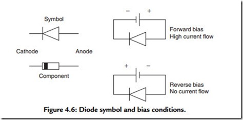
Diodes are two-terminal devices that have a feature that is totally distinct from the features of resistors or capacitors. They are distinctly polarity sensitive. When DC voltage is applied to a diode, a high current will flow in one direction, but reversing the voltage will, to all intents and purposes, cause no current to flow. Put another way, when the diode is configured in what is called the forward-biased mode, the diode will conduct current. Reverse the bias to the reverse-biased mode and no current will flow. This is defined as a rectifying action. AC voltage, say originating from the line voltage, can be immediately converted into a DC voltage of sorts by feeding it through a diode. The diode essentially passes on only half of the positive and negative going waveform. Electronic circuits are invariably powered with the positive voltage supplying the power rail (Figure 4.6).
To test this out, connect up a resistor, say 100 kohms, across a 9-volt battery with a current meter inserted between the positive battery terminal and one resistor terminal.
Make sure the current meter’s positive terminal goes to the battery’s positive terminal. The current will be just under a tenth of a milliamp. The actual current value doesn’t matter. If the meter’s needle kicks against the end stop, reverse the meter polarity (assuming you’ve got an analog multimeter); a digital multimeter will automatically compensate whatever polarity is present. When using a digital multimeter to measure DC voltage, there is no need to worry if you get the test leads reversed. The multimeter will still show the correct voltage; there’s just a negative sign in front of the numeral. That tells you that the multimeter red test lead, for example, has been connected to the negative voltage potential. There is no damage done to the digital multimeter. If you now take the feed of the positive battery terminal via a diode (it doesn’t matter at this stage which way round it goes), one of two things will happen. Either the current will be the same as before or the current will be zero. Whatever it is, take note of it. Then reverse the diode polarity; just reverse the diode’s connection in the circuit. An effect opposite to the one you first observed will now take place. You’re seeing the rectifying action of the diode.
One really useful function for the diode is as a protective device. Electronic circuits are invariably powered with the positive voltage supplying the power rail. If the voltage is inadvertently reversed, there is a high probability that the components will suffer some damage. Placing a diode (this would be a power type called a rectifier) in series with the positive supply voltage would do the trick. When the polarity is correct, insert the diode in such a way that current starts to flow (trial and error is the quickest way to learn which way to attach the diode if you’re not sure about the markings). Now if the voltage polarity should be reversed, no current will flow, thus providing the protection. Try it and see.
Transistors
Transistors are totally different from resistors, capacitors, and diodes. The latter are what are termed passive components, performing a singular function as we’ve seen, useful certainly, but not active in the electronic sense. A transistor is a truly active device. It can take a signal and amplify it. A number of support components are needed to make the transistor into a working amplifier—you guessed it, using a few resistors and capacitors again. Depending on the designer’s talent, transistors can be configured into an endless string of circuits, amplifiers, oscillators, filters, alarms, receivers, transmitters, and so on. The versatility of transistors knows no bounds.
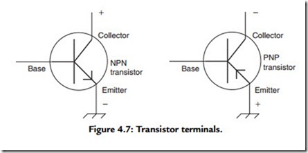
Although I do not include transistor-based circuits in this book—the reason being that integrated circuit projects are so much more well behaved and therefore simpler to design—I do provide a brief overview on transistors, as integrated circuits are really just a huge collection of transistor-based circuits. Transistors are three-terminal devices; the terminals are known as the emitter, the base, and the collector. Figure 4.7 shows transistor details. Transistors come in two “flavors” so to speak: the more common NPN type operates with a positive supply voltage, and hence, it is very compatible with integrated circuits, which almost always run on a positive supply. The less common transistor type is the PNP device, which, as you might have guessed, requires a negative supply voltage (not so commonly found in circuits).
Transistors are defined as active devices because they have the capability, given the appropriate support components, to perform useful functions; the most common of these is amplification, but the other is oscillation. A simple, common emitter amplifier can
be designed around four resistors and a capacitor as well as the usual input and output coupling capacitors. However, there are two main reasons to use the integrated circuit (IC). The amplifier’s performance is influenced by the transistor’s parameters, not so with the IC. Coupling the transistor amplifier into a following stage requires careful consideration of the loading effect. An IC-based amplifier just gets coupled into the next. The IC amplifier is such an effortless pleasure to use. The input, output, and gain are so nicely controlled. You would have had to have labored through the transistor’s design quirks to really appreciate how much more controlled the IC is.
Transistors come in a huge variety of types, from general-purpose, small signal (the most common) to large power devices. The frequency range of operation can extend from DC to audio all the way up into the microwave range. Transistors are not as easy to evaluate as ICs. Put together a few resistors and capacitors around an IC and you’ll soon know if the circuit is working (and it usually is), as you don’t have to even wonder if the IC itself is working. However, try the same with a transistor, and you’ll find that determining whether or not the circuit is working is a lot harder. Was the transistor the right type? Was the bias network correct? Is the circuit design right? If the transistor circuit doesn’t work, you’ll always wonder whether the transistor itself is okay for the application. Isn’t it great to know that in the majority of cases, you need only ask for one IC (the LM 741 as it turns out) when working with ICs. Enough said about transistors. They have their uses in specific applications, but you’ve got to be a bit more circuit smart.
Other Components
Integrated Circuits
The integrated circuit is an amazingly robust bullet-proof device, by which I mean that you can put practically any design around the IC and know that it is going to behave itself—okay, behave itself within reason, but ICs are brilliantly transparent compared to transistors. A small handful of resistors and capacitors and, hey, presto, we’ve got a well-behaved amplifier. The transistor could never match that! I know the comparison is a little unfair, especially because the IC itself is composed of a very carefully designed collection of transistor-based circuits, but we’re talking user-friendliness here. I recall the difficulty I experienced way back in the mid-1960s getting a simple half-watt transistor power amplifier to function properly. The component count was high, special parts were difficult to come by, setup was tricky, and current consumption was high. Now we’ve got the LM 386 audio power amplifier on a chip! It’s actually been around for a considerable number of years, but it is still very widely used. One IC and two capacitors and you’re in business—wow! The current consumption is pretty good, too. The LM 386 IC is an example of a special function IC that is designed to deliver (which it does admirably) just one unique function. The unique one function for the LM 386 IC is as an audio power amplifier. It’s hard to believe that a small eight-pin plastic part, a little bigger than one of the buttons on your TV remote, packs such a technological punch. This particular IC runs nicely off a regular 9-volt battery—there are no weird dual supplies to worry about. Many of other higher power ICs require dual supplies, or voltages of 12 volts and higher (a 12-volt battery that you can’t buy off the shelf and that would fit in a project case), and consume masses of current.
Integrated circuits fall into two broad categories: analog and digital. They are very easily recognized in terms of their functionality and also in terms of the way they’re depicted in circuit schematics. Analog ICs process mostly AC signals, but they also process DC signals. The absence of a coupling capacitor at the input would signify that this is a DC amplifier we’re looking at. A DC amplifier has to be capable of amplifying DC signals as well as AC signals. Analog signals, such as audio signals, require coupling capacitors at the input and output because only AC signals are allowed to be coupled through the amplifier. The presence of coupling capacitors removes the DC components. The schematic is also drawn in the form of a sideways triangle representing the IC. Input goes into the wide end on the left and exits as an output from the pointed end on the right. In essence, all analog IC blocks resemble this basic form. Typical examples of analog ICs are the LM 741 general-purpose op-amp in an 8-pin DIL package and the LM 324 quad op-amp package in a 14-pin DIL package. When space is at a premium, the LM 324 is a superb device; it is especially suited for audio applications and occupies far less board space than do four separate LM 741s. Analog ICs, incidentally, are also called linear ICs. Digital ICs only use two voltage states, a logic high (1) and a logic low (0). There are no capacitors in the signal coupling lines, and the schematics are generally drawn in the shape of rectangles or squares. Typical examples can be found in the 7400 series of digital TTL ICs. There are no digital ICs used in this book, but it’s worthwhile to make a quick mention of them here because they’re such a major portion of the IC family.
The third group of ICs covered in this book are special function ICs, that is, devices falling into neither the analog nor the digital category. Analog or digital ICs don’t really do anything by themselves, so to speak. To turn an LM 741 into an amplifier (which is
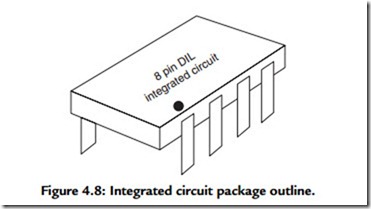
usually the case), you have to adjust the rest of the circuitry. Alternately the 741 could be designated as an oscillator, and again it is changed accordingly. Digital ICs operate on the principle of responding to just two voltage levels, a low level (also called a ‘0’) and a high level (also called a ‘1’), and hence, are also called logic devices. Digital ICs can be thought of as a series of logic gates that are configured to perform a certain logic function. Special-function ICs are complete in themselves. The LM 386 audio power amplifier that we’ll be focusing on heavily later in the book is just that; it is a self- contained unit that is designed to perform just one task (and it does so admirably at that). Another much-used special function IC is the LM 555, a timer IC, so commonly used to provide a train of square wave pulses. Figure 4.8 shows the basic IC outline.
Switches
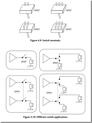
Switches occur in so many places despite their somewhat mundane nature. After all, a switch is just an on/off device. There are actually many different configurations for switches, and it’s a good idea to get to know the variations. First of all, there’s a terminology specific to switches: poles and throws. The simplest type of switch, like the type you’d find in a lamp switch, is called a single pole, single throw, or SPST switch. The simple SPST switch has two terminals, one of these goes to the source (this being typically the positive voltage supply from a battery) and the other goes to the output (typically this would be the circuit that is to receive the power from the battery); hence, the output can only be connected to one terminal. It also has a toggle that flips back and forth. The light flips on one way and off the other. Switches always have to be described with respect to an input signal and an output signal. The pole refers to the number of terminals the input can be connected to. With the SPST switch there is just one. The throw refers to the number of terminals the output can be connected to. In the SPST switch there is just one. What if we had two terminals to which the output could be connected? Because there are now two throws, this kind of switch is called a single pole, double throw switch. In this switch there are actually three terminals arranged in a row. The input attaches to the center terminal, and the other two terminals go to the two outputs. The SPST switch, as we’ve seen, is the type used to switch an appliance on and off. The SPDT can be used to switch either one of two lights on. This kind of switch is not too useful in real life, as there is a chance you may want both lights off. But it illustrates the point. Incidentally, there is a less common type of enhanced version of the SPDT switch with a center off position. The toggle is biased mechanically so it can be positioned in between the two extreme positions. That switch will turn off either light (in our example). In the aforementioned example we have had the switch connected just in the positive supply line (where it is usually connected). The other terminal, that is, the negative terminal, if we were considering, say, a battery being hooked up to a light, would be permanently connected into the circuit. In situations where both sides of the battery need to be switched, we use a switch that is essentially a dual version of the SPST switch. This switch has two sets of terminals, each set identical to the other in function. As you might have guessed, this is a double pole, single pole, or DPST switch, where a pair of inputs can be switched to a pair of outputs. This switch type is useful because it makes possible more than just the basic on/off function. An even more versatile switch is the double pole, double throw, or DPDT switch, where two separate inputs can be switched to two separate pairs of outputs.
Table 4.1 illustrates the use of the different switch types. Figures 4.9 and 4.10 depict the switch types very clearly.
The dotted line for the DPST and DPDT switches indicates that these switches have ganged contacts, that is, they are switched together with each mechanical toggle. For a seemingly simple mechanical device, there’s certainly more to the humble switch than you
first thought. Apart from the switching differences, switches also come in different current ratings; the higher the current capacity, the larger the physical switch. For the circuit projects shown in this book, choose switches with the smallest current ratings available. Here’s a very useful tip that I only found through experience: some small switches (the toggle type) require a huge amount of force to toggle between positions. What this means is that if you’ve got a very light plastic project case with this type of switch mounted on the front panel, you will most likely tip over the case when you try to flip the switch. I found this out the hard way! So choose small switches that have a very light toggle action. A slight flick of your finger should flip the switch to the other position. Switches are quite costly, and you can save yourself a bundle by not buying the wrong type.
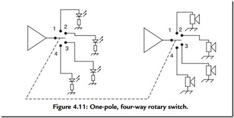
Rotary switches are like super versions of the regular switch and are defined by poles and ways. For example, a simple, one-pole, four-way switch will switch one input signal to one of four outputs. Let’s say we had a two-pole, four-way switch. This switch has two sets of independent contacts that can be coupled to one of four positions. Let’s say one pole was used to switch a radio output to one of four speakers. To know which speaker was being powered, the second set of contacts could be wired to four LED indicators, marked as 1 to 4. Each LED would then light up, corresponding to its matching speaker. This setup is shown in Figure 4.11.
Jack Plugs and Sockets
Audio connections are made much neater and easier with the use of miniature 1/8-inch jack plug/jack socket combinations. If you’re using a jack plug, you’re going to need a
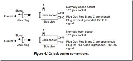
jack socket. This size of jack plug is almost always found with the headphones provided for portable radios and cassette players. Now you know the size we’re talking about. These aren’t the huge jack plugs used with electric guitars. The jack plug has a screw-on barrel, often plastic but sometimes metal. Once you remove the cover, and if it’s a mono plug, you’ll see two connections. There’s a short connection to the center pin and a longer connection that goes to the ground terminal. You can recognize a mono jack plug by the single insulator strip near the end of the jack plug tip. The stereo jack plug has two such insulator strips. Jack sockets come in the normally closed and normally open types. In
the normally closed type of jack socket, there are two contacts that are in mechanical and electrical contact, that is, it’s normally closed. The action of inserting the jack plug causes the two contacts to mechanically spring apart, so the electrical connection is broken. When you remove the jack plug, the electrical connection is made again. The normally open type of jack socket has two close-by terminals that are not electrically connected
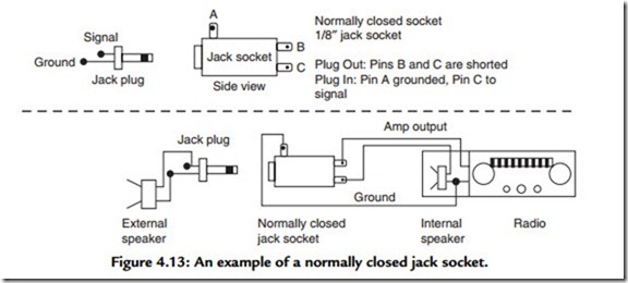
to each other. When a jack plug is inserted, these two contacts are mechanically brought together and as long as the jack plug remains inserted, the electrical connection is maintained between the two terminals. Figure 4.12 shows the differences for one particular type of popular socket. For the basic application, such as connecting a speaker to an amplifier output, it makes no difference which type is used. But the normally closed type of socket has a special use; it is used where an amplifier is connected normally to an internal speaker, and when an external speaker is plugged in, the internal speaker is disconnected by the action of this jack socket. Portable radios have the same arrangement, whereby plugging in the external headphones disconnects the internal speaker. This
example is seen in Figure 4.13. Like switches, jack plugs and sockets are more complex than they might at first seem.
Light-Emitting Diodes
The LED is today’s solid-state marvel, the equivalent of the filament indicator lamp of years gone by. When I started in hobby electronics, especially in the building of amplifiers, I always had to use filament indicator lamps as power on/off indicators. They took up a lot more space than LEDs, but, more critically, the current they drew was enormous. Fortunately, with the advent of the integrated circuit era came also the
solid-state electronics age, with the LED soon becoming the universal indicator device. Small, light, extremely robust, and drawing an economical amount of current, the LED is a natural for panel indicators. In absolute terms, the current drawn is not insignificant, however, but as the rest of the electronics technology speeds ahead to devices that use much less power, the indicator remains locked (at least for the time being) with the LED. Fundamentally, if the LED is to be used as a relatively long-range viewing device, current has to be supplied to produce the visible light energy. Typically, current through the device is limited with a resistor to just a few milliamps for acceptable viewing. LEDs come in a limited range of colors—red, green, yellow—but red is by far the most common and useful color. They come in different shapes (cylindrical and rectangular) and sizes, from pin-head tiny to jumbo sized, the most commonly used size being something like the size of a TV remote button. There are some special LEDs with very
high brightness levels, but they draw more current than the plain vanilla variety, so unless you really need extra high brightness, be careful when you choose your LEDs. The LED package is sometimes marked with the brightness and current values, depending on where you buy your components. Of course, you can always increase the brightness level a good deal by increasing the current up to its maximum limit, but your battery life will be shortened. There’s always a compromise, isn’t there? Who has ever heard of a Corvette that is also economical to run.
