Programming style
Introduction
‘. . . and the hydraulic system will have three hydraulic pumps plus an oil circulation pump’. So ends a typical specification for a control system. Like most specifications this simple statement leaves many unanswered questions; are all three pumps to be run, or just one, or two? If less than three, how is (are) the duty pump(s) to be selected? If less than three pumps are used, are unused pump(s) to act as standby with automatic changeover? How are pumps started, individually or all together? Does the emergency stop operate on all (if not why not?). Does the circulation pump start with the main pumps, or is it a precondition for starting the main pumps? If the circulation pump trips, should the main pump(s) trip? What protective signals are there (e.g. temperature/level)? If none, why not, and are you sure? Should these stop the pumps or merely produce alarms? Often such questions will reveal that the suppliers have thought only of what equipment is needed, and not how it is to be used.
The designer of a PLC system has to produce a program which fulfils these often poorly defined requirements. Allied with this is the need to assign I/O to plant signals and operator controls, and decide how the all-important link between human beings and the plant is to be performed.
Programmers involved with commercial software have similar prob- lems, and have coined the term ‘Software engineering’ to describe how a software project goes from the user’s original (and probably imprecise) ideas to a successful working system. In this chapter we will examine the factors that need to be considered in the design of a PLC control system.
Software engineering
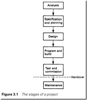
Figure 3.1 shows the six stages that any software project must go through during its life. Although few projects are compartmentalized as neatly as this, the principles apply to all.
The first stage is analysis of the problem that is to be solved. The supplier/programmer of the PLC system must meet with the other contractors and the user to determine what controls are needed and how the control actions are to be provided. Important considerations such as operator controls need to be established at this stage. Ambiguous descriptions (such as the hydraulic pumps of Section 3.1) should be resolved.
Of all the stages, analysis is the most difficult, as the ultimate end-user and the other contractors probably have not considered the intricacy of the control strategy, and do not have the experience to decide if an item of plant is best controlled with joysticks, pushbuttons or a touchscreen VDU.
An important point which is often overlooked at this stage is the need to provide some form of manual ‘maintenance’ controls to test, or rescue, a fully automated plant or sequence which has failed in some obscure manner.
The output from the analysis stage should be a description of how the plant works, what operator stations and controls are needed (and how these are to be implemented), what maintenance/fault-finding aids and facilities are to be included and finally (but not least) a complete list of the I/O signals with voltage/current specifications and their locations on the plant.
The difficulties (and the importance) of this first stage cannot be over- emphasized. If the ambiguities and problems are resolved at the start, the following stages are easy. Finding out at the commissioning stage that the user wanted variable speed fans and an underpressure alarm and ‘thought you knew that’ is not the way to ensure a smooth plant start-up. If in doubt, ask; even if you are not in doubt, still ask, and assume nothing.
At this stage, the final testing requirements should also be defined. If you do not know how you are going to test it, how will you know if the plant meets the user’s requirements?
With the worst stage over, the designer should produce a description of what the control system contains, how it is going to perform and how it will be tested. This is really recording what was agreed at stage 1.
The next stage is to design the system; the cubicles, desks, and the structure of the program. This latter action, known as top-down design, is considered in the following section.
At last the programming can be done, built around the structure laid down at the design stage. No program should be constructed ad hoc at the keyboard; that way lies spaghetti programming. Commercial programmers estimate that this stage generally involves no more than 10% of the total effort.
With the programming completed and the plant built, testing and commissioning can start. The operation should be checked against the specifications produced at stage 2. With all bar the simplest system, it can be very time consuming to check all routes and actions given in the specifications. There is generally pressure to ‘hand over’ the plant when the basic operation has been tested but the ancillary, rarely used, options are untried. Too often these tests are skipped, and the first time a ‘firkling fault’ mode is tested is when the ‘firkling fault’ first occurs, possibly years after the plant has started up. Inevitably, commissioning of the control system will always be the last stage in a new plant, so the control engineer ends up carrying everyone elses’ delays. It is therefore important to establish what testing must be carried out before a plant can start and what can be tested later, on line. On line testing, however, can be very difficult and time consuming.
Safety-related checks should never be skipped; finding out that an emergency stop sequence does not work when it is used for the first time in an emergency will ensure a visit from the Health and Safety Executive.
The final stage is usually overlooked. Once the plant is handed over, its control system must be maintained, a term used here not to mean serviced in the mechanical sense, but covering fault finding, resolving of bugs (‘we never meant it to work like that’) and (hopefully minor) changes arising from modifications in the way the plant operates. No plant is fixed, all change during their life in response to market or technology changes, and these modifications require changes in the control strategy.
In commercial programming it is generally thought that maintenance takes over 50% of the effort in a project’s life cycle. It is therefore essential that the control strategy and program are constructed and documented so they can be changed and modified easily at a later stage, possibly by people who had no involvement with the previous five stages.
Top-down design
It is not uncommon for a PLC to contain several thousand ladder rungs or logic segments. An unstructured program of this length can be very difficult to write, and even more difficult to follow for maintenance and fault finding.
The programmer should not, therefore, write a single long program, but break it down into many small program segments. Ideally, each small segment should contain no more than ten ladder rungs or logic elements as this is about the maximum that the human mind can hold at any one time. The structure of these segments is one of the more important aspects of the design stage of Figure 3.1.
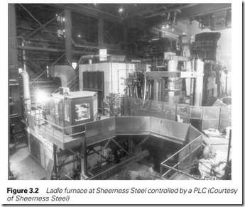
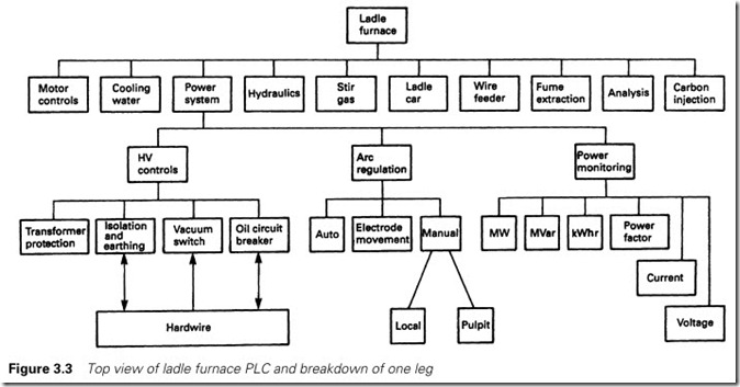
The best way of achieving a sensible split is to use a technique called top-down design. This splits a control system into areas, which are subdivided into sub-areas and so on until manageable sizes have been achieved. The idea is best shown by an example. Figure 3.2 shows a plant called a ladle furnace. This is controlled by a single PLC with about 1750 ladder diagram rungs.
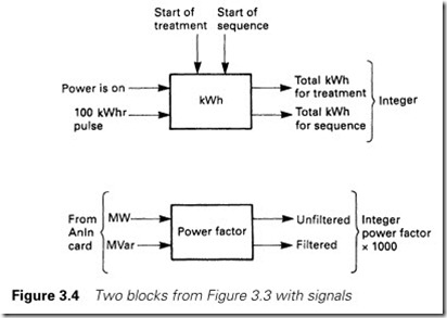
The plant control can be broken down into the nine areas of Figure 3.3, each of which can be broken down further, the full structure of the power system being shown. The bottom levels can be programmed in a few rungs. Figure 3.4 shows two of the bottom level blocks and their plant and internal signals. The kWh block, for example, consists of two counters stepped by the 100-kWh pulses from a power transducer when the power is on (an internal signal from another block). Both counters are reset at the start of a treatment, and the sequence counter is reset at the start of a new sequence. The output of the block is two totals used by other blocks for operator displays and automatic control.
The resulting program structure should be recorded as part of the control system documentation, and used as the foundation of the actual
programming effort. One, not immediately obvious, bonus is that a well-laid-out structure chart with signals clearly identified can be easily split amongst several programmers.
Program structure in various PLCs
In high level computer languages, programmers tend to prefer languages such as Pascal or C, which are inherently structured by their inbuilt constructs, and view ‘non-structured’ languages such as BASIC or FORTRAN with a certain amount of disdain. To some extent this is unfair; it is possible to write perfectly structured programs in BASIC, but the onus is on the programmer, and a Pascal or C program can easily degenerate into spaghetti without due care.
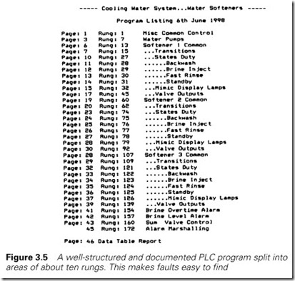
Similar observations apply to PLC programs. Many middle-range machines (and all small machines) have no built-in structure elements at all, leaving it to the programmer to decide on the layout and follow a self-imposed discipline. Figure 3.5 shows an index for a small PLC system controlling a three-unit water softener; the program structure is
straightforward, and a fault on, say, Unit 2 Fast Rinse, could easily be located in the program.
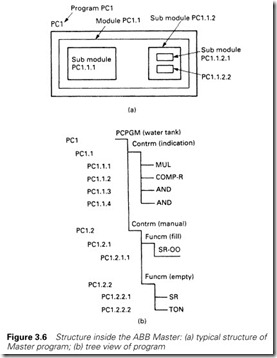
Larger, and more modern, machines have built-in structure constructs. To some extent these constrain the programmer in the same way that a programmer in Pascal or C has a lot less freedom to make mistakes. These PLCs generally provide methods for breaking the program down into small understandable modules (with some larger machines such as the Allen Bradley 5/250 having the Repeat/Until, Whiledo/Endwhile, For/Next constructs for repeating the same operation on a block of data). The most structured language is, possibly, the ABB Master, which is similar to a compiled high level language in that all variables and proced- ures need to be declared. The PLC program is split into one (or more) programs labelled PC1, PC2, etc. It is recommended that each deals with a different area of plant, and each program can have different scan rates. These programs then contain control modules which can be enabled/ disabled or again run at specified time intervals. Within the control modules there are function modules and sequencer modules, the latter containing steps corresponding to the state diagrams described in Section 2.9.2. The actual logic elements are contained in the function modules or the sequencer steps. A complete program can thus be viewed as in Figure 3.6(a) with a specific example being laid out rather like an MSDOS or UNIX tree as in Figure 3.6(b). The actual structure is more flexible than this description implies; function modules can contain control modules, and a hierarchy of master/slave modules can be built, but the basic idea should be apparent.
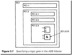
Modules are labelled in a hierarchical manner down to the element level, so the AND gate PC1.2.3.2 is the second logic element in function block 3 of control module 2 of program PC1 (and has to be declared as such as part of building the database) (Figure 3.7). This formal nature imposes a discipline on the programmer.
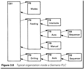
Siemens use a structure consisting of organization blocks (OBs), program blocks (PBs), function block (FBs), subroutine files, which we will discuss shortly, and sequence blocks (corresponding to state diagrams). The basic building modules are the program blocks which equate to the bottom units of top-down design. When first started, the machine com- mences with organization block OB1 from which further PBs and FBs can be called, as in Figure 3.8. This description is again somewhat simplified.
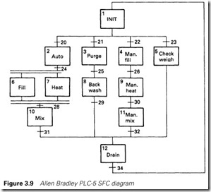
Allen Bradley use a similar idea with the PLC-5. The programmer can break the top-level program down into smaller program modules which can be called as needed. In the PLC-5, the programs are linked by a sequence function chart (or SFC) which is again very similar to the state transition diagram described in Section 2.9.2. Each state and transition is a small ladder diagram program, a typical example being given in Figure 3.9.
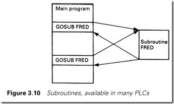
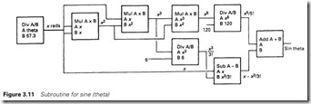
Allen Bradley and Siemens both support the concept of subroutines (called function blocks (FB) by Siemens). These are small programs used to perform specific tasks which can be called repetitively by higher level programs (Figure 3.10). For example, few PLCs support trigono- metrical functions (sine, cosine, tangent) directly. It is relatively easy to calculate the sine of an angle using the expansion series
where x is the angle in radians. For most applications the first three terms will give sufficient accuracy. The sine of an angle theta (in degrees) could therefore be found with a sequence similar to Figure 3.11 achieved with a few ladder rungs or logic segments. Let us make this
a subroutine called Sine (what else?) with an input angle in degrees, and returning the sine to the designated variable as Figure 3.11. The input and output variables are called parameters. Whenever we want the sine of an angle we can now call the subroutine program Sine.
We can go further, though. The cosine of an angle is given by
cos (theta) = sin (90 – theta) (3.2)
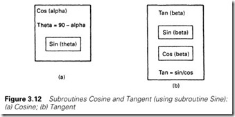
where theta is in degrees, so we can write another subroutine to calcu- late the cosine of an angle as in Figure 3.12(a). Note that this only has two blocks, and calls the subroutine Sine (which does most of the work).
Finally, by observing that tan (theta) = sin (theta)/cos (theta) (3.3)
We can construct a Tangent subroutine as in Figure 3.12(b). This calls both the Sine and Cosine subroutines. A subroutine calling further subroutines is called ‘Nesting’.
The advantage of subroutines, of course, is the saving of processor memory and the minimization of programming effort. They also make the program easier to follow, as the maintenance staff or the programmer making changes only need to examine a (possibly complex) routine at one place only.
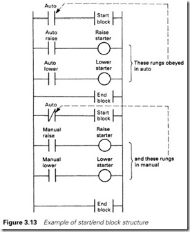
Many PLCs allow a program to be split into executable blocks; in Allen Bradley PLC-5s, for example, this can be done with an MCR instruction (for Master Control Relay) and in GEM-80s a Start/End Block command can be used. These allow a set of rungs to be skipped (ignored) if the controlling instruction at the start of the block is not true, as shown in Figure 3.13. These instructions again serve to structure the program into small blocks, and also help to improve the scan time by ignoring rungs which are not relevant at the current time. They can,
however, cause confusion to maintenance staff in the middle of the night as the split of the program is not immediately obvious.
Housekeeping and good software practice
All computer software (whether data processing, commercial or control) should:
(a) perform its function reliably
(b) behave in a predictable defined manner when the incoming data are faulty (a behaviour described as ‘robust’ in the jargon)
(c) be simple to understand and maintain
The first of these requirements is obvious, and most PLC software will (hopefully) do the job for which it has been designed. The other two points,
however, are often overlooked, and their absence may not be apparent until the first time a problem occurs months (years?) after the plant has been commissioned and the design team disbanded.
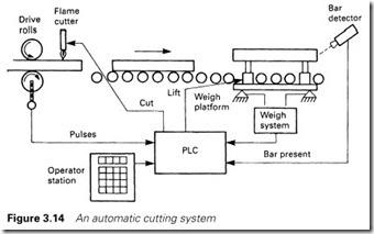
Robust software has inbuilt protection against bad data from faulty plant sensors or miskeyed operator inputs. Figure 3.14 shows an applica- tion based on a system at the author’s plant. Material is supplied to a customer’s specified weight, but is cut by length, by counting pulses from the drive rolls. The operator enters a desired weight, and the PLC converts this to an equivalent length. The resulting cut material is weighed and checked against the desired weight, any error being used to correct the next cut.
This system contains many places at which bad data can occur; bad operator input giving a ridiculous weight, bad readings from the weigh system, electrical interference on the pulses from the drive rolls, to name but three. Any of these could cause problems if the resultant faulty data were handled as being correct.
It is essential to include some form of checking. The operator in Figure 3.14 can only enter weights within a specified range, and only readings from the weigh system within a window specified as a percent- age of the target weight are used for the trimming function. Bad operator input or weights outside the ‘window’ are flagged as system alarms. Similarly a time window for cuts can be calculated, with pulse-initiated cuts only being allowed within this window and an emergency time cut being initiated (and an alarm signalled) if no pulse cut is given before the maximum time occurs.
Inevitably, robust software is more lengthy and complex; about 25% of the software for Figure 3.14 is concerned with normal operation, the remaining 75% dealing with abnormal conditions that may rarely (if ever) occur. The protection is essential, however, to give operators and pro- duction staff confidence in the system.
Programmers take a certain perverse pride in the ingenuity of their efforts and the minimization of the number of instructions used. Such tendencies should be resisted even more than in commercial program- ming, as the actual plant and program maintenance will be done by people who will require clarity of operation. ‘Keep it simple’ should be the motto; do not use complex methods and steer clear of the more obtuse instructions available in a PLC instruction set. Remember that some poor individual may have to see how it all works at three o’clock in the morning.
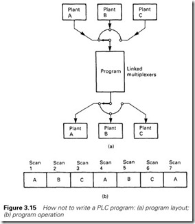
Figure 3.15 shows an example from my experience of how not to write a PLC program. This application had one PLC controlling three identical plants. The programmer started by constructing a software multiplexer, effectively a three-way rotary switch, which copied all the inputs for one selected plant to internal storage locations. There was then one program (for all three plants) which worked on the internal storage, and sent its outputs to internal storage again for sending to the outside world via a software de-multiplexer. The multiplexer and de-multiplexer were stepped per program scan, so the program dealt with plant A on scan 1, plant B on scan 2, plant C on scan 3 then back to plant A on scan 4 and so on. This was very clever and economical of memory, but impossible to understand and fault find. In normal oper- ation the operation could not be followed, as all that could be seen on the programming terminal was a blur as the multiplexers cycled between the different plants. When a plant failure occurred, the multiplexers had to be locked into the faulty plant (shutting down the good plants) to allow the operation to be observed. Tricks like this should be avoided (and it is worth noting that this particular program was rewritten completely within a year).
The program should also try to reflect the plant operation. Figure 2.48 showed a common situation where either or both of two motors are to be run as selected by a desk switch. For economy, a less than ideal switch has been used. The simplest program is the single rung of Figure 2.48(d) but I would suggest that the two rungs of Figure 2.48(c) make the operation clear to the person encountering it for the first time.
Good documentation is essential for clarity. Most PLCs can be programmed offline on an MSDOS computer, and have the facility for individual signals to be documented and explanatory comments added to explain how the program works. This feature should be used fully;
compare the undocumented program of Figure 8.38 with the annotated version of Figure 8.39.
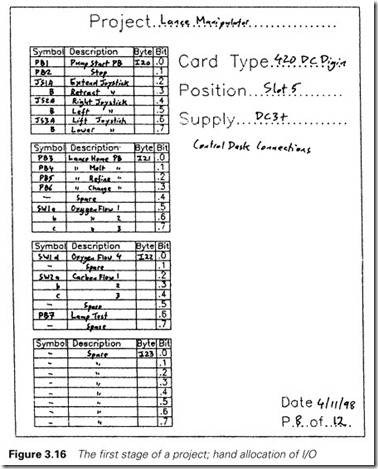
One of the standard rules for all computer programming is ‘when you put some data in memory, record where you have put it’. Failing to do this is like shoving something in a cupboard then being unable to find it a few weeks later. All use of I/O and internal storage should be recorded. Annotation at the programming state helps here; if you have chosen an internal store bit to represent ‘Water Overtemperature Alarm’ and when you call it up in the program the annotation ‘Pump-1 Trip’ is attached, you know the same address has possibly been used twice or the memory map is off the rails somewhere.
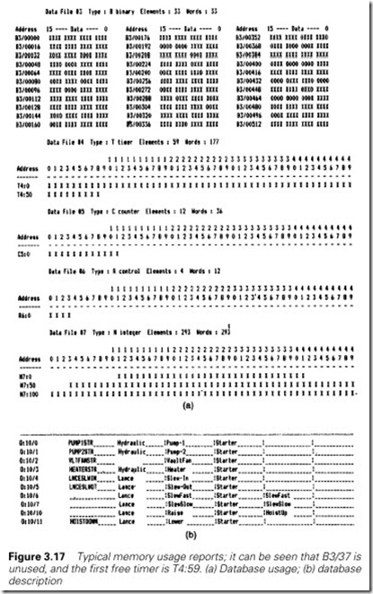
PLC manufacturers provide store and I/O allocation charts similar to Figure 3.16. These should be used meticulously. MSDOS-based
programming software invariably provides a printout of memory usage, one example of which (for an Allen Bradley PLC-5) is shown in Figure 3.17.
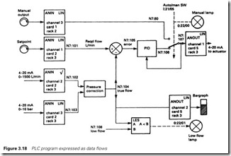
If the interaction of data in a program is complex it is worth producing diagrams of data flow such as that shown in Figure 3.18. Such diagrams help the planning of the software, and assist greatly in fault finding and maintenance.
It should always be the aim to make the task of the people who inherit the PLC as easy as possible. One way of achieving this is consist- ency of programming style. If a motor starter has been programmed in a certain way at one point of the program (checking, say, for tripping of the motor protection and operation of the auxiliary contact), this style and method should be repeated for all other motor starters. Particular care over consistency needs to be taken where different parts of a pro- gram are being written by different people, and a ‘house style’ is worth developing. The Ford ‘EDDI’ concept discussed in Chapter 8 is one example of this approach.
Speeding up the PLC scan time
A typical PLC scan time will be 10 to 20 ms. This is adequate for most applications linked to contactors, solenoids and similar electromechani- cal devices. If, however, the PLC is being used with fast moving material the scan time, and more important the variation in the scan time, can be very important. For example, if a PLC is being used to cut material to a set length, and the material is travelling at 10 m/s, a 15 ms variation in scan time will correspond to a 150 mm variation in the length. This section looks at factors which affect the scan time and ways of improving the speed.
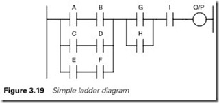
Figure 3.19 shows a typical rung. Most PLCs will scan this in the order:
A, B, C, D, E, F, G, H, I,
then update the output. To speed up the scan, though, most PLCs will skip branches once they have found a branch that is true. If signals A and B are true signals C, D, E and F will not be examined and signal G will be tested after signal B.
In the best case, with A, B, G and I all ‘1’, just four contacts have to be examined before the output is energized.
In the worst case, with A, B, C, D and G all ‘0’ and the remaining signals all ‘1’, all nine contacts have to be examined before the output is energized.
Similar considerations apply when determining if the output is to be de-energized. If A, B, C, D, E and F are all ‘0’, the output can be de-energized immediately without examining the state of G, H or I.
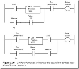
To get fastest speed, therefore, signals which will most probably be ‘1’ or whose presence requires the fastest response should be placed on the top of rungs and nearest the left-hand side. If there is a pair of rungs whose outputs cannot occur together (e.g. Auto Raise and Manual Raise) put the selection signal (e.g. Auto and Manual) as the first contact in each rung so only one contact is examined in the unused rung. Similarly a rung arranged as Figure 3.20(a) will operate faster than Figure 3.20(b). Note that in the slower rung, time has been wasted by repeating the top limit switch signal in each branch.
Repetition of signals is a common error and usually occurs with per- missives. The fastest way to handle these is to group all the permissives together once into a permissive store then use this store in each rung with requires the permissive.
Mathematical operations are much much slower than bit operations, and floating point operations are slower than integer operations. If speed is important try to do all mathematical operations using integer numbers, but care obviously has to be taken to avoid rounding errors and overspills. A sixteen bit two’s complement number can cover the range -32 768 to +32 767.
Mixed floating point and integer arithmetic should be avoided as these have conversion overheads. For example with the simple arithemetic operation Int2 = Float1 + Int1 the PLC will first convert Int1 to an internal floating point number, add it to Float1 to give a floating result then convert this result back to an integer to go into the integer result Int2.
Many arithmetic operations only have to be done rarely, some only once at power up. A lot of time is wasted if arithmetic instructions are obeyed on every scan. Only do arithmetic operations when they are required.
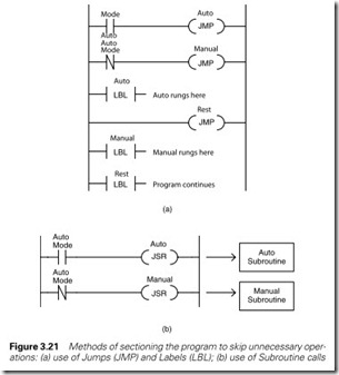
Many PLCs have control functions which can be used to reduce the scan time. The commonest of these are Jumps which allow unused parts of programs to be skipped as Figure 3.21(a). Subroutine calls can be used in similar way with selected subroutines being called only when required as shown on Figure 3.21(b). Both of these can make major improvements but it should be noted that this can be confusing for people trying to follow the program in the early hours of the morning as rungs which are skipped or live in uncalled subroutines may appear to indicate a PLC fault.
Some PLCs have specific program files which can be allocated a specific scan time. The PLC5 family, for example, can have a Selectable Time Interrupt (STI) program which is obeyed at a fixed time interval which can be as short as 1 ms. With a main program scan of 20 ms, the STI file could operate twenty times for one main program scan. This speed, though, comes at the expense of the main program scan so STI and similar files should be kept as small as possible to avoid dragging the rest of the program files down. Many PLCs, of which the ABB Master is typical, allow scan times to be assigned independently for each and every program file in the processor.
As explained in Section 2.2 and Figure 2.2 a PLC normally goes through a scan which at its simplest level is:
Read Inputs Obey Program Update Outputs
Using tricks like STI files is not much use if you have to wait until the end of the main program scan before the outputs are updated. Control functions with names like Immediate Input and Immediate Output are
therefore often provided which allows an input to be read or an output updated without waiting for the normal beginning and end of the program. An STI or similar file will normally have the structure
Immediate Input <inputs used> Program
Immediate Output <outputs used>
so the I/O access is as fast as the program scan.
Input and Output signals accessed by serial communication (often called Remote I/O), add further time variations because the program scan and the I/O scan are usually unsynchronized. If speed is of the essence, the I/O cards should be mounted in the same rack as the processor so the access is by the much faster local rack backplane.
Finally, major speed improvements can usually be made by removing junk from the program. Most PLCs contain a vast amount of redundant programs from equipment that has long gone, tests that have been made or simply rungs that access plant devices which are no longer present. These junk rungs take up memory, confuse people and reduce the speed of the processor. It is good practice to go through the program at regular intervals (typical every three months) and remove anything which is not required.
