Disassembling a motor (for bearing removal) must be done carefully. First, remove any bolts or screws that hold the bearing captive. Then remove the bolts (or through-bolts) that secure the end brackets. Loosen the end bracket with a soft hammer (plastic shot-filled or a lead hammer) and a dull chisel. Some end brackets have ears on both sides for this purpose. If there’s a
deep flange fit, tap both sides of the end bracket uniformly. Avoid using a steel hammer.
Bearings should be removed by pulling from the inner race. Very few motors, however, leave access to the bearing’s inner race, so a bearing puller has to be used on its outer race. (This is why bearings should be replaced if they are removed.)
A steel washer between the point of the puller and the shaft will keep the shaft’s centering hole from being damaged.
If a bearing has spun on the shaft—and seized—when it failed, it may be necessary to use a torch to remove the inner race. This should be done without damaging the shaft. The shaft should be checked with a micrometer and, if necessary, repaired (to its original dimensions).
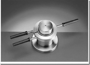
If there is no shaft damage, the inner race can be removed with an aluminum heating ring (Fig. 7.22). Remove the outer race and bearings, and wipe the inner ring clean. The heating ring is heated to around 500 O F, then clamped around the inner race. The race will loosen enough for removal.
FIGURE 7.22 The aluminum heating ling for removing the inner race of a ball bearing. SKF USA Inc.
Bearing Installation
One of the most important requirements for bearing installation is cleanliness. This includes tools, the motor components, and anything that has contact with the bearing.
Small bearings can be installed with a tube that fits the bearing’s inner race, and a soft hammer.
A hydraulic bearing press can be used for larger bearings. Pressure has to be uniformly applied to the bearing’s inner race only.
Heating is a popular method of bearing installation. Never use an open flame. The bearing should be heated uniformly and slowly. If the inner race is heated too fast, its rapid expansion will damage the bearing’s components, resulting in a noisy bearing.
Overheating is a major concern when any heat method is used to install bearings. The bearing should not be heated over 230 O F.
A properly heated bearing should be pushed in place on the shaft without stopping. The inner race will shrink and stick to this spot. If it isn’t in place, it will have to be pressed the rest of the way. When a bearing is installed using heat, it will shrink axially a minute amount. Rarely would this be a concern in an electric motor.
Hot oil is a good way to heat a bearing, if done properly. It uniformly heats the bearing, and protects it from rust for a short time.
The oil must be clean and should have a flash point above 480 O F, to reduce fire hazard. Also, care must be taken not to overheat the oil because of possible acid buildup.
The hot oil method works best with open bearings that are greased after installation. If the bearing is shielded, oil may dilute the grease.
A heating cabinet is a good method of heating a bearing. The bearing can be kept at the proper temperature in a clean environment for as long as needed using this method.
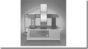
Figure 7.23 shows an automatic induction bearing heater. This unit goes through a number of important steps. A magnetized temperature sensor is placed on the bearing’s inner race. Power is automatically applied intermittently, allowing the heat to migrate to the outer race, which uniformly heats the entire bearing. Once the right temperature is reached, the bearing is demagnetized. Some types of induction heaters don’t magnetize the bearing.
The problem with most heating methods is the time and attention involved.
FIGURE 7.23 An automatic induction bearing heater. SKF USA Inc.
Identifying Bearing Breakdown Causes
If a motor has frequent bearing failure and the cause isn’t obvious, an effort should be made to discover the cause.
The best time to identify the cause of failure is when the bearing begins to get noisy. Mark the bearing’s outer race, the housing, the inner race, and the shaft (for reference) while disassembling the motor. This provides a reference point—that is, direction of belt load pull. The bearing can now be broken open to determine the cause of its failure. Some bearing companies provide pictures of failed bearings and identify reasons for their failure.
Bearing Current
Signs of current-caused bearing failure include uniform fluting pits across the inner and/or outer race and inline pits evenly spaced on the balls (Fig. 7.24).
When a voltage potential exists between the shaft and the stator, the current path is through the bearings. The voltage is usually low, and the lubrication between the bearing components has resistance that stops current flow.
There are times, however, when there is metal-to-metal contact. Current flows at this time between the races and the balls, forming a circuit between the shaft and stator.
FIGURE 7.24 The marking found in an electñc current—caused bearing failure. SKF USA Inc.
There is no damage to the bearing when current flows through it. (Damage occurs when the circuit is broken.) An arc forms between components at this time. (The same kind of arcing occurs when switch contacts open, and break a current-carrying circuit.) Some of the metal vaporizes, leaving pits. Eventually axial lines (fluting) form across the races.
Pits form in the balls, the bearing becomes noisy, and it soon fails.
Bearing current breakdown was a rare problem in the past. Variablefrequency drives are linked to an increase in this problem.
Attempts at solving this problem include using current-conducting grease; insulating the bearing from the housing; grounding brushes from shaft to stator; coating the outer race of the bearing with a hard, highresistance material; and using ceramic balls.
Conductive grease is one of the least successful. The grease has to maintain a conductive path large enough for all the current to flow between the shaft and the end bracket. The active grease is very thin—between the balls and races. Supplying enough grease to ensure good conduction would cause the grease to churn and overheat.
Insulating between the bearing and housing can lower the mechanical strength of a motor.
A grounding brush has been used, with varying results. It must be made of a very low-resistance material (with a high metal content for conducting the low-voltage-driven current). The wear factor between a high-metalcontent brush and shaft will be high. A small amount of resistance between the brush and shaft sends current through the bearing, which is a parallel circuit.
A bearing with its outer race coated with hard insulation works well. Such bearings are interchangeable with standard-size bearings and require no alteration of the motor housing. Bearings with ceramic balls also work well.
In extreme cases of bearing current, a combination of a grounding brush and coated bearings can be used. The grounding brush will conduct highervoltage-driven current that can bypass the bearing’s coating. The bearing’s coating will stop lower-voltage-driven current that the brush can’t conduct. The best solution is to eliminate the destructive voltage.
Bearing current problems occur in DC motors when their stator field is grounded, or when the power supply is grounded. Bearing current is also a problem with DC motors that are mounted on an electrically common machine, such as a locomotive.
Specialized Bearing Tools
There are many specialized tools for bearing handling. Proper use of them will prevent damage to the bearings, shaft, and outer housing. There are many cases of early bearing failure linked to faulty installation procedures.
Training courses offered by bearing companies are highly recommended. The courses teach correct procedures with specialized tools and timesaving methods.
Bearing pullers are available in many variations. Mechanical pullers for small to medium-sized bearings have two or three jaws for gripping the outer ring of the bearing (Fig. 7.25).
Hydraulic-powered tools are used for larger bearing removal and installation. A hydraulic press is also used for removal and installation.
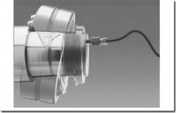
Oil injection is used for bearing removal. The shaft is modified as shown in Fig. 7.26. Oil is forced between the bearing’s inner race and the shaft as the bearing is pulled off.
Hydraulic nuts are a tool used to mount bearings. Roller bearings can be mounted precisely on a tapered shaft, using this tool. This type of bearing must be mounted precisely for maximum life.
FIGURE 7.25 One of many types of bearing pullers. Industrial Pulley Puller.
FIGURE 7.26 The oil injection method of bearing removal. SKF USA Inc.


![clip_image002[5] clip_image002[5]](http://machineryequipmentonline.com/electric-equipment/wp-content/uploads/2017/05/clip_image0025_thumb2.jpg)
![clip_image004[5] clip_image004[5]](http://machineryequipmentonline.com/electric-equipment/wp-content/uploads/2017/05/clip_image0045_thumb1.jpg)
