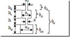
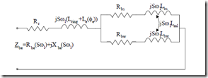
In some applications, very high starting torque–Tstart/Trated ≥ 2.0–is required. In such cases, a double cage is used. It has been proved that it behaves like a deep bar cage, but it produces even higher starting torque at lower starting current. For the case when skin effect can be neglected in both cages, let us consider a double cage as configured in Figure 9.18. [8]
Figure 9.18 Double cage rectangular-shape geometry a.) and equivalent circuit b.)
The equivalent single bar circuit is given in Figure 9.18b. For the common ring of the two cages
Rr = Rring, Rbs = Rbs upper bar, Rbw = Rbw lower bar (9.49) For separate rings
Rr = 0, Rbs = Rbs + Rerings, Rbw = Rbw + Reringw (9.50)
The ring segments are included into the bar resistance after approximate reduction as shown in Chapter 6. The value of Lring is the common ring inductance or is zero for separate rings. Also for both cases, Le(Φe) refers to the slot neck flux.
Le (Φe )= µ0lstack ha44 (9.51)
We may add into Le the differential leakage inductance of the rotor. The start (upper) and work (lower) cage inductances Lbs and Lbw include the end ring inductances only for separate rings. Otherwise, the bar inductances are
Lbs = µ0lstack 3hass
Lbw = µ0lstack 3haww + ha + hass (9.52) There is also a flux common to the two cages represented by the flux in the starting cage. [3]
Lml = µ0lstack 2hass (9.53)
In general, Lml is neglected though it is not a problem to consider in solving the equivalent circuit in Figure 9.18. It is evident (Figure 9.18a) that the starting (upper) cage has a large resistance (Rbs) and a small slot leakage inductance Lbs, while for the working cage the opposite is true.
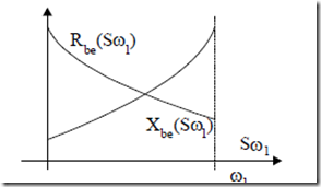
Consequently, at high slip frequency, the rotor current resides mainly in the upper (starting) cage while, at low slip frequency, the current flows mainly into the working (lower) cage. Thus both Rbe and Xbe vary with slip frequency as they do in a deep bar single cage (Figure 9.19).
Figure 9.19 Equivalent parameters of double cage versus slip frequency
LEAKAGE FLUX PATH SATURATION–A SIMPLIFIED APPROACH
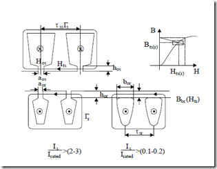
Leakage flux path saturation occurs mainly in the slot necks zone for semiclosed slots for currents above 2 to 3 times rated current or in the rotor slot iron bridges for closed slots even well below the rated current (Figure 9.20).
Consequently,
a ‘os = aos + (τss µ−saos )µ0; τss = πNDsi
a ‘or aor + sr µraor )µ0; τsr = π(DNi −s 2g) (9.54) (τ −
= a ‘or = bµorbrµb
The slot neck geometrical permeances will be changed to: a′os/hos, a′or/hor, or a′or/hor dependent on stator (rotor) current.
Figure 9.20 Leakage flux path saturation conditions
With ns the number of turns (conductors) per slot, and Is and Ib the stator and rotor currents, the Ampere’s law on Γs, Γr trajectories in Figure 9.20 yields
Hts (τss − aos )+ H aos os ≈ n Is s 2; µsHts = Bts = µ0Hos
![]() Htr (τsr − aor )+ H aor or ≈ Ib 2; µrHtr = Btr = µ0Hor (9.55)
Htr (τsr − aor )+ H aor or ≈ Ib 2; µrHtr = Btr = µ0Hor (9.55)
H btr or = Ib 2; µbr = HBtbtb
The relationship between the equivalent rotor current Ir′ (reduced to the stator) and Ib is (Chapter 8)
Ib = I ‘r 6p1qnNsrKw1 = I ‘n Kr s w1 NNsr (9.56)
Ns–number of stator slots; Kw1–stator winding factor.
When the stator and rotor currents Is and Ir′ are assigned pertinent values, iteratively, using the lamination magnetization curves, Equations (9.55) may be solved (Figure 9.20) to find the iron permeabilities of teeth tops or of closed rotor slot bridges. Finally, from (9.54), the corrected slot openings are found. With these values, the stator and rotor parameters (resistances and leakage inductances) as influenced by the skin effect (in the slot body zone) and by the leakage saturation (in the slot neck permeance) are recalculated. Continuing with these values, from the equivalent circuit, new values of stator and rotor currents Is, Ir′ are calculated for given stator and voltage, frequency and slip. The iteration cycles continue until sufficient convergence is obtained for stator current.
Example 9.4. An induction motor has semiclosed rectangular slots whose geometry is shown in Figure 9.21.
The current density design for rated current is jCo = 6.5 A/mm2 and the slot fill factor Kfill = 0.45. The starting current is 6 times rated current. Let us calculate the slot leakage specific permeance at rated current and at start.
Solution
The slot mmf nsIs is obtained from
n Is s = (h a Ks s ) fill Coj =10 35⋅ ⋅0.45⋅6.5 =1023.75Ampereturns
Making use of (9.54),
![]() Hts (18− 4.5)+ Bµts0 4.5 ⋅10−3 =1023.75 2
Hts (18− 4.5)+ Bµts0 4.5 ⋅10−3 =1023.75 2
It is very clear that for rated current Bts < 0.4029, so the tooth heads are not saturated. In (9.54), aos′ = aos and the slot specific geometrical permeance λs is
For the starting conditions,
![]() Htstart (18− 4.5)⋅10−3 + Bµ0ts 4.5 ⋅10−3 = 6142.5 2
Htstart (18− 4.5)⋅10−3 + Bµ0ts 4.5 ⋅10−3 = 6142.5 2
Btstart = 2.41− Htstart 3µ0
Now we need the lamination magnetization curve. If we do so we get Btstart
≈ 2.16T, Htstart ≈ 70,000 A/m. The iron permeability µs is
![]() µs = Btstart µ0−1 = 70000⋅2.1.16256 10⋅ −6 = 24.56
µs = Btstart µ0−1 = 70000⋅2.1.16256 10⋅ −6 = 24.56
µ0 Htstart
Consequently, aos ‘= aos + (τ −s µsaos )µ =0 4.5+ (1824−.564.5) = 5.05mm
The slot geometric specific permeance is, at start,
The leakage saturation of tooth heads at start is not very important in our case. In reality, it could be more important for semiclosed stator (rotor) slots.
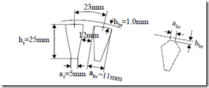
Example 9.5. Let us consider a rotor bar with the geometry of Figure 9.21. The bar current at rated current density jAlr = 6.0 A/mm2 is
Figure 9.22. Closed rotor slots
Calculate the rotor bridge flux density for 10%, 20%, 30%, 50%, 100% of rated current and the corresponding slot geometrical specific permeance.
Solution
Let us first introduce a typical magnetization curve.
|
B(T) |
0.05 |
0.1 |
0.15 |
0.2 |
0.25 |
0.3 |
0.35 |
0.4 |
0.45 |
0.5 |
|
H(A/m) |
22.8 |
35 |
45 |
49 |
57 |
65 |
70 |
76 |
83 |
90 |
|
B(T) |
0.55 |
0.6 |
0.65 |
0.7 |
0.75 |
0.8 |
0.85 |
0.9 |
0.95 |
1 |
|
H(A/m) |
98 |
106 |
115 |
124 |
135 |
148 |
162 |
177 |
198 |
220 |
|
B(T) |
1.05 |
1.1 |
1.15 |
1.2 |
1.25 |
1.3 |
1.35 |
1.4 |
1.45 |
1.5 |
|
H(A/m) |
237 |
273 |
310 |
356 |
417 |
482 |
585 |
760 |
1050 |
1340 |
|
B(T) |
1.55 |
1.6 |
1.65 |
1.7 |
1.75 |
1.8 |
1.85 |
1.9 |
1.95 |
2.0 |
|
H(A/m) |
1760 |
2460 |
3460 |
4800 |
6160 |
8270 11170 15220 22000 34000 |
Neglecting the tooth top saturation and including only the bridge zone, the Ampere’s law yields
![]() = I ;b H br = aIbrb ; a br =11mm
= I ;b H br = aIbrb ; a br =11mm
H br a br
For various levels of bar current, Hbr and Bbr become
|
Ib (A) |
120 |
240 |
360 |
600 |
1200 |
|
Hbr |
10909 |
21818 |
32727 |
54545 |
109090 |
|
Bbr |
1.84 |
1.95 |
1.98 |
2.1 |
2.2 |
|
µ µrel = µbr0 |
134.28 |
71.16 |
48.165 |
30.653 |
16.056 |
|
aor ‘= µarelbr (mm) |
0.0819 |
0.1546 |
0.2284 |
0.3588 |
0.6851 |
|
λslot = 3 |
14.293 |
75.1 |
5.42 |
3.8287 |
2.5013 |
Note that at low current levels the slot geometrical specific permeance is unusually high. This is because the iron bridge is long (abr = 11mm); so Hbr is small at small currents.
Also, the iron bridge is 1mm thick in our case, while 0.5 to 0.6 mm would produce better results (lower λslot). The slot height is quite large (hr = 25 mm) so significant skin effect is expected at high slips. We investigated here only the currents below the rated one so Sf1 < 3 Hz in general. Should the skin effect occur, it would have reduced the first term in λslot (slot body specific geometrical permeance) by the factor Kx.
As a conclusion to this numerical example, we may infer that a thinner bridge with a smaller length would saturate sooner (at smaller currents below the rated one), producing finally a lower slot leakage permeance λslot. The advantages of closed slots are related to lower stray load losses and lower noise.
