Electric copper conductors are used to produce the stator three (two) phase windings. The same is true for wound rotor windings.
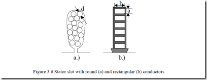
Electrical copper has a high purity and is fabricated by an involved electrolysis process. The purity is well above 99%. The cross-section of copper conductors (wires) to be introduced in stator slots is either circular or rectangular (Figure 3.6). The electrical resistivity of magnetic wire (electric conductor) ρCo = (1.65-1.8) × 10-8Ωm at 200C and varies with temperature as ρCo( ) (T = ρCo )200 [1+ (T −20)/ 273] (3.19)
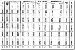
Round magnetic wires come in standardized gauges up to a bare copper diameter of about 2.5mm (3mm) (or 0.12inch), in general (Tables 3.4 and 3.5). The total cross-section Acon of the coil conductor depends on the rated phase current I1n and the design current density Jcon.
Acon = I1n / Jcon (3.20)
The design current density varies between 3.5 and 15 A/mm2 depending on the cooling system, service duty cycle, and the targeted efficiency of the IM. High efficiency IMs are characterized by lower current density (3.5 to 6 A/mm2). If the Acon in (3.19) is larger than the cross section of the largest round wire gauge available, a few conductors of lower diameter are connected in parallel and wound together. Up to 6 to 8 elementary conductors may be connected together.
Table 3.4. Round magnetic wire gauges in inches
In the near future, better silicon 0.5 mm (0.35 mm) thick steel laminations with nonoriented grain seem to remain the basic soft magnetic materials for IM fabrication. For high speed (frequency above 300 Hz) thinner laminations are to be used. The insulation coating layer of each lamination is getting thinner and thinner to retain a good stacking factor (above 85%).
3.4. ELECTRICAL CONDUCTORS
Electric copper conductors are used to produce the stator three (two) phase windings. The same is true for wound rotor windings.
Electrical copper has a high purity and is fabricated by an involved electrolysis process. The purity is well above 99%. The cross-section of copper conductors (wires) to be introduced in stator slots is either circular or rectangular (Figure 3.6). The electrical resistivity of magnetic wire (electric conductor) ρCo = (1.65-1.8) × 10-8Ωm at 200C and varies with temperature as
ρCo( ) (T = ρCo )200 [1+ (T −20)/ 273] (3.19)
Figure 3.6 Stator slot with round (a) and rectangular (b) conductors
Round magnetic wires come in standardized gauges up to a bare copper diameter of about 2.5mm (3mm) (or 0.12inch), in general (Tables 3.4 and 3.5). The total cross-section Acon of the coil conductor depends on the rated phase current I1n and the design current density Jcon.
Acon = I1n / Jcon (3.20)
The design current density varies between 3.5 and 15 A/mm2 depending on the cooling system, service duty cycle, and the targeted efficiency of the IM. High efficiency IMs are characterized by lower current density (3.5 to 6 A/mm2). If the Acon in (3.19) is larger than the cross section of the largest round wire gauge available, a few conductors of lower diameter are connected in parallel and wound together. Up to 6 to 8 elementary conductors may be connected together.
Table 3.4. Round magnetic wire gauges in inches
Table 3.5. Typical round magnetic wire gauges in mm
|
Rated diameter [mm] |
Insulated wire diameter [mm] |
|
0.3 |
0.327 |
|
0.32 |
0.348 |
|
0.33 |
0.359 |
|
0.35 |
0.3795 |
|
0.38 |
0.4105 |
|
0.40 |
0.4315 |
|
0.42 |
0.4625 |
|
0.45 |
0.4835 |
|
0.48 |
0.515 |
|
0.50 |
0.536 |
|
0.53 |
0.567 |
|
0.55 |
0.5875 |
|
0.58 |
0.6185 |
|
0.60 |
0.639 |
|
0.63 |
0.6705 |
|
0.65 |
0.691 |
|
0.67 |
0.7145 |
|
0.70 |
0.742 |
|
0.71 |
0.7525 |
|
0.75 |
0.7949 |
|
0.80 |
0.8455 |
|
0.85 |
0.897 |
|
0.90 |
0.948 |
|
0.95 |
1.0 |
|
1.00 |
1.051 |
|
1.05 |
1.102 |
|
1.10 |
1.153 |
|
1.12 |
1.173 |
|
1.15 |
1.2035 |
|
1.18 |
1.2345 |
|
1.20 |
1.305 |
|
1.25 |
1.325 |
|
1.30 |
1.356 |
|
1.32 |
1.3765 |
|
1.35 |
1.407 |
|
1.40 |
1.4575 |
|
1.45 |
1.508 |
|
1.50 |
1.559 |
If Acon is larger than 30 to 40 mm2 (that is 6 to 8, 2.5 mm diameter wires in parallel), rectangular conductors are recommended.
In many countries rectangular conductor cross sections are also standardized. In some cases small cross sections such as (0.8 to 2)⋅2 mm × mm or (0.8 to 6) × 6 mm × mm.
In general the rectangular conductor height a is kept low (a < 3.55 mm) to reduce the skin effect; that is, to keep the a.c. resistance low. A large cross section area of 3.55 × 50 mm × mm would be typical for large power IMs.
The rotor cage is generally made of aluminum: die-casted aluminum in low power IMs (up to 300 kW or so) or of aluminum bars attached through brazing or welding processes to end rings.
Fabricated rotor cages are made of aluminum or copper alloys and of brass (the upper cage of a double cage) for powers above 300 kW in general. The casting process of aluminum uses the rotor lamination stack as a partial mold because the melting point of silicon steel is much higher than that of aluminum.
The electrical resistivity of aluminium ρAl≅ (2.7-3.0)10-8 Ωm and varies with temperature as shown in (3.19).
Although the rotor cage bars are insulated from the magnetic core, most of the current flows through the cage bars as their resistivity is more than 20 to 30 times smaller than that of the laminated core.
Insulated cage bars would be ideal, but this would severely limit the rotor temperature unless a special high temperature (high cost) insulation coating is used.
3.5. INSULATION MATERIALS
The primary purpose of stator insulation is to withstand turn-to-turn, phaseto-phase and phase-to-ground voltage such that to direct the stator phase currents through the desired paths of stator windings.
Insulation serves a similar purpose in phase-wound rotors whose phase leads are connected to insulated copper rings and then through brushes to stationary devices (resistances or/and special power electronic converters). Insulation is required to withstand voltages associated to: brush rigging (if any) winding connections, winding leads and auxiliaries such as temperature probes and bearings (especially for PWM inverter drives).
The stator laminations are insulated from each other by special coatings (0.013 mm thick) to reduce eddy current core losses.
In standard IMs the rotor (slip) frequency is rather small and thus interlamination insulation may not be necessary, unless the IM is to work for prolonged intervals at large slip values.
For all wound-rotor motors, the rotor laminations are insulated from each other. The bearing sitting is insulated from the stator to reduce the bearing (shaft) voltage (current), especially for large power IMs whose stator laminations are
made of a few segments thus allowing a notable a.c. axial flux linkage. This way premature bearing damage may be prevented and even so in PWM inverter fed IMs, where additional common voltage mode superhigh frequency capacitor currents through the bearings occur (Chapter 21).
Stator winding insulation systems may be divided in two types related to power and voltage level.
• Random-wound conductor IMs-with small and round conductors
• Form-wound conductor IMs-with relatively large rectangular conductors
Insulation systems for IMs are characterized by voltage and temperature requirements. The IM insulation has to withstand the expected operating voltages between conductors, (phase) conductors and ground, and phase to phase.
The American National Standards Institute (ANSI) specifies that the insulation test voltage shall be twice the rated voltage plus 100 V applied to the stator winding for 1 minute.
The heat produced by the winding currents and the core losses causes hotspot temperatures that have to be limited in accordance to the thermal capability of the organic (resin) insulation used in the machine, and to its chemical stability and capability to prevent conductor to conductor, conductor to ground short-circuits during IM operation.
There is continuous, but slow deterioration of the organic (resin) insulation by internal chemical reaction, contamination, and chemical interactions. Thermal degradation develops cracks in the enamel, varnish, or resin, reducing the dielectric strength of insulation.
Insulation materials for electric machines have been organized in stable temperature classes at which they are able to perform satisfactorily for the expected service lifetime.
The temperature classes are (again)
Class A: 105°C Class F: 155°C
Class B: 130°C Class G: 180°C
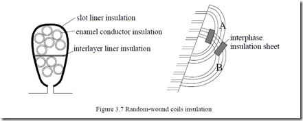
The main insulation components for the random-wound coil windings are the enamel insulation on the wire, the insulation between coils and ground/slot walls-slot liner insulation, and between phases (Figure 3.7).
The connections between the coils of a phase and the leads to the terminal box have to be insulated. Also the binding cord used to tie down endwindings to reduce their vibration is made of insulation materials.
Random-wound IMs are built for voltages below 1 kV. The moderate currents involved can be handled by wound conductors (eventually a few in parallel) where enamel insulation is the critical component. To apply the enamel, the wire is passed through a solution of polymerizable resin and into the high-curing temperature tower where it turns into a thin, solid, and flexible coating.
3.5.1. Random-wound IM insulation
Several passes are required for the desired thickness (0.025 mm thick or so). There are dedicated standards that mention the tests on enamel conductors (ASTMD-1676; ASTM standards part 39 electric insulation-test methods: solids and solidifying liquids should be considered for the scope.
Enamel wire, stretched and scraped when the coils are introduced into the slots, should survive this operation without notable damage to the enamel. Some insulation varnish is applied over the enamel wire after the stator winding is completed. The varnish provides additional enamel protection against moisture, dirt, and chemical contamination and also provides mechanical support for the windings.
Slot and phase-to-phase insulation for class A temperatures is a somewhat flexible sheet material (such as cellulose paper), 0.125 to 0.25 mm thick, or a polyester film. In some cases fused resin coatings are applied to stator slot walls by electrostatic attraction of a polymerizable resin powder. The stator is heated to fuse and cure the resin to a smooth coating.
For high temperature IMs (class F, H), glass cloth mica paper or asbestos treated with special varnishes are used for slot and phase-to-phase insulation. Varnishes may interact with the emanel to reduce the thermal stability. Enamels and varnishes are tested separately according to ASTM (D2307, D1973, D3145) and IEC standards and together.
Model motor insulation systems (motorettes) are tested according to IEEE standards for small motors.
All these insulation accelerated life tests involve the ageing of insulation test specimens until they fail at temperatures higher than the operating temperature of the respective motor. The logarithms of the accelerated ageing times are then graphed against their reciprocal Kelvin test temperatures (Arhenius graph). The graph is then extrapolated to the planed (reduced) temperature to predict the actual lifetime of insulation.
3.5.2. Form-wound windings
Form-wound windings are employed in high power IMs. The slots are rectangular and so are the conductors. The slot filling factor increases due to this combination.
The insulation of the coil conductors (turns) is applied before inserting the coils in slots. The coils are vacuum also impregnated outside the machine. The slot insulation is made of resin-bonded mica applied as a wrapper or tape with a fibrous sheet for support (in high voltage IMs above 1 to 2 kV).
Vacuum impregnation is done with polymerizable resins which are then cured to solids by heating. During the cure, the conductors may be constrained to size to enter the slot as the epoxy-type resins are sufficiently elastic for the scope.
Voltage, through partial discharges, may cause insulation failure in higher voltage IMs. Incorporating mica in the major insulation schemes solves this problem to a large degree.
A conducting paint may be applied over the slot portion of the coils to fill the space between the insulated preformed coil and slot wall, to avoid partial discharges. Lower and medium voltage coil insulation is measured in accelerated higher temperature tests (IEEE standard 275) by using the model system called formette. Formette testing is similar to motorette testing for random-wound IMs [15].
Diagnostic nondestructive tests to check the integrity and capability of large IM insulation are also standardized [15 – 17].


