Power
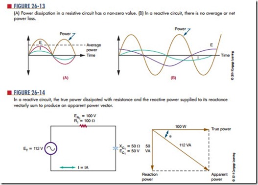
The power consumption of a purely resistive AC circuit is easy to determine. Calculate the product of the rms current and rms voltage to obtain the aver- age power. Figure 26-13A shows a graphical method in which instantaneous power consumption may be calculated by plotting current and voltage on the same axes and then performing successive multiplications to plot the power curve.
The same principle may be applied to the reactive circuit (b). Remember that a circuit containing just pure inductance shows current lagging voltage by 90°. Plotting the power curve for this circuit yields an alternating waveform that is centered on 0. The net power consumption of an inductive circuit is low.
During the positive portion of the waveform, the inductor takes energy and stores it in the form of a magnetic field. During the negative portion of the waveform, the field collapses and the coil returns energy to the circuit. A similar situation occurs with pure capacitance, except the capacitor stores energy as an electrostatic field and the voltage current phase relationship is reversed.
As resistance is introduced to a circuit, the phase angle becomes less than 90° and the power curve shifts to a more positive value, showing that the circuit is taking more energy than it is returning. How- ever, the capacitive or inductive part of the circuit still stores and releases energy and consumes no power. The power loss is due entirely to the resistance. Remember, only the resistive part of the circuit consumes power.
Figure 26-14 shows a capacitive circuit. Using the Pythagorean theorem, the resistance of 100 ohms and the capacitance reactance of 50 ohms gives a combined impedance (Z) of approximately 112 ohms, as follows:
Using Ohm’s law, this would allow a current of ap- proximately 1 amp to flow in the circuit. The voltage drop across the resistor would be 100 volts, so the true power dissipated by the resistor would be approxi- mately 100 watts.
The capacitive part of the circuit consumes no power, yet multiplying the source voltage by circuit current yields an answer of 112 watts. The difference is accounted for by the difference in phases between the various voltages. As opposed to true power, the figure obtained by multiplying the source voltage and cur- rent is known as apparent power, and it is specified as 112 VA, or 112 volt-amperes. The true power of the circuit can never be greater than the apparent power. The ratio of true power in watts to apparent power in volt-amps is called the power factor.
Vector diagrams may be used to analyze the power factor. If the phase angle of the circuit is known, the power factor may be calculated by taking the cosine of the angle. In the circuit shown in Figure 26-14, it is the same as the ratio of ER to source voltage. Several methods are used to obtain the power factor based on the data available. In a pure resistive circuit, the true power is the same as the apparent power, so the power factor is 1. In a pure inductive or capacitive circuit, the true power is 0, no matter what the apparent power is, so the power factor is 0. Power factor is an important consideration in heavy industrial power distribution where the cables must be capable of handling the apparent power load.
Questions
1. What is the net power consumption of an in- ductive circuit? Why?
2. What is the relationship between true power and apparent power?
3. Define power factor.
4. Calculate the apparent power for the circuit shown in Figure 26-15.
5. Why is the power factor important to industry?


