The a.c. windings for induction motors are usually built in one or two layers.
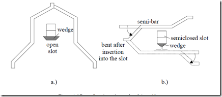
The basic structural element is represented by coils. We already pointed out (Figure 4.2) that there may be lap and wave coils. This is the case for single turn (bar) coils. Such coils are made of continuous bars (Figure 4.6a) for open slots or from semibars bent and welded together after insertion in semiclosed slots (figure 4.6b).
Figure 4.6 Bar coils: a.) continuous bar, b.) semi bar
These are preformed coils generally suitable for large machines.
Continuous bar coils may also be made from a few elementary conductors in parallel to reduce the skin effect to acceptable levels.
On the other hand, round-wire, mechanically flexible coils forced into semiclosed slots are typical for low power induction machines.
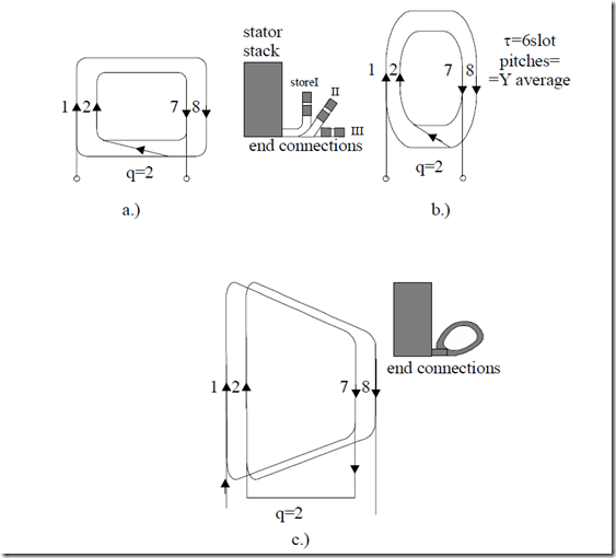
Such coils may have various shapes such as shown in Figure 4.7.
A few remarks are in order.
• Wire-coils for single layer windings, typical for low power induction motors (kW range and 2p1 = 2pole) have in general wave-shape;
• Coils for single layer windings are always full pitch as an average
• The coils may be concentrated or identical
• The main concern should be to produce equal resistance and leakage inductance per phase
• From this point of view, rounded concentrated or chain-shape identical coils are to be preferred for single layer windings
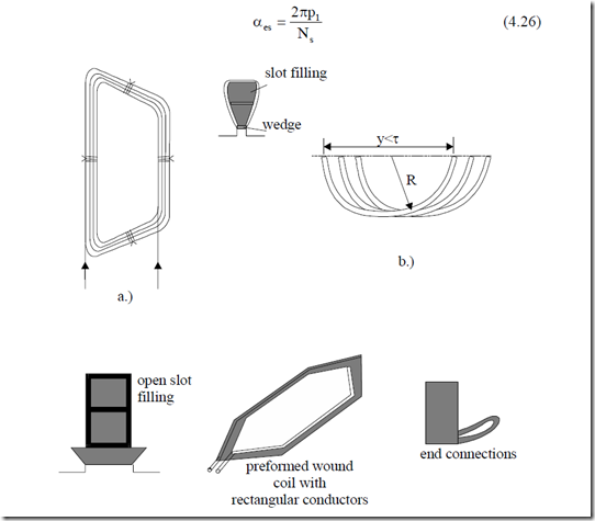
Double-layer winding coils for low power induction machines are of trapezoidal shape and round shape wire type (Figure 4.8a, b).
For large power motors, preformed multibar (rectangular wire) (Figure4.8c) or unibar coils (Figure 4.6) are used.
Now to return to the basic rules for a.c. windings design let us first remember that they may be integer q or fractional q (q = a+b/c) windings with the total number of slots Ns = 2p1qm. The number of slots per pole could be only an integer. Consequently, for a fractional q, the latter is different and integer for a phase under different poles. Only the average q is fractional.
Single-layer windings are built only with an integer q.
As one coil sides occupy 2 slots, it means that Ns/2m = an integer (m– number of phases; m = 3 in our case) for single-layer windings. The number of inward current coil sides is evidently equal to the number of outward current coil sides.
Fortwo-layer windings the allocation of slots per phase is performed in one (say, upper) layer. The second layer is occupied “automatically” by observing the coil pitch whose first side is in one layer and the second one in the second layer. In this case it is sufficient to have Ns/m = an integer.
Figure 4.7 Full pitch coil groups/phase/pole−for q = 2−for single layer a.c. windings:
a.) with concentrated rectangular shape coils and 2 (3) store end connections;
b.) with concentrated rounded coils; c.) with chain shape coils.
A pure traveling stator mmf (4.13), with an open rotor winding and a constant airgap (slot opening effects are neglected), when the stator and iron core permeability is infinite, will produce a no-load ideal flux density in the airgap as
Bg10(x,t)= µ0 1gF m cosπτ x − ω1t (4.25) according to Biot – Savart law.
This flux density will self-induce sinusoidal emfs in the stator windings.
The emf induced in coil sides placed in neighboring slots are thus phase shifted by αes
αes = 2Nπps 1 (4.26)
Figure 4.8 Typical coils for two-layer a.c. windings:
a. trapezoidal flexible coil (round wire);
b. rounded flexible coil (rounded wire);
c. preformed wound coil (of rectangular wire) for open slots.
The number of slots with emfs in phase, t, is
t = greatest common divisor (Ns,p1) = g.c.d. (Ns,p1) ≤ p1 (4.27) Thus the number of slots with emfs of distinct phase is Ns/t. Finally the phase shift between neighboring distinct slot emfs αet is
αet =2Nπst (4.28)
If αes = αet, that is t = p1, the counting of slots in the emf phasor star diagram is the real one in the machine.
Now consider the case of a single winding with Ns = 24, 2p1 = 4. In this case
αes = 2Nπps 1 = 2π⋅242 = π6 (4.29)
t = g.c.d. (Ns,p1) = g.c.d.(24,2) = 2 = p1 (4.30)
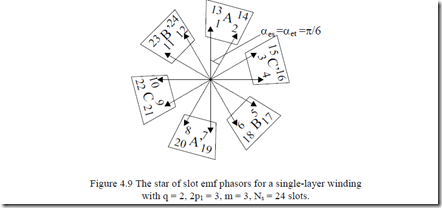
So the number of distinct emfs in slots is Ns/t = 24/2 = 12 and their phase shift αet = αes = π/6. So their counting (order) is the natural one (Figure. 4.9).
The allocation of slots to phases to produce a symmetric winding is to be done as follows for single-layer windings
• Built up the slot emf phasor star based on calculating αet, αes, Ns/t distinct arrows counting them in natural order after αes.
• Choose randomly Ns/2m successive arrows to make up the inward current slots of phase A (Figure 4.9).
• The outward current arrows of phase A are phase shifted by π radians with respect to the inward current ones.
• By skipping Ns/2m slots from phase A, we find the slots of phase B.
• Skipping further Ns/2m slots from phase B we find the slots of phase C.
double-layer windings
• Build up the slot emf phasor star as for single-layer windings.
• Choose Ns/m arrows for each phase and divide them into two groups (one for inward current sides and one for outward current sides) such that they are as opposite as possible.
• The same routine is repeated for the other phases providing a phase shift of 2π/3 radians between phases.
It is well understood that the above rules are also valid for the case of fractional q. Fractional q windings are built only in two-layers and small q, to reduce the order of first slot harmonic.
Placing the coils in slots
For single-layer, full pitch windings, the inward and outward side coil occupy entirely the allocated slots from left to right for each phase. There will be Ns/2m coils/phase.
The chorded coils of double-layer windings, with a pitch y (2τ/3 ≤ y <τ for integer q and single pole count windings) are placed from left to right for each phase, with one side in one layer and the other side in the second layer. They are connected observing the inward (A, B, C) and outward (A’, B’, C’) directions of currents in their sides.
Connecting the coils per phase
The Ns/2m coils per phase for single-layer windings and the Ns/m coils per phase for double-layer windings are connected in series (or series/parallel) such
that for the first layer the inward/outward directions are observed. With all coils/phase in series, we obtain a single current path (a = 1). We may obtain “a” current paths if the coils from 2p1/a poles are connected in series and, then, the “a ” chains in parallel.
Example 4.2.Let us design a single-layer winding with 2p1 = 2 poles, q = 4, m = 3 phases.
Solution
The angle αes (4.26), t (4.27), αet (4.28) are
t = g.c.d.(Ns, P1) = g.c.d.(24,1) = 1
Also the count of distinct arrows of slot emf star Ns/t = 24/1 = 24.
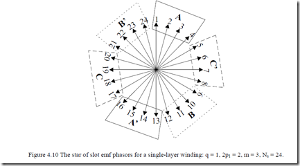
Consequently the number of arrows in the slot emf star is 24 and their order is the real (geometrical) one (1, 2, … 24)–Figure 4.10.
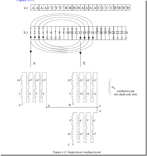
Making use of Figure 4.10, we may thus alocate the slots to phases as in Figure 4.11.
a.) slot/phase allocation; b.) rounded coils of phase A; c.) coils per phase
Example 4.3. Let us consider a double-layer three-phase winding with q = 3,
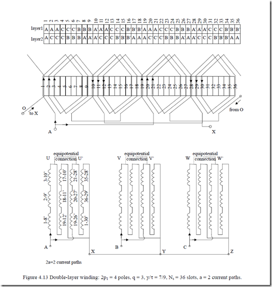
2p1 = 4, m = 3, (Ns = 2p1qm = 36 slots), chorded coils y/τ = 7/9 with a = 2 current paths.
Solution
Proceeding as explained above, we may calculate αes, t, αet:
t = g.c.d.(36,2) = 2
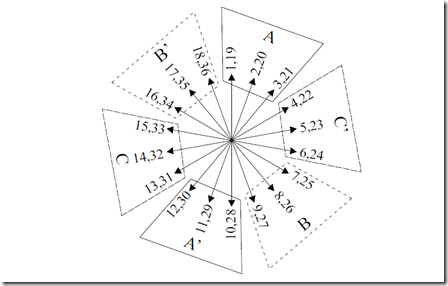
Figure 4.12 The star of slot emf phasors for a double-layer winding (one layer shown) with 2p1 = 4 poles,
q = 3 slots/pole/phase, m = 3, Ns = 36
There are 18 distinct arrows in the slot emf star as shown in Figure 4.12. The winding layout is shown in Figure 4.13. We should notice the second layer slot allocation lagging by τ – y = 9 – 7 = 2 slots, the first layer allocation. Phase A produces 4 fully symmetric poles. Also, the current paths are fully symmetric. Equipotential points of two current paths U – U’, V – V’, W – W’ could be connected to each other to handle circulating currents due to, say, rotor eccentricity.
Note that using wave coils is justified in single-bar coils to reduce the external leads to one by which the coils are connected to each other in series. Copper, labor, and space savings are the advantages of this solution.
