MICROPROCESSOR INSTRUCTION SET AND COMPUTER LANGUAGES

MICROPROCESSOR INSTRUCTION SET AND COMPUTER LANGUAGES

Microprocessors recognize and operate in binary numbers. However, each micro­processor has its own binary words, instructions, meanings, and language. The words are formed by combining a number of bits for a given machine. The word (or word length), as defined earlier, is the number of bits the microprocessor rec­ognizes and processes at a time. The word length ranges from 4 bits for small, microprocessor-based computers, to 32 bits for such large computers as the IBM ES 9000 series. Another term commonly used to express word length is byte. The ,byte is defined as a group of eight bits. For example, a l6-bit microprocessor has a word length equal to two bytes. The term "nibble," which stands for a group of four bits, is also found in popular computer magazines and books. (A byte has two nibbles.)

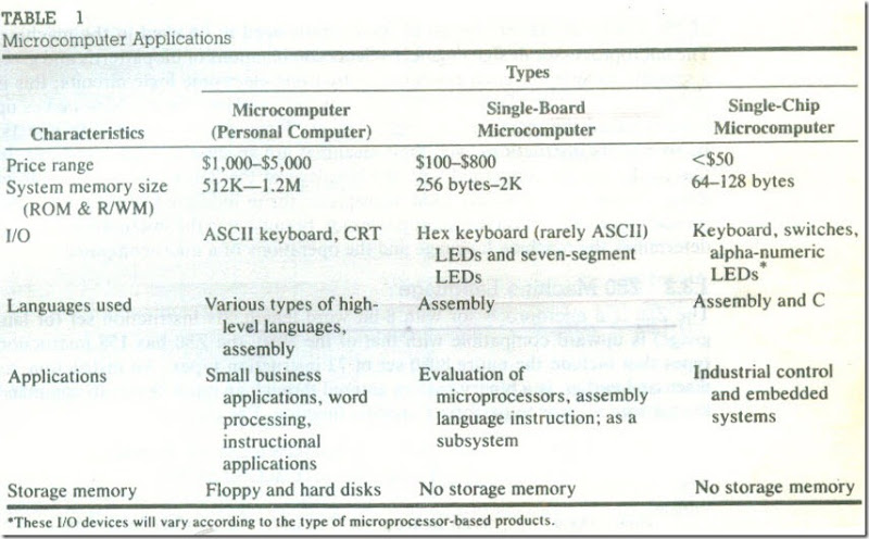
TABLE 1

Microcomputer Applications

MICROPROCESSOR INSTRUCTION SET AND COMPUTER LANGUAGES -17_03 

The instruction is defined as a complete task (such as Add) the microproces­sor can perform ; it can be made up of one or more words. Each machine has its own set of instructions based on the design of its CPU or its microprocessor. To be intelligible to the microprocessor, instructions must be written in binary lan­guage, also known as machine language. However, it is difficult for human beings to write programs in sets of Os and Is. Therefore, microprocessor manufacturers have devised English-like words to represent the binary instructions of a machine, and programmers can write programs using these words. These are called assem­bly language programs. Because an assembly language is specific to a given ma­chine programs written in assembly language are not transferable from one ma­chine to another. To circumvent this limitation, such general-purpose languages as BASIC, FORTRAN, PASCAL, and C have been devised so that a program written in these languages can be machine-independent. These languages are called high-level languages (HLL). This section deals with various aspects of these three types of languages: machine, assembly, and high-level. The machine and assembly languages are discussed in the context of the 280 microprocessor.

Machine Language

The number of bits in a word for a given machine is fixed, and words are formed through various ‘combinations of these bits. For example; a machine with a word length of eight bit scan have 756 (28) combinations of eight bits-thus a language of 256 words. However, not all of these words need to be used in the machine. The microprocessor design engineer selects combinations of bit patterns and gives a specific meaning to each combination by using electronic logic circuits; this is called an instruction .The set of instructions designed into the machine makes up what is called the machine language, a binary language composed of Os and Is. Its words, its instructions, and their meanings are specific to each computer. In this book, we are concerned with the language of the Z80 microprocessor from Zilog Corporation, a widely used microprocessor in industrial ·applications. The primary focus here is on the microprocessor, because it is the microprocessor that determines the machine language and the operations of a microcomputer.

Z80 Machine Language

The Z80 is a microprocessor with 8-bit word length .Its instruction set (or lan­guage) is upward compatible with that of the 8080; the Z80 has 158 instruction types that include the entire 8080 set of 72 instruction types. An instruction, as discussed earlier, is a binary pattern entered through an input device to command the microprocessor to perform a specific function. For example:

0011 1100           is an instruction that increments the number in the register called the accumulator by one.

1000 0000           is an instruction that adds the number in the reg­ister called B to the number in the accumulator, and keeps the sum in the accumulator.

The Z80 microprocessor has a variety of such bit patterns resulting in its 158 instruction types for performing; different operations, called the instruction set. The Z80 microprocessor also accepts data in 8-bit words as input from input de­vices, processes data according to the instructions written by the user, and sends out data in 8-bit words to output devices. This binary language with a predeter­mined instruction set is called the Z80 machine language.

However, it is tedious and conducive to error for human beings to recognize and write instructions in binary language. Therefore, for convenience, these in­structions are written in hexadecimal (or octal) code and entered into a single­ board microcomputer by using Hex keys.

For example, the binary instruction 0011 1100 (mentioned previously) is equivalent to 3C in hexadecimal. This instruction can be entered into a single ­board microcomputer system with Hex keyboard by pressing two keys: 3 and C. The monitor program of the system translates these keys into their equivalent binary pattern .

Z80 Assembly Language

Even though the instructions can be written in hexadecimal code, it is still not easy to understand such a program. Therefore, each manufacturer of micropro­cessors has devised a symbolic code for each instruction, called a mnemonic. (The word mnemonic is based on the Greek word related to memory aid.) The mne­monic for a particular instruction consists of letters that suggest the operation to be performed by that instruction.

For example, the binary code 001] 1100 (3C16 or 3CH (Hexadecimal numbers are shown with the subscript H in the text ) in hexadecimal) of the 280 microprocessor is represented by the mnemonic INC A:

INC  A                INC stands for increment, and A represents the accumulator. This symbol suggests the operation of incrementing the accumulator con­tent by one.

Similarly, the binary code 10000000 (8016 or 80H (Hexadecimal numbers are shown with the subscript H in the text ) is represented as follows:

ADD A, B          ADD stands for addition, and A and B represent the contents in the accumulator and register B, respectively. This symbol suggests the addition of the contents in register B and the accumulator.

Even though these symbols do not sp~ the complete operations, they suggest the significant portions. The complete description of each instruction must be supplied by the manufacturer. The complete set of Z80 mnemonics is called the Z80 instruction set, and a program written in these mnemonics is called an assembly language program. Again, the assembly language is specific to each microprocessor. For example, the Motorola 6809 microprocessor has an entirely different set of binary codes and mnemonics from that of the Z80. An assembly language program written for one microprocessor is not transferable to a com­puter with another microprocessor unless the two microprocessors are compatible in their machine codes.

The machine language and the assembly language are microprocessor­ specific, and both are considered low-level languages. The machine language is in binary, and the assembly language is in English-like words; however, the micro­processor understands only the binary. How, then, are the assembly language mnemonics entered into a microprocessor system and translated into binary code? In a microcomputer, the mnemonics are entered as ASCIl code (explained in the next section) using the keyboard as an input device, and the translation is per­formed by a program called an assembler. In a single-board microcomputer, the user translates mnemonics into Hex digits by looking up the code manually in the instruction set and enters them into the system through the Hex keyboard. This is called hand assembly.

Alphanumeric Codes

A computer is a binary machine; in order to communicate with the computer in alphabetic letters and decimal numbers. translation codes are necessary. The commonly used code is known as ASCII-American Standard Code for Infor­mation Interchange. It is a 7-bit code with 128 (27) combinations, and each combination from OOH to 7FH is assigned to either a letter, a decimal number, a symbol, or a machine command (see Appendix C). For example, hexadecimal 30H to 39H represent 0 to 9, decimal digits, 41H to 5AH represent capital letters A through Z, 20H to 2FH represent various symbols, and the initial codes OOH to I FH represent such machine commands as carriage return and line feed. Devices that use ASCII characters include ASCII terminals, teletype machines (TTY), and printers. When the key 9 is pressed on an ASCII terminal, the computer receives 39H in binary, and the system program translates ASCII characters into appropriate bi­nary or BCD numbers.

Another code, called EBCDIC (Extended Binary Coded Decimal Inter­change Code) is widely used in IBM computers (except in lBM Personal Com­puters or microcomputers). This is an 8-bit code represent in 256 combinations; however, several combinations are not used.

Writing and Executing an Assembly Language Program

As explained earlier, a program is a set of logically related instructions written in a specific sequence to accomplish a task. To write and execute an assembly lan­guage program manually on a single-board computer, with a Hex keyboard for input and LEOs (or seven-segment LEOs) for output, the following steps are necessary:

1. Write the instructions in mnemonics obtained from the instruction set supplied by the manufacturer.

2. Find the hexadecimal machine code for each instruction by searching through the set of instructions.

3. Enter (load) the program in the user memory in a sequential order by using the Hex keyboard as the input device.

4. Execute the program by pressing the Execute key. The answer will be dis­played by the LEOs.

When the user program is entered by the keys, each entry is interpreted and converted into its binary equivalent by the monitor program. and the machine code is stored as eight bits in each memory location in a sequence. When the Execute command is given, the microprocessor fetches each instruction, decodes it. and executes it in a sequence until the end of the program.

The manual assembly procedure is commonly used in single-board micro­computers and is suited for small programs. However, the steps of looking up the machine codes and entering the program, which are tedious and object to errors, can be avoided by using an assembler on a microcomputer system.

The assembler is a program that translates the mnemonics entered by the ASCII keyboard into the corresponding binary machine codes of the micropro­cessor. Each microprocessor has its own assembler because the mnemonics and machine codes are specific to the microprocessor being used, and each assembler has certain rules that must be learned by the programmer. Assemblers are dis­cussed in detail new topic .

High-Level Languages

Programming languages that are intended to be machine-independent are called high-level languages. The list includes such languages as C, FORTRAN, BASIC, PASCAL, and COBOL. These languages have certain sets of rules and draw on symbols and conventions from English. Instructions written in these languages are known as statements rather than mnemonics .A program written in BASIC for a microcomputer with the Z80 microprocessor can generally run on another microcomputer with a different microprocessor.

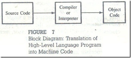
Now the question is: How do words in English get converted into the binary languages of different microprocessors? The answer lies with another program called either a compiler or an interpreter. These programs accept English-like statements as their input, called the source code. The compiler or interpreter ~hen translates the source code into the machine language compatible with the micro­processor being used in the system. This translation into the machine language is called the object code (Figure 1.7). Each microprocessor needs its own compiler or interpreter for each high-level language. The primary difference between a compiler and an interpreter is in the process of generating machine code. The compiler reads the entire program first and then generates the object code, while the interpreter reads one instruction at a time, produces its object code, and ex­ecutes the instruction before reading the next instruction. Compiled programs are executed much faster than interpreted programs. M-Basic is a common example of an interpreter for the BAS]C language. Compilers are generally used in such languages as C, FORTRAN, and PASCAL.

Compilers and interpreters require large memory space because each in­struction in English requires several machine codes to translate that instruction into binary. On the other hand, there is a one-to-one correspondence between the assembly language mnemonics and the machine code. Thus, assembly language programs are compact and require less memory space; they are more efficient than the high-level language programs. The primary advantage of high-level lan­guages is in troubleshooting programs, also known as debugging. It is much easier to find errors in a program written in a high-level language than to find them in a program written in assembly language.

In certain applications such as traffic control and appliance control, where programs are small and compact, assembly language is suitable. Similarly, in such real-time applications as converting a high-frequency waveform into digital data, program efficiency is critical. In real-time applications, events and time should closely match with each other without significant delay. Therefore, assembly lan­guage is highly desirable in these applications. On the other hand, for applications

MICROPROCESSOR INSTRUCTION SET AND COMPUTER LANGUAGES 21_03

FIGURE 7

Compiler

Object

Source Code

or

Interpreter

Code

Block Diagram: Translation of High-Level Language Program into Machine Code

MICROPROCESSOR ARCHITECTURE AND INTERFACING

in which programs are large and memory is not a limitation, high-level languages

may be desirable. The advantage of time saved in debugging a large program may outweigh the disadvantages of large memory requirements and inefficiency.
 

How Does the Microprocessor Work?

How Does the Microprocessor Work?

Assume that a program and data are already entered in the RJW memory. (How to write and execute a program will be explained later.) The program includes binary instructions to add given data. and to display the answer at the seven­ segment LEUs. When the microprocessor is given a command to execute the program, it reads and executes one instruction at a time and finally sends the result to the seven-segment LEDs for display.

This process of program execution can best be described by comparing it to the process of . assembling a radio kit .The instructions for assembling the radio are printed in a sequence on a sheet of paper. One reads the first instruction, then picks up the necessary components of the radio and performs the task. The sequence of the process is read. Interpret , and perform, The microprocessor works the same way. The instructions are stored sequentially in the memory. The micro­processor fetches the-first instruction from its memory sheet, decodes it, and executes that instruction. The sequence off etch. decode. and execute is contin­ued until the microprocessor comes across an instruction to stop, During the en­tire process, the microprocessor uses the system bus to fetch the binary instruc­tions and data from the memory. It uses registers from the register section to store data temporarily. and it performs the computing function in the ALU section. Finally, it sends out the result in binary. using the same bus lines ,to the seven segment LEDs.

Summary of Important Concepts

The functions of various components of a microprocessor-based system can be summarized as follows:

1. The microprocessor

· communicates with all peripherals(memory and I/Os) using the system bus.

· controls timing of information flow.

· performs the computing tasks specified in a program

2. The memory .

· stores binary instructions and data, called programs.

· provides the instructions and data to the microprocessor on request.

· stores results and data for the microprocessor.

3. The input device

· enters data and instructions under the control of a program such as a monitor program.

4. The output device

· accepts data from the microprocessor as specified in a program.

5. The bus

· carries bits between the microprocessor and memory and I/Os.

FROM LARGE COMPUTERS TO S~GLE-CHIP MICROCONTROLLERS

In the last thirty years, advances in semiconductor technology have had an un­precedented impact o-n computers. Thirty years ago, computers were-accessible only to big corporations, universities, and government agencies. Now, "com­puter" has become a common word. The range of computers now available ex­tends from such sophisticated, multimillion-dollar machines as the Cray com­puters to the less-than-$1000 personal computer. All the computers now available on the market include the same basic components shown in Figure 3. Neverthe­less, it is obvious that these computers are not all the same.

Different types of computers are designed to serve different purposes. Some are suitable for scientific calculations, while others are used simply for turning appliances on and off. Thus, it is necessary to have an overview of the entire spectrum of computer applications as a context for understanding the topics and applications discussed in this text. Until twenty years ago. computers were broadly classified in three categories: mainframe, mini-, and microcomputers. Since then, technology has changed considerably, and the distinctions between these categories have been blurred. Initially, the microcomputer was recognized as a computer with a microprocessor as its CPU. Now practically all computers have various types of microprocessors performing different functions within the large CPU. For the sake of convenience, computers are classified here as large .computers, medium-size computers, and microcomputers.

Large Computers

These are large, general-purpose computers designed to perform such data pro­cessing tasks as complex scientific and engineering calculations and handling records for large corporations or government agencies. The price is generally beyond $1 million and can range from $10 to $20 million. Typical examples of these com­puters are the IBM ES9000 series, Unisys A series, and Cray computers; they are generally known as mainframe computers. These are high-speed computers, and their word lengths range from 32 to 64 bits. They are capable of addressing mega­bytes of memory and handling all types of peripherals.

Medium-Size Computers

In the late 1960s, these computers were designed to meet the instructional needs of small colleges, the manufacturing problems of small factories, and the data processing tasks of medium-size businesses, such as payroll and accounting. They were called minicomputers. The price range was anywhere from $25,000 to $100,000. Typical examples include such computers as Digital Equipment Cor­poration (DEC) PDP 11/45 and Data General Nova.

These computers were slower than the large computers, and their word length generally ranged from 12 to 32 bits. They were capable of addressing 64K to 256K bytes of memory. Some of the larger minicomputers were known as midi computers. However, these classifications are no longer valid. For example, Digital Equipment’s VAX series is a 32-bit machine with megabytes of memory addressing capacity. The price ranges from $25,000 to $450.000. The high-end models of the VAX 9000 systems are classified as mainframe computers.

Microcomputers

The 4-bit and 8-bit microprocessors became available in the early 1970s, and initial applications were primarily in the areas of machine control and instrumentation. As the price of the microprocessors and memory began to decline, the applica­tions mushroomed in almost all areas, including video games, word processing, and small business applications. Early arrivals in the microcomputer market, such as Cromemco, North Star Horizon, Radio Shack TRS-80, and Apple, were de­signed around 8-bit microprocessors. Since then. 16-bit and 32-bit microproces­sors such as Intel 8086/88, 80286,80386. 80486; Motorola 68000; and Zilog Z8000 have been introduced, and recent microcomputers have been designed around these microprocessors. Present-day microcomputers can be classified into three groups: business (or personal), single-board, and single-chip microcomputers.

BUSINESS MICROCOMPUTERS

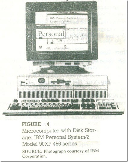
These microcomputers are being used for a variety of purposes, such as payroll, business accounts, word processing, legal and medical recordkeeping, personal finance, and instruction. They are also known as personal computers. Typically, the price ranges from $1,000 to $5,000 for a single-user system, and it can go higher for a multi-user system. Examples include the IBM personal computer (PC, XT, AT, and personal system 2 series). AT&T 6300 series, Apple and Macintosh, Zenith, and Compaq computers. Figure 4 shows an example.

FIGURE 4

Microcomputer with Disk Stor­age: IBM Personal System/2. Model 90XP 486 series

SOURCE: Photograph courtesy of IBM Corporation.

How Does the Microprocessor Work14_03

At the low end of the microcomputer spectrum, a typical configuration in­cludes a 16-bit microprocessor, 512K (or higher) bytes of system memory, a cath­ode ray tube (CRT) terminal. a dot matrix printer, dual disk drive for 5V4- and 3V2-inch floppy disks, and a 40 to 80 megabyte (MB) hard disk. The floppy disk is a magnetic medium similar to a cassette tape except that it is round like a record. Information recorded on these disks can be accessed randomly using disk drives. Conversely, information stored on a cassette tape is accessed serially. In order to read information at the end of the tape, the user must run the entire tape through the machine. The hard disk is similar to the floppy disk except that the magnetic material is coated on a rigid aluminum base that is enclosed in a sealed container and permanently installed in a microcomputer. The hard disk and the floppy disk are used to store programs semi permanently, i.e., the binary information does not disappear when the power is turned off. However, the microprocessor does not have direct access to this information; it must copy this information (programs) into system memory. The hard disk has a large storage capacity; therefore, large and frequently used programs such as compilers, interpreters, system programs. and application programs are stored on this disk. The floppy disk is generally used for user programs. At the high end of the microcomputer spectrum, the basic configuration remains essentially similar. It may include a high-speed, 16- or 32· bit microprocessor, a hard disk with 80 to 120 MB of storage, two disks, a high ­resolution CRT terminal, and a laser printer.

SINGLE-BOARD MICROCOMPUTERS

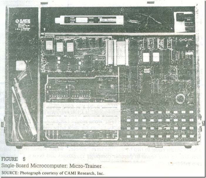
These microcomputers are used primarily in college laboratories and industries for instructional purposes or for evaluating the performance of a given microprocessor . They can also be part of some larger systems. Typically, these microcomputers include an 8-bit microprocessor, from 256 to 2K bytes of user memory ,a Hex keyboard, and seven-segment LEDs for display. The system monitor pro­grams of these computers are generally small; they are stored in less than 2K bytes of ROM. The prices of these single-board computers range from $100 to $800, with the average price being about $300.

Examples of these computers include such systems as Intel SDK-85, Mo­torola Evaluation Kit. E&L Instrument Fox Micro trainer , and CAMI Research Micro-Trainer (Figure 5). These are generally used to write and execute assem­bly language programs and to perform interfacing experiments.

SINGLE-CHIP MICROCOMPUTERS (MICROCONTROLLERS)

These microcomputers are designed on a single chip, which typically includes a microprocessor, 64 bytes of R/W memory, from I K to 2K bytes of ROM, and several signal lines to connect I/0s. These are complete microcomputers on a chip; they are also known as microcontrollers. They are used primarily for func­tions such as controlling appliances and traffic lights. Typical examples of these microcomputers include the Zilog Z8, Intel MCS 51 and 96 series, and Motorola 68HCII.

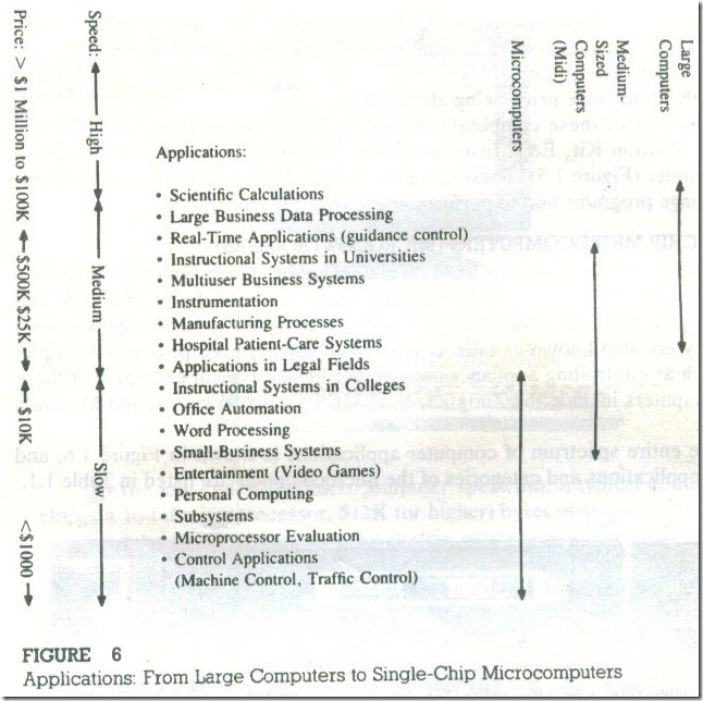
The entire spectrum of computer applications is shown in Figure 6, and various applications and categories of the microcomputer are listed in Table 1.

How Does the Microprocessor Work-15_03

f1GURE 5

Single- Board Microcomputer: Micro-Trainer SOURCE: Photograph courtesy of CAM I Research. Inc.

Applications:

• Scientific Calculations

• Large Business Data Processing

• Real-Time Applications (guidance control)

• Instructional Systems in Universities

• Multiuser Business Systems

• Instrumentation

• Manufacturing Processes

• Hospital Patient-Care Systems

• Applications in Legal Fields

• Instructional Systems in Colleges

• Office Automation

• Word Processing

• Small-Business Systems

• Entertainment (Video Games)

• Personal Computing

• Subsystems

• Microprocessor Evaluation

• Control Applications

(Machine Control, Traffic Control)

How Does the Microprocessor Work-16_03

FIGURE 6

Applications: From Large Computers to Single-Chip Microcomputers


Organization of a Microprocessor-Based System

Organization of a Microprocessor-Based System

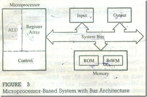
Figure 3 shows a simplified but formal structure of a microprocessor-based sys­tem or a product. Since a microcomputer is one among many microprocessor ­based systems, it will have the same structure as shown in Figure 3. It includes four components: microprocessor. input, output; and memory (Read/Write Mem­ory and Read-Only Memory). These components are organized around .a common communication path called a bus. The entire group of components is also referred to as a system or a microcomputer system, and the components themselves are referred to as sub-systems. At the outset, it is necessary to differentiate between the terms microprocessor and microcomputer because of the common misuse of these terms in popular literature. The microprocessor is one component of the microcomputer. On the other hand, the microcomputer is a complete computer similar to any other computer, except that the CPU functions of the microcom­puter are performed by the microprocessor. Similarly, the term peripheral ,is used for input/output devices. The various components of a microprocessor-based product or a microcomputer are shown in Figure 3 and their functions are de­scribed in this section.

The microprocessor is a semiconductor device consisting of electronic logic cir­cuits manufactured by using either a large-scale (LSI) or very-large-scale integra­tion (VLSI) technique. The microprocessor is capable of performing various computing functions and making decisions to change the sequence of program execution, In large computers, a CPU implemented on one or more circuit boards performs these computing functions. The microprocessor is in many ways similar to the CPU, but includes all the logic circuitry, including the control unit. on one chip. The microprocessor can be divided into three segments for the sake of clar­ity, as shown in Figure 3 : Arithmetic/Logic Unit (ALU), Register Array, and Control Unit .

MICROPROCESSOR

FIGURE 3

Microprocessor-Based System with Bus Architecture

Arithmetic/Logic Unit This is the area of the microprocessor where various com­puting functions are performed on data. The ALU unit performs such arithmetic operations as addition and subtraction, and such logic operations as AND, OR, and exclusive OR. Results are stored either in registers or in memory.

Register Array This area of the microprocessor consists of various registers. These registers are primarily used to store data temporarily during the execution of a program. Some of the registers are accessible to the user through instructions.

Control Unit The control unit provides the necessary timing and control signals to all the operations in the microcomputer, it controls the flow of data between the microprocessor and memory and peripherals .

Now the question is: what is the relationship among the programmer’s in­struction (binary pattern of 0s and 1s), the ALU, and the control unit ? This can be explained with the example of a Full Adder circuit .A Full Adder circuit can be designed with registers, logic gates, and a clock. The clock initiates the adding operation . Similarly, the bit pattern of an instruction initiates sequence of Clock signals, activates the appropriate logic circuits In the ALU , and performs the task.

This is called microprogramming , which is done in the design stage of the micro­processor. The bit patterns required to initiate these microprogram operations are given to the programmer in the form of the instruction set of the microprocessor. The programmer selects appropriate bit patterns from the set for a given task and enters them sequentially in memory through an input device. When the CPU reads these bit patterns one at a time, it initiates appropriate microprograms through the control unit, and performs the task specified in the instructions.

At present, various microprocessors are available from different manufac­turers. Examples of widely used 8-bit microprocessors include the Intel 8080/8085, Zilog Z80, and Motorola 6800 and 6809. Earlier microcomputers such as the Radio Shack TRS-80, the Televideo 803, and the Kaypro 4 were designed around the Z80 microprocessor. The recent versions of IBM personal computers, Personal System/2, are designed around 16-bit and 32-bit microprocessors; the model 60 is based on the Intel 80286 (16-bit), the model 80 is based on the Intel 80386 (32-bit), and the models 90 and 95 are based on the 80486 (32-bit) microprocessor. Single ­board microcomputers such as the Intel SDK-85, the Motorola MEK-6800-D2, the E&L Instrument Fox Microcomputer Trainer, and the CAMI Research Micro­trainer are commonly used in college laboratories; the SDK-85 is based on the 8085 microprocessor, the MEK-6800-D2 on the 6800 microprocessor, and the Fox -Trainer and the Micro-Trainer on the Z80 microprocessor.

INPUT

The input section transfers data and instructions in binary from the outside world to the microprocessor. It includes such devices as a keyboard, a teletype, and an analog-to-digital converter. Typically, a microcomputer used in college laborato­ries includes either a hexadecimal keyboard or an ASCII keyboard as an input device. The hexadecimal (Hex) keyboard has 16 data keys (0 to 9 and A to F) and some additional function keys to perform such operations as storing data and. executing programs. The ASCII keyboard (explained in Section I .3) is similar to a typewriter keyboard, and it is used to enter programs in an English-like lan­guage. Although the ASCII keyboard is found in most microcomputers, single­ board microcomputers generally have Hex keyboards, and microprocessor-based products such as a microwave oven have decimal keyboards.

OUTPUT

The output section transfers data from the microprocessor to such output devices as light emitting diodes (LEDs), a cathode-ray tube (CRT), a printer, a magnetic tape, or another computer. Typically, single-board computers and rnicroprocessor­ based products (such as a dishwasher) include LEOs, seven-segment LEOs, and alphanumeric LED displays as output devices.

MEMORY

Memory stores such binary information as instructions and data, and provides that information to the microprocessor whenever necessary. To execute pro­grams, the microprocessor reads instructions and data from memory and per­forms the computing operations in its ALU section. Results are either transferred to the output section for display or stored in memory for later use. The memory block shown in Figure 3 has two sections: Read-Only Memory (ROM) and Read! Write Memory (R/WM), popularly known as Random-Access Memory (RAM).

The ROM is used to store programs that do not need alterations. The mon­itor program of a single-board microcomputer is generally stored in the ROM. This program interprets the information entered through a keyboard and provides equivalent binary digits to the microprocessor. Programs stored in the ROM can only be read; they cannot be altered .

The Read/Write Memory (R/WM) is also known as user memory . It is used to store user programs and data. In single-board microcomputers, the monitor program monitors the Hex keys and stores those instructions and data in the R1W memory. The information stored in this memory can be easily read and altered.

SYSTEM BUS

The system bus is a communication path between the microprocessor and periph­erals; it is nothing but a group of wires to carry bits. In fact, there are several buses in the system that will be discussed 10 the next chapter. All peripherals (and memory) share the same bus; however, the microprocessor communicates with only one peripheral at a time. the timing is .provided by the control unit of the microprocessor.


MICROPROCESSORS

MICROPROCESSORS

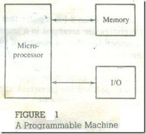
A microprocessor is a multipurpose, programmable logic device that reads binary instructions from a storage device called memory, accepts binary data as input and processes data according to those instructions, and provides results as output . A typical programmable machine can be represented with three components: mi­croprocessor. memory, and 110 as shown in Figure 1. These three components work to ether or interact with each other to perform a given task; thus, they­ comprise a system .The physical components of this system are called hardware.

A set of instructions written for the microprocessor to perform a task is called a program, and a group of programs is called software, The machine (system) rep­resented in Figure1. can be programmed to turn traffic lights on and off, com­pute mathematical functions, or keep track of a guidance system. This system may be simple or sophisticated, depending on its applications, and it is recognized ­by various names depending upon the purpose for which it is designed. The microprocessor applications are classified primarily in two categories: reprogrammable systems and embedded systems. In reprogrammable systems, such as microcomputers the microprocessor is used for computing and data processing. These systems include general-purpose microprocessors capable of handling large data, mass storage devices (disks), and peripherals such as printers; a Personal Computer (PC) is a typical illustration. In embedded stems, the microprocessor is apart of a final product and .is not available for reprogramming the end user.

A copying machine is a typical example of an embedded system . The micropro­cessors used in these systems are generally categorized as: (1) microcontrollers that include all the components shown in Figure 1. on one chip, (2) integrated ­microprocessors that include various devices (such as timers and various types of 1/0s)on a chip, and (3) general-purpose microprocessors with discrete compo­nents shown in Figure 1. Embedded systems can also be viewed as products that use microprocessors to perform their operations; they are known as microprocessor-based products. Examples include a wide range of products such as washing machines ,dishwashers, automobile dashboard controls, traffic light con­trollers, and automatic testing instruments.

MICROPROCESSORS

FIGURE 1. A Programmable Machine

BINARY DIGITS

The microprocessor operates in binary digits, g and I, also known as bits. Bit is an abbreviation for the term binary digit. These digits are represented in terms of electrical voltages in the machine: generally, 0 represents one voltage level, and J represents another. The digits 0 and 1 are also synonymous with low and high, respectively.

Each microprocessor recognizes and processes a group of bits called the word ,and microprocessors are classified according to their word length. For ex­ample, a processor with an 8-bit word is known as an 8.bit microprocessor, and a processor with a 16-bit word is known as a 16-bit microprocessor.

A MICROPROCESSOR AS A PROGRAMMABLE DEVICE

The fact that the microprocessor is programmable means it can be instructed to perform given tasks within its capability. A piano is 3 programmable machine; it is capable of generating various kinds of tones based on the number of keys it has. A musician selects keys depending upon the musical score printed on a Sheet. Similarly, today’s microprocessor is designed to understand and execute many binary instructions. It is a multipurpose machine: it can be used to perform vari­ous sophisticated computing functions, as well as simple tasks such as turning devices on or off: A programmer can select appropriate instructions and ask: the microprocessor to perform various tasks on a given set of data.

The person who designs a piano determines the frequency. ( tone ) for given key and the scope of the piano music. Similarly, the engineers designing a micro­processor determine a set of tasks the microprocessor; should perform and design the necessary logic circuits. and provide the user with a list of the instructions the ‘processor will understand. For example, an instruction for adding two numbers may look like a group of eight binary digits, such as 1000 QOOQ. These instructions are simply a pattern of Os and I s. The user (programmer) selects instructions from the list and determines the sequence of execution for a given task. These instructions are entered or stored in a storage device called memory, which can be read by the microprocessor.

MEMORY

Memory is like the pages of a notebook with space for a fixed number of binary numbers on each line. However, these pages are generally made of semiconductor material. Typically. each line is an 8-bit register that can store eight binary bits, and several of these registers are arranged in a sequence called memory. These registers are always grouped together in powers of two. For example, a group of 1024 (210) 8-bit registers on a semiconductor chip is known as 1 K byte of memory; 1 K is the closest approximation in thousands. The user writes the necessary. in­structions and data in memory through an input device (described below ) and asks the microprocessor to perform the given task and find an answer. The answer is generally displayed at an output device (described below) or stored in memory.

INPUT/OUTPUT

The user can enter instructions and data into memory through devices such as a keyboard or simple switches. These devices are called input devices .The micro­processor reads the instructions from the memory and processes the data accord­ing to those instructions. The result can be displayed by a device such as seven­ segment LEOs (Light Emitting Diodes) or printed by a printer. These devices are called output devices.

MICROPROCESSOR AS A CPU

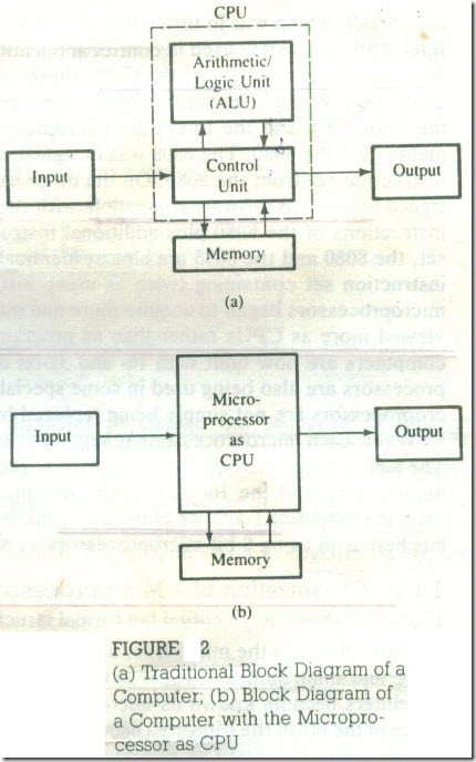
We can also view the microprocessor as a primary component of a computer. Traditionally, the computer is represented in block diagram as shown in Figure .2(a). The block diagram shows that the computer has four components: Mem­ory, Input, Output ,and the central processing unit (CPU),which consists of the Arithmetic/Logic Unit (ALU) and Control Unit. The CPU contains various reg­isters to store data ,the AL to perform arithmetic and logical operations ,in­struction decoders, counters ,and control lines .The CPU reads instructions from the memory and performs tile tasks specified . It communicates with input/output . devices either to accept or to send data .These devices are also known as peripherals . The CPU is the primary and central player in communicating with devices such as memory, input ,and output .However, the timing of the communication process IS controlled by the group of circuits called the control unit.

In the 1960s.,the CPU was designed with discrete component~ on various boards .With the advent of the integrated circuit technology, it became possible to build the CPU on a single chip; this came to be known as a microprocessor, and the traditional block diagram shown in Figure 1.2(a) can be replaced by the block diagram shown in Figure 2(b).

Advances in Semiconductor Technology

In the last forty years, semiconductor technology has undergone unprecedented changes. After the invention of the transistor, integrated circuits (ICs) appeared on the scene at the end of the 1950s; an entire circuit consisting of several tran­sistors, diodes, and resistors could be designed on a single chip. In the early 1960s, logic gates known as the 7400 series were commonly available as ICs, and the technology of integrating the circuits of a logic gate on a single chip became known as Small-Scale Integration (SSI). As semiconductor technology advanced, .more than 100 gates were fabricated on one chip; this was called Medium-Scale Integration (MSI)_ A typical example of MSI is a decade ,counter (7490). Within a few years, it was possible to fabricate more than 1000 gates on a single chip; this came to be known as Large-Scale Integration (LSI). Now we are in the era of Very-Large-Scale Integration (VLSI) and Super-Large-Scale Integration (SLSI). The lines of demarcation between these different scales of integration are rather ill-defined and arbitrary .

Programmable Machine

FIGURE 2

(a) Traditional Block Diagram of a Computer; (b) Block Diagram of a Computer with the Micropro­cessor as CPU

As the technology moved from SSl to LSI, more and more logic circuits. wore built on one chip, and they could be programmed to do different functions through hard-wired connections .For example, a counter chip can be programmed to count in Hex or decimal providing logic 0 or 1 through appropriate pin connections . the next step was the idea of providing 0s and 1s through a register. The necessary signal patterns of 0s and 1s were stored in registers and given to the programmable chip at appropriate times; the group of registers used for stor­age was called memory .Because of the LSI technology, it became possible to build, many computing functions and their related timing on a single chip.

The Intel 4004 was the first 4-bit programmable device that was primarily used in calculators. It was designed by Intel Corporation and became known as the 4-bit microprocessor. It was quickly replaced b the S-bit microprocessor (the Intel 8008), which was in turn superseded by the Intel 8080. In the mid-1970s, the, Intel 8080 was widely used in control applications.. and small computers also were designed using the 8080 as the CPU: these computers became known as micro­computers. Within a few years after the emergence of the 8080, the Motorola 6800 . the Zilog Z80, and the Intel 8085 microprocessors were developed as improve­ments over the 8080. The 6800 was designed with a different architecture and the instruction set from the 8080. On the other hand, the 8085and the Z80 were de­signed as upward software compatible with the 8080; that is, they included all the instructions of the 8080 plus additional instructions. In terms of the instruction .set, the 8080 and the 8085 are almost identical; however, the Z80 has a powerful instruction set containing twice as many instruction types as the 8080. As the microprocessors began to acquire more and more computing functions, they were viewed more as CPUs rather than as programmable logic devices. Most micro­computers are now built with 16-and 32-bit microprocessors, and 64-bit micro­processors are also being used in some special-purpose computers. The 8-bit mi­croprocessors are not simply being replaced by more powerful microprocessor~, however; each microprocessor has begun to carve a niche for its own applications. The 8-bit microprocessors are being used as programmable logic devices in control applications, and the 16- and 32-bit microprocessors are being used for mathe­matical computing (number crunching) and data processing applications. Our fo­cus here is in using 8′:bit microprocessors as programmable devices. .


Microprocessors, Microcomputers, and Assembly Language

Microprocessors, Microcomputers, and Assembly Language

Microprocessors, Microcomputers, and Assembly Language

this topic is concerned primarily with microprocessor architecture in the context of microprocessor-based products. The microprocessor-based systems are discussed in terms of three components the microprocessor, mem­ory, and input and output and their commu­nication process. The role of the programming languages, from the machine language to high-level languages, is presented in the context of the system.

The material is presented in a format sim­ilar to the view from an airplane preparing lo land. As the plane circles, one observes a view without any details. As the plane descends, one begins to see the same view but with more de­tails. Chapter I presents the microprocessor from two points of view: the microprocessor as a programmable embedded device in a product and as an element of a computer system, and how it communicates with memory and I/O. The chapter also discusses the role of assembly language in microprocessor-based products and presents an overview of various types of computers from large computers to microcomputers and their applications. we will  describes a generalized model of a micro­processor-based system and its three compo­nents: the microprocessor, memory, and input and output (I/O). we will examine these components in detail and discuss how memory and I/O devices interface with the Z80 microprocessor.

PREREQUISITES

The reader is expected to know the following

concepts:

· Number systems (binary, octal, and hexadec­imal) and their conversions.

· Boolean algebra, logic gates, flip-flops, and registers.

· Concepts in combinational and sequential logic.

Microprocessors, Microcomputers, and Assembly Language

The microprocessor plays a significant role in the everyday functioning of industrialized soci­eties. The microprocessor can be viewed as a programmable logic device that can be used to control processes or to turn on/off devices. On the other hand, the microprocessor can be viewed as a data processing unit or a computing unit of a computer. The, microprocessor is a pro­grammable integrated device that has comput­ing and decision making capability, similar to that of the central processing unit (CPU) of a computer. Nowadays, the microprocessor is being used in a wide range of products called microprocessor-based products or systems. The microprocessor can be embedded in a larger system, can be a stand alone unit controlling processes, or it can function as the CPU of a computer called a microcomputer. This chapter introduces the basic structure of a microproces­sor-based product and shows how the same structure is applicable to microcomputers and other large (mini- and mainframe) computers. Later in the chapter, microprocessor applica­tions are presented in the context of the entire spectrum of various computer applications.

The microprocessor communicates and operates in the binary numbers 0 and I, called bits. Each microprocessor has a fixed set of in­structions in the form of binary patterns called a machine language. However, it is difficult for humans to communicate in the language of Os and Is. Therefore, the binary instructions are given abbreviated names, called mnemonics, which form the assembly language for a given microprocessor. This chapter explains both the machine language and the assembly language of the microprocessor known as the Z80. The advantages of assembly language are compared with such English-like languages as Basic and FORTRAN.

OBJECTIVES

· Draw a block diagram of a microprocessor-based system and explain the functions of each component: microprocessor, memory, and I/O, and their lines of communication (the bus)

· Explain the terms SSI, MSI, and LSI.

· Define the terms bit, byte, word, instruction , software, and hardware

· Explain the difference between the machine language and the assembly language of a computer.

· Explain the terms low-level and high-level languages.

· Explain the advantages of an assembly lan­guage over high-level languages.


The Z80 and the 8051

The Z80 and the 8051

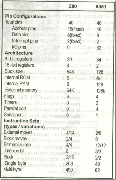
To see the differences in concept between a microprocessor and a micro­controller, in the following table we will examine the pin configurations, archi­tecture, and instruction sets for a 1980s-era 8-bit microprocessor, the Zilog Z80, and a microcontroller, the 8-bit Intel 8051:

The Z80 and the 80515_03

Note that the point here is not to show that one design is "better" than the other,- the two designs are intended to be used for different purposes and in dif­ferent ways. For example, the Z80 has a very rich instruction set. The penalty that is paid for this abundance is the number of multi-byte instructions needed, some 71% of the total number. Each byte of a multi-byte instruction must be fetched from program memory, and each fetch takes time; this results in longer program byte counts and slower execution time versus single-byte in­structions. The 8051 has a 62% multi-byte instruction content; the 8051 pro­gram is more compact and will run faster to accomplish similar tasks.

The disadvantage of using a lean instruction .set as in the 8051 is increased programmer effort (expense) to write code,- this disadvantage can be overcome when writing large programs by the use of high-level languages such as BASIC and C, both of which are popular with 8051 system developers. The price paid for reducing programmer time (there is always a price) is the size of the pro­gram generated.


Microprocessors and Microcontrollers

Microprocessors and Microcontrollers

Readers who have no prior concepts of computer operation should read Chapter 4 now.

Microprocessors and microcontrollers stem from the same basic idea, are made by the same people, and are sold to the same types of system designers and programmers. What is the difference between the two?

Microprocessors

A microprocessor, as the term has come to be known, is a general-purpose digital computer central processing unit (CPU). Although popularly known as a "computer on a chip," the microprocessor is in no sense a complete digital computer.

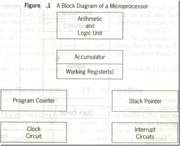
Figure .1 shows a block diagram of a microprocessor CPU, which contains an arithmetic and logic unit (ALU), a program counter (PC), a stack pointer (SP), some working registers, a clock timing circuit, and interrupt circuits.

To make a complete microcomputer, one must add memory, usually read­ only program memory (ROM] and random-access data memory (RAM], mem­ory decoders, an oscillator, and a number of input/output (I/O) devices, such as parallel and serial data ports. In addition, special-purpose devices, such as in­terrupt handlers and counters, may be added to relieve the CPU from time-consuming counting or timing chores. Equipping the microcomputer with mass storage devices, commonly a floppy and hard disk drives, and I/O periph­erals, such as a keyboard and a CRT display, yields a small computer that can be applied to a range of general-purpose software applications.

The key term in describing the design of the microprocessor is generalpurpose. The hardware design of a microprocessor CPU is arranged so that a small or very large system can be configured around the CPU as the application demands. The internal CPU architecture, as well as the resultant machine-level code that operates that architecture, is comprehensive but as flexible as possible.

The prime use of a microprocessor is to read data, perform extensive calculations on that data, and store those calculations in a mass storage device or display the results for human use. The programs used by the microprocessor. are stored in the mass storage device and loaded into RAM as the user directs. A few microprocessor programs are stored in ROM. The ROM-based programs are primarily small fixed programs that operate peripherals and other fixed de­vices that are connected to the system. The design of the microprocessor is driven by the desire to make it as expandable and flexible as possible, in the expectation of commercial success in the marketplace.

microprocessors

Microcontrollers

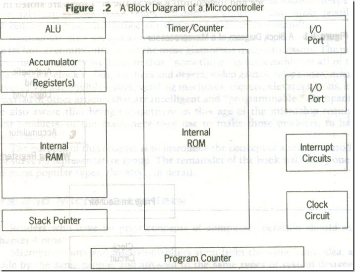
Figure.2 shows the block diagram of a typical microcontroller, which is a true computer on a chip. The design incorporates all of the features found in a micro-processor CPU: ALU, PC, SP, and registers. It also has added the other features needed to make a complete computer: ROM, RAM, parallel I/O, serial I/O, counters, and a clock circuit.

Like the microprocessor, a microcontroller is a general-purpose device, but one that is meant to read data, perform limited calculations on that data, and control its environment based on those calculations. The prime use of a micro­controller is to control the operation of a machine using a fixed program that is stored in ROM and that does not change over the lifetime of the system.

The design approach of the microcontroller mirrors that of the micro­processor: make a single design that can he used in as many applications as pos­sible in order to sell, hopefully, as many as possible. The microprocessor de­sign accomplishes this goal by having a very flexible and extensive repertoire of multi-byte instructions. These instructions work in a hardware configura­tion that enables large amounts of memory and I/O to be connected to address and data bus pins on the integrated circuit package. Much of the activity in the microprocessor has to do with moving code and data to and from external memory to the CPU. The architecture features working registers that can be programmed to take part in the memory access process, and the instruction set is aimed at expediting this activity in order to improve throughput. The pins that connect the microprocessor to external memory are unique, each having a single function. Data is handled in byte, or larger, sizes.

microprocessors3_03

microprocessors4_03

The microcontroller design uses a much more limited set of single- and double-byte instructions that are used to move code and data from internal memory to the ALU. Many instructions are coupled with pins on the integrated circuit package,- the pins are "programmable"—that is, capable of having sev­eral different functions depending on the wishes of the programmer.

The microcontroller is concerned with getting data from and to its own pins; the architecture and instruction set are optimized to handle data in bit and byte size.

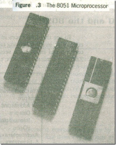
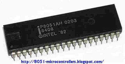
Figure .3 is a photograph of several members of the 8051 family.Comparing Microprocessors and Microcontrollers

The contrast between a microcontroller and a microprocessor is best exemplified by the fact that most microprocessors have many operational codes (opcodes) for moving data from external memory to the CPU; microcontrollers may have one or two. Microprocessors may have one or two types of bit-handling instructions; microcontrollers will have many.

To summarize, the microprocessor is concerned with rapid movement of code and data from external addresses to the chip; the microcontroller is concerned with rapid movement of hits within the chip. The microcontroller can function as a computer with the addition of no external digital parts; the micro­processor must have many additional parts to be operational .


Microprocessors and Micro controllers

Microprocessors and Micro controllers

objectives

On successful completion of this chapter, you will be able to:

• List the differences between microcontrollers and microprocessors.

• Describe the prominant standard features of a typical microcontroller.

• Name several contemporary microcontroller manufacturers and notable features of their products.

• Identify the major components of a microcontroller development system.

Introduction

The past three decades have seen the introduction of a technology that has radically changed the way in which we analyze and control the world around us. Born of parallel developments in computer architecture and integrated circuit fabrication, the microprocessor, or "computer on a chip," first became a commercial reality in 1971 with the introduction of the 4-bit 4004 by a small, unknown company by the name of Intel Corporation. Other, more well-established, semiconductor firms soon followed Intel’s pioneering technol­ogy so that by the late 1970s we could choose from a half dozen or so micro­processor types.

The 1970s also saw the growth of the number at personal computer users from a handful of hobbyists and "hackers" to millions of business, industrial, governmental, defense, educational, and private users now enjoying the advan­tages of inexpensive computing.

A by-product of microprocessor development was the microcontroller. The same fabrication techniques and programming concepts that make possible the general-purpose microprocessor also yielded the microcontroller.

Microcontrollers are not as well known to the general public, or to many in the technical community, as are the more glamorous microprocessors. The pub­lic is, however, very well aware that "something" is responsible for all of the smart VCRs, clock radios, washers and dryers, video games, telephones, micro­waves, TVs, automobiles, toys, vending machines, copiers, elevators, irons, and a myriad of other articles that are intelligent and "programmable." Companies are also aware that being competitive in this age of the microchip requires their products, or the machinery they use to make those products, to have some "smarts."

The purpose of this chapter is to introduce the concept of a microcontroller and survey a representative group. The remainder of the book will study one of the most popular types, the 8051, in detail.


8051 technical data features and Core Specification


the 8051 is popular 8 bit microcontrollers and has an instruction set that enable coding of tiny,I/O intensive, application . with large Program Memory that it is possibly to be used with C. it is manufacturers by  Intel . greatly used in embedded systems. now  manufactured by may independent manufacturers . the designation for this family is MCS 51.
the
microcontrollers was build using NMOS . however the version recognize by a C (80C51) use CMOS , This enable it to be more appropriate for battery operated devices.


instruction time:

It has an instruction time of 1µs ( at 12 MHz)  newer one may perform 40 instructions per 1µ at 40 MHz.

 
with useful feature such as:

  • it has 4  separate register sets, which can be used to  reduce interrupt delay contrasted to,  storing interrupt context on a stack.
  • it has a boolean engine which allows bit-level boolean operations . This feature useful  for control applications.


8051 features and  Core Specification
 

  • It has many module (CPU,ROM , RAM, I/O,timer , interrupt logic, etc.) in 1 integrated circuit
  •  data bus with  8 bit width( permit access to  eight bits of data in 1 operation)
  • 8 bit ALU, Accumulator and 8-bit Registers
  •  address bus with  16 bit widthpermit access to  64 K of memory (65536 locations) for  ROM and RAM
  • On-chip ROM – 4 K (program memory)
  • On-chip RAM – 128 bytes (data memory)
  • 64KB Program Memory
  • 64KB Data Memory
  • 5-vector/6-source interrupt structure
  • 2-level interrupt priority
  • Two 16-bit timers/Counter
  •  bi-directional 4 byte output/input port
  • serial port with (UART)
  • Power economizing mode