Code Memory Read-Only Data Moves

Code Memory Read-Only Data Moves

Data moves between RAM locations and 8051 registers are made by using MOV and MOVX opcodes. The data is usually of a temporary or "scratch pad" nature and disap­pears when the system is powered down.

There are times when access to a preprogrammed mass of data is needed, such as when using tables of predefined bytes. This data must be permanent to be of repeated use and is stored in the program ROM using assembler directives that store programmed data anywhere in ROM that the programmer wishes.

Access to this data is made possible by using indirect addressing and the A register in conjunction with either the PC or the DPTR, as shown in Figure 3.2. In both cases, the number in register A is added to the pointing register to form the address in ROM where the desired data is to be found. The data is then fetched from the ROM address so formed and placed in the A register. The original data in A is lost, and the addressed data takes its place.

As shown in the following table, the letter C is added to the MOV mnemonic to high­light the use of the opcodes for moving data from the source address in the Code ROM to the A register in the 8051:

Mnemonic

Operation

MOVC A,@A+DPTR

Copy the code byte, found at the ROM address formed by adding A and the DPTR, to A

MOVC A,@A+PC

Copy the code byte, found at the ROM address formed by adding A and the PC, to A

Note that the DPTR and the PC are not changed; the A register contains the ROM byte found at the address formed.

The following table shows examples of code ROM moves using register and indirect addressing modes:

Mnemonic

Operation

MOV DPTR,#1234h

Copy the immediate number 1234h to the DPTR

MOV A,#56h

Copy the immediate number 56h to A

MOVC A,@A+DPTR

Copy the contents of address ͞1͞͞2͞8͞͞A͞h͞ to A

MOVC A,@A+PC

Copies the contents of address 4059h to A if the PC contained 4000h and A contained 58h when the opcode is executed.

CAUTION

The PC is incremented by one (to point to the next instruction) before it is added to A to form the final address of the code byte.

All data is moved from the code memory to the A register.

MOVC is normally used with internal or external ROM and can address 4K of internal or 64K bytes of external code.


Indirect Addressing Mode

Indirect Addressing Mode

For all the addressing modes covered to this point, the source or destination of the data is an absolute number or a name. Inspection of the opcode reveals exactly what are the addresses of the destination and source. For example, the opcode MOV A,R7 says that the A regis­ter will get a copy of whatever data is in register R7; MOV 33h,#32h moves the hex number 32 to hex RAM address 33.
The indirect addressing mode uses a register to hold the actual address that will finally be used in the data move; the register itself is not the address, but rather the number in the register. Indirect addressing for MOV opcodes uses register R0 or R1, often called “data pointers,” to hold the address of one of the data locations, which could be a RAM or an SFR address. The number that is in the pointing register (Rp) cannot be known un­less the history of the register is known. The mnemonic symbol used for indirect address­ing is the “at” sign, which is printed as @.
The moves made possible using immediate, direct, register and indirect addressing modes are as follows:
Mnemonic Operation
MOV @ Rp, #n Copy the immediate byte n to the address in Rp
MOV @Rp,add Copy the contents of add to the address in Rp
MOV @Rp ,A Copy the data in A to the address in Rp
MOV add,@ Rp Copy the contents of the address in Rp to add
MOV A,@ Rp Copy the contents of the address in Rp to A
The following table shows examples of MOV opcodes, using immediate, register, direct, and indirect modes
Mnemonic Operation
MOV A,@R0 Copy the contents of the address in R0to the A register
MOV @R1,#35h Copy the number 35h to the address in R 1
MOV add,@R0 Copy the contents of the address in R0 to add
MOV @R1,A Copy the contents of A to the address in R 1
MOV @R0,80h Copy the contents of the port 0 pins to the address in R0

CAUTION

The number in register Rp must be a RAM or an SFR address. Only registers R0 or R1 may be used for indirect addressing. 

External Data Moves

As discussed in Chapter 2. it is possible to expand RAM and ROM memory space by adding external memory chips to the 8051 microcontroller. The external memory can be as large as 64K bytes for each of the RAM and ROM memory areas. Opcodes that access this external memory always use indirect addressing to specify the external memory.
Figure 3.2 shows that registers R0. R1. and the aptly named DPTR can be used to hold the address of the data byte in external RAM. R0 and R1 are limited to external RAM address ranges of 00h to 0FFh. while the DPTR register can address the maxi­mum RAM space of 0000h to 0FFFFh.
An X is added to the MOV mnemonics to serve as a reminder that the data move is external to the 8051. As shown in the following table.
Mnemonic Operation
MOVX A.@Rp Copy the contents of the external address in Rp to A
MOVX A.@DPTR Copy the contents of the external address in DPTR to A
MOVX @Rp.A Copy data from A to the external address in Rp
MOVX @DPTR.A Copy data from A to the external address in DPTR
The following table shows examples of external moves using register and indirect addressing modes:
Mnemonic Operation
MOVX @DPTR.A Copy data from A to the 16-bit address in DPTR
MOVX @R0,A Copy data from A to the 8-bit address in R0
MOVX A,@R1 Copy data from the 8-bit address in R 1 to A
MOVX A,@DPTR Copy data from the 16-bit address in DPTR to A

CAUTION

All external data moves must involve the A register.
Rp can address 256 bytes; DPTR can address 64K bytes.
MOVX is normally used with external RAM or I/O addresses.
Note that there are two sets of RAM addresses between 00 and 0FFh: one internal and one external to the 8051.
 

Direct Addressing Mode

Direct Addressing Mode

All 128 bytes of internal RAM and the SFRs may be addressed directly using the single ­byte address assigned to each RAM location and each special-function register.

Internal RAM uses addresses from 00 to 7Fh to address each byte. The SFR addresses exist from 80h to FFh at the following locations:

SFR

ADDRESS (HEX) OED

A

0E0

B

0F0

DPL

82

DPH

83

IE

0A8

IP

0B8

PO

80

Pl

90

P2

DAD

P3

080

PCON

87

PSW

0DD

SBUF

99

SCON

98

SP

81

TCON

88

TMOD

89

TH0

8C

TL0

8A

TH1

8D

TLl

8B

Note the use of a leading 0 for all numbers that begin with an alphabetic (alpha) character.

RAM addresses 00 to 1Fh are also the locations assigned to the four banks of eight working registers, R0 to R7. This assignment means that R2 of register bank 0 can be

addressed in the registermodeasR2orinthedirectmodeas02h.The direct addresses of

the working registers are as follows:

BANK REGISTER

ADDRESS (HEX)

BANK REGISTER

ADDRESS (HEX)

0

R0

00

2

R0

10

0

R1

01

2

R1

11

0

R2

02

2

R2

12

0

R3

03

2

R3

13

0

R4

04

2

R4

14

0

R5

05

2

R5

15

0

R6

06

2

R6

16

0

R7

07

2

R7

17

1

R0

08

3

R0

18

1

R1

09

3

R1

19

1

R2

0A

3

R2

1A

1

R3

0B

3

R3

1B

1

R4

0C

3

R4

1C

1

R5

0D

3

R5

1D

1

R6

0E

3

R6

1E

1

R7

0F

3

R7

1F

Only one bank of working registers is active at any given time. The PSW special­ function register holds the bank-select bits, RSO and RS 1, which determine which register bank is in use.

When the 8051 is reset, RS0 and RS 1 are set to 00b to select the working registers in bank 0, located from 00h to 07h in internal RAM. Reset also sets SP to 07h, and the stack will grow up as it is used. This growing stack will overwrite the register banks above bank 0. Be sure to set the SP to a number above those of any working registers the program may use.

The programmer may choose any other bank by setting RS0 and RS 1 as desired; this bank change is often done to "save" one bank and choose another when servicing an interrupt or using a subroutine.

The moves made possible using direct, immediate, and register addressing modes are as follows:

Mnemonic

Operation

MOV A, add

Copy data from direct address add to register A

MOV add ,A

Copy data from register A to direct address add

MOV Rr, add

Copy data from direct address add to register Rr

MOV add, Rr

Copy data from register Rr to direct address add

MOV add, #n

Copy immediate data byte n to direct address add

MOV add I ,add2

Copy data from direct address add2 to direct address add1

The following table shows examples of MOV opcodes using direct, immediate, and register addressing modes:

Mnemonic

Operation

MOV A,80h

Copy data from the port 0 pins to register A

MOV 80h,A

Copy data from register A to the port 0 latch

MOV 3Ah,#3Ah

Copy immediate data byte 3Ah to RAM location 3Ah

MOV RO,12h

Copy data from RAM location 12h to register RO

MOY 8Ch,R7

Copy data from register R 7 to timer 0 high byte

MOY 5Ch,A

Copy data from register A to RAM location 5Ch

MOY OA8h,77h

Copy data from RAM location 77h to IE register

CAUTION

MOV instructions that refer to direct addresses above 7Fh that are not SFRs will result in errors. The SFRs are physically on the chip; all other addresses above 7Fh do not physically exist.

Moving data to a port changes the port latch; moving data from a port gets data from the port pins.

Moving data from a direct address to itself is not predictable and could lead to errors.


Moving Data

Moving Data

Outline:

o Introduction

o Addressing Modes

o External Data Moves

o PUSH and POP Opcodes

o Data Exchanges

o Example Programs

o Summary

Introduction

A computer typically spends more time moving data from one location to another than it spends on any other operation. It is not surprising, therefore, to find that more instructions are provided for moving data than for any other type of operation.

Data is stored at a source address and moved (actually, the data is copied) to a desti­nation address. The ways by which these addresses are specified are called the addressing modes. The 8051 mnemonics are written with the destination address named first. fol­lowed by the source address.

A detailed study of the operational codes (opcodes) of the 8051 begins in this chapter.

Although there are 28 distinct mnemonics that copy data from a source to a destination, they may be divided into the following three main types:

1. MOV destination. source

2. PUSH source or POP destination

3. XCH destination, source

The following four addressing modes are used to access data:

1. Immediate addressing mode

2. Register addressing mode

3. Direct addressing mode

4. Indirect addressing mode

The MOV opcodes involve data transfers within the 8051 memory. This memory is divided into the following four distinct physical parts:

1. Internal RAM

2. Internal special-function registers

3. External RAM

4. Internal and external ROM

Finally, the following five types of opcodes are used to move data:

1. MOV

2. MOVX

3. MOVC

4. PUSH and POP

5. XCH

Addressing Modes

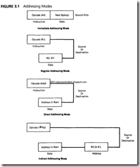
The way in which the data sources or destination addresses are specified in the mnemonic that moves that data determines the addressing mode. Figure 3.1 diagrams the four ad­dressing modes: immediate. register, direct. and indirect.

Immediate Addressing Mode

The simplest way to get data to a destination is to make the source of the data part of the opcode. The data source is then immediately available as part of the instruction itself.

When the 8051 executes an immediate data move, the program counter is automat­ically incremented to point to the byte(s) following the opcode byte in the program mem­ory. Whatever data is found there is copied to the destination address.

The mnemonic for immediate data is the pound sign (#). Occasionally, in the rush to meet a deadline, one forgets to use the # for immediate data. The resulting opcode is often a legal command that is assembled with no objections by the assembler. This omis­sion guarantees that the rush will continue.

Register Addressing Mode

Certain register names may be used as part of the opcode mnemonic as sources or destina­tions of data. Registers A, DPTR, and R0 to R7 may be named as part of the opcode mnemonic. Other registers in the 8051 may be addressed using the direct addressing mode. Some assemblers can equate many of the direct addresses to the register name (as is the case with the assembler discussed in this text) so that register names may be used in lieu of register addresses. Remember that the registers used in the opcode as RO to R7 are the ones that are currently chosen by the bank-select bits, RS0 and RSI in the PSW.

The following table shows all possible MOV opcodes using immediate and register addressing modes:

Mnemonic Operation

· MOV A, #n Copy the immediate data byte n to the A register

· MOV A, Rr Copy data from register Rr to register A

· MOV Rr, A Copy data from register A to register Rr

· MOV Rr, #n Copy the immediate data byte n to register Rr

· MOV DPTR, #nn Copy the immediate 16-bit number nn to the DPTR register

Addressing Modes


Pages-from-Hardware---The-8051-Microcontroller-Architecture,-Programming-and-Applications-1991_Page_03_Image_0001_03


A data MOV does not alter the contents of the data source address. A copy of the data is made from the source and moved to the destination address. The contents of the destina­tion address are replaced by the source address contents. The following table shows ex­amples of MOV opcodes with immediate and register addressing modes:

Mnemonic Operation

· MOV A,#0Flh Move the immediate data byte F1 h to the A register

· MOV A,R0 Copy the data in register RO to register A

· MOV DPTR,#0ABCDh Move the immediate data bytes ABCDh to the DPTR

· MOV R5,A Copy the data in register A to register R5

· MOV R3,#1Ch Move the immediate data byte I Ch to register R3

CAUTION

It is impossible to have immediate data as a destination.

All numbers must start with a decimal number (0-9), or the assembler assumes the number is a label.

Register-to-register moves using the register addressing mode occur between registers A and RO to R7.


ASSIGNMENTS on Software Development Systems and Assemblers

ASSIGNMENTS

Check the appropriate answer in 1-10.

1. The process of accessing information on a floppy disk is

a. random.

b. serial.

c. semirandom.

2. The operating system of a computer is defined as

    1. hardware that operates the floppy disk.
    2. a program that manages files on the disk.
    3. a group of programs that manages and directs hardware and software in the system.

3. The Editor is

  1. an assembly language program that reads and writes information on the disk.
  2. a high-level language program that allows the user to edit programs.
  3. a program that allows the user to write, modify, and store text in the computer system.

4. The Assembler is

  1. a compiler that translates statements from high-level language into assembly language.
  2. a program that translates mnemonics into binary code.
  3. an operating system that manages all the programs in the system.

5. A file is

a. a group of related records stored as a single entity.

b. a program that transfers information between the system and the floppy disk.

c. a program that stores data.

6. The COM (TSK) file

  1. consists of Hex digits and is used for communication.
  2. is the only file that can be interpreted and executed by the microprocessor.
  3. consists of Z80 mnemonics.

7. The Hex file generated by the Assembler is used primarily

  1. to reduce the memory requirement for storing files.
  2. to transfer a file from one system to another.
  3. to transfer a file between a floppy disk and the system’s R/W memory.

8. The assembler directive DB (or DEFB)

  1. reserves a specified number of memory locations.
  2. stores data bytes written after the directive in successive memory locations.
  3. defines bytes as decimal, Hex, or Octal.

9. A disk controller is

  1. a program that manages the files on the disk.
  2. a circuit that interfaces the disk with the microcomputer system.
  3. a mechanism that controls the spinning of the disk.

10. The MS-DOS is

  1. an operating system that is designed primarily to handle the communication between the l6-bit microprocessor and its peripherals.
  2. a master disk that stores all system programs.
  3. an application program that handles communication between various systems.

11. Assemble the following program with the starting address l820H, and print the LST file. The address of the output port OUTPRT is 07H

Untitled-33_03


Untitled-34_03


SUMMARY of Software Development Systems and Assemblers

SUMMARY

A software development system and an assembler are essential tools for writing, assembling, testing, and debugging large assembly language programs.

A disk-based microcomputer, its operating system, and assembler pro­grams can serve as a development system. All the operations of the computer are managed and directed by the operating system of the computer. The Assem­bler and other utility programs assist the user in developing software. The Edi­tor allows the user to enter text, and the Assembler translates mnemonics into machine code and provides error messages. The Debugger assists in debugging the program. The cross-assembler is an assembler program that operates under one type of MPU and can translate mnemonics of another MPU.

The program thus assembled is in many ways similar to that of the hand assembly program except that the program written for the assembler includes assembler directives, which are instructions concerning how to assemble the program. The assembler has many advantages over manual assembly; without the assembler, it would be extremely difficult to develop industry-standard software.


WRITING PROGRAMS USING A CROSS-ASSEMBLER

7.4 WRITING PROGRAMS USING A CROSS-ASSEMBLER

This section describes a commercially available Z80 cross-assembler and the pro­cess of assembling a program. The description in the following sections is equally applicable to both assemblers and cross-assemblers; therefore, the term assem­bler should be interpreted as the representation of both. The assembly process is illustrated with a simple example from the last chapter.

7.4.1 Z80Cross-Assembler

The Z80 cross-assembler from 2500AD Software, Inc. * is one among several of such commercially available products. It includes two programs: X80 and LINK. In this assembler, translating mnemonics into binary code is a two-step process. The X80 translates the source file into modules of the Z80 code and generates two files: one is called the list (LST) file, and the other is called the object (OBJ) file. (This assembly process and the file names may vary slightly from assembler to assembler.) In addition to translating mnemonics, the assembler performs various functions, such as error checking and memory allocations.

The list (LST) file includes the source file plus the memory addresses and the Hex code of each instruction. This file is primarily used for documentation and may look like the hand-assembled file shown in the last chapter under pro­gram documentation or writing format.

The object file is an intermediate file that is used by the Link program to generate an executable binary COM (or TSK) file. The object file is necessary to combine different modules (or programs) and relocate the modules from one block of memory to another block of memory. In addition, the object file is used to generate the Hex file that can be used to transfer the program from the IBM PC to a Z80 single-board computer. This transfer of files among different systems is called downloading and uploading of files. This program assembly process is de­scribed in more detail in section 7.4.2 with an illustrative program. In addition, some editors also generate a back (BAK) file. When the user calls the source file for reediting, the editor copies the source file as the BAK file before the user begins to reedit, in case the user elects to retrieve the original file.

The complete assembly process on a software system such as the IBM PC can be summarized in the following steps:

1. Call up an editor program such as PC-Write or Wordstar, and write an assem­bly language program (statements) using an editor. Save the program. This is called the source program.

2. Call an assembler such as X80, use the source program as the input to the X80, and generate the object (OBJ) file and the list (LST) file.

3. If the assembler finds errors in the program, go back to Step 1 and correct the errors in the source program. Then repeat Step 2.

4. If the file needs to be transferred directly to a single-board computer, call the Link program (LlNK2) to generate the HEX file. This file is used to download the program from the IBM PC to the single-board computer if the download facility is available in the system. Otherwise, the Hex code can be loaded man­ually using the Hex keyboard into R/W memory of the single-board computer.

5. A binary executable file called COM or TSK file can be generated from the object file by using another Link program (LINK)). Generally, this step is unnecessary because the Z80 binary code cannot be executed by a system such as IBM PC.

Upon completion of the assembly process, the user can have the following files:

· Source file. This is the file written by the user using an editor. Generally, a file name can be eight characters long with an extension of three characters. The file name and the extension are separated by a period. For example, the file name can be DELAY 1.ASM; the extension ASM suggests that it is an assembly language file.

· OBJ file. This is a binary file generated by the assembler (X80) without any specific reference to the user memory. This file is used to generate an execut­able binary file called TSK (or COM) file and relocate the entire program for storage to specified memory locations.

· LST file. This is the list file generated by the assembler program (X80) for doc­umentation purposes. It contains memory locations, Hex code, mnemonics, and comments. This file looks like a manually assembled program, as shown in Section 6.3.2.

· HEX file. This is generated by the Linker (LINK2) program and contains pro­gram code in hexadecimal notations. This file can be used for debugging the program and transferring files from one system to another system.

· TSK file. This is the executable file generated by the Linker (LINK1) program, and it contains binary code; this is the only file that can be understood and executed by the microprocessor.

· BAK file. When the source file is called for reediting, the previous file is saved as the BAK file.

4.4.2 Illustrative Program: Addition of Two Hexadecimal Numbers

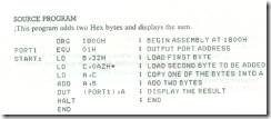
To illustrate how to write a source program, the example is taken from the last chapter, where it was assembled manually. The source program is written using an editor under the file name PROGRAM 1.ASM and assembled using the assem­bler X80 described earlier. The problem statement is repeated here for conve­nience; refer to section 6.3.1 for analysis.

PROBLEM STATEMENT

Write instructions to load the two hexadecimal numbers 32H and A2H into registers Band C, respectively. Add the numbers, and display the sum at the LED output port PORT1

Untitled-29_03

This program illustrates the following assembler directives:

· ORG

The object code will be stored starting at the location 1800H

· EQU

The program defines one equate: PORT1. In this program it would have been easier to write the port address directly with the instructions. However, equates are essential in development projects where hardware and software design are done concurrently, and they are also useful in long programs because they make it easy to change or redefine port addresses.

· Label

The program illustrates one label: START. This label represents the memory location I800H• In this illustration, the label is not particularly useful; generally, labels are used to specify Jump and Call addresses. In writing assembly lan­guage programs, it is convenient to identify a Jump or Call address by a label • because absolute addresses are not known in the beginning. Also, if any changes (deletions and additions) are made in the source program, the assem­bler will reassign all label addresses when it is reassembled. In manual assem­bly, the entire program must be rewritten with new addresses if any changes are to be made.

· End

The end of assembly.

TWO-PASS ASSEMBLER

To assemble the program, the assembler scans through the program twice; this is known as a two-pass assembler. In the first pass, the first memory location is determined from the ORG statement, and the counter known as the location counter is initialized. Then the assembler scans each instruction and records lo­cations in the address column of the first byte of each instruction; the location counter keeps track of the bytes in the program. The assembler also generates a symbol table during the first pass. When it comes across a label, it records the label and its location. In the second pass, each instruction is examined, and mne­monics and labels are replaced by their machine codes.

ASSEMBLED LIST FILE

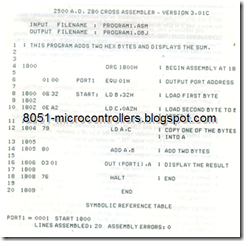
A list (LST) file generated from the source program (PROGRAM 1.ASM) by the X80 assembler is shown here.

Untitled-30_03

The LST file has five columns: memory addresses, Hex codes, labels, mne­monics, and comments. It lists the memory addresses of the first byte of each instruction with its Hex codes on the same line. For example, the listing shows that the first memory address is 1800 and the first two Hex codes are 06 32; the next address is 1802. Therefore, it is understood that the memory address 1801 and holds the Hex byte 32. In addition to the program listing, the LST file includes the list of symbols, equates, and error messages.

Error Messages In addition to translating the mnemonics into object code, the assembler also gives error messages. These messages are of two types: terminal error messages and source program error messages. In the first case, the assem­bler is not able to complete the assembly. In the second case, the assembler lists the errors, but it is able to complete the assembly.

GENERATING COM (TSK) AND HEX FILES

This assembler has two Linker programs: LINK1 and LINK2; these programs use the OBJ file generated by the X80 program. The LINK1 generates the exe­cutable binary (TSK) file, and the LINK2 creates the HEX file that can be used to transfer the file from the IBM PC system to a single-board computer.

Precautions in Writing Programs Assembler programs are available from various software companies, and for the most part, they follow a similar format. However, we suggest the following precautions in writing assembly language programs.

  1. Some assemblers impose a rigid format in which the source code must be writ­ten. For example, X80 must have a label starting in column 1. Similarly, it generates an error code if there is a space between operands. For example, in the first instruction (LD B, 32H), if there is a space between B and the comma, or between the comma and 32H, the X80 will generate an error message.
  2. The letter following a number specifies the type of a number. A hexadecimal number is followed by the letter "H," an octal by letter "O," a binary by letter • "B." A number without a letter is interpreted as a decimal number.
  3. Any Hex number that begins with A through F must be preceded by zero; otherwise, the assembler interprets the number as a label and gives an error message because it cannot find the label.
  4. Some assemblers require a colon after a label.
  5. When a 16-bit address is used in a mnemonic (such as Jump to 1850H), the X80 prints the address as 1850; however, it is stored in the reverse order in memory. Some assemblers print the address as 50 18.

USING AN INTEGRATED EDITOR-ASSEMBLER PROGRAM

An integrated editor-assembler software development package is available from CAMI Research" to assemble Z80 programs. One of the drawbacks of the assem­bly process described earlier is the need to go back and forth between the editor and the assembler until all the errors are corrected. This integrated software pack- age is menu driven, and the programs (editor, assembler, and linker) are integrated in one package. The program can identify errors and enable the user to edit them.


ASSEMBLERS

7.3 ASSEMBLERS

The assembler (or the cross-assembler), as defined before, is a program that trans­lates assembly language mnemonics or source code into binary executable code. Here, we are using the term assembler to include all the utility programs (such as Assembler and Linker) necessary for the assembly process. This translation pro­cess requires that the source program be written strictly according to the specified syntax of the assembler. The assembly language source program includes three types of statements:

1. The program statements in Z80 mnemonics, which are to be translated into binary code.

2. Comments, which are reproduced as a part of the program documentation.

3. Directives to the assembler that specify such items as starting memory loca­tions, label definitions, and required memory spaces for data.

The first two types of statements have been used in the program of adding two Hex numbers in the last chapter. The format of these statements as they appear in an assembly language source program is identical to the format used here. The third type-directives-and their functions will be described in Section 7.3.2.

7.3.1 Assembly Language Format

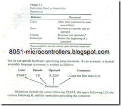
A typical assembly language programming statement is divided into four parts, called fields: label, operation code (opcode), operand, and comments. These fields are separated by delimiters as shown in Table 7.1.

The assembler statements have a free-field format, which means that any number of blanks can be left between fields. Comments are optional but are gen­erally included for good documentation. A label for an instruction is also optional,

Untitled-24_03

7.3.2 Assembler Directives

The assembler directives are the instructions to the assembler concerning the pro­gram being assembled; they are also called pseudo operations or pseudo-ops, these instructions are neither translated into machine code nor assigned any memory locations in the object file. Some of the important assembler directives for the Z80 assembler are listed and described here.

Assembler Directives

Example

Description

1.ORG (Origin)

ORG 0100H

The next block of instruc­tions should be stored in memory locations starting from 0100H.

2.END

END

End of assembly. The HALT instruction sug­gests the end of a pro­gram, but that does not necessarily mean the end of assembly.

3. EQU

(Equate)

PORT1 EQU 01H

The value of the term PORT1 is equal to 01H. Generally, this means the PORT1 has the port ad­dress 01H.

INBUF EQU 1899H

The value of the term INBUF is 1899H. This may be the memory loca­tion used as input buffer.

OUTBUF EQU INBUF + 4

The equate can be ex­pressed by using the label of another equate. This example defines the OUTBUF memory location in terms of INBUF.

4.DB or DEFB (Define Byte)

DATA: DEFB A2H, 9FH

Initializes an area byte by byte, in some assemblers either symbol (DB or DEFB) can be used. As­sembled bytes of data are stored in successive mem­ory locations until all val­ues are stored. This is a convenient way of writing a data string. The label is optional.

5. DW or DEFW (Define Word)

DEFW 2050H

Initializes an area of two bytes at a time. In some assemblers either symbol (DW or DEFW) can be used. This statement re­serves two locations for 2050H

6. DS or DEFS (Define Storage)

OUTBUF: DEFS 4

Reserves a specified num­ber of memory locations. In this example, four mem­ory locations are reserved for OUTBUF,

7. Constant Suffix D, B, Q, H

32H 0A5H 97

Numerical values can be expressed in decimal (D), binary (B), octal (Q), or Hex (H). Hexadecimal dig­its from A to F must be preceded by 0 as shown by 0A5H, and any number without a suffix is consid­ered-decimal.

7.3.3 Advantages of the Assembler

The assembler is a tool for developing programs with the assistance of the com­puter. Assemblers are absolutely essential for writing industry-standard software; manual assembly is quite time-consuming for programs larger than 50 instruc­tions. The assembler performs many functions in addition to translating mnemon­ics, and it has several advantages over manual assembly. The salient features of the assembler are as follows:

1. The assembler translates mnemonics into binary code with speed and accu­racy, thus eliminating human errors in looking up the codes.

2. The assembler assigns appropriate values to the symbols used in a program. This facilitates specifying jump locations.

3. It is easy to insert or delete instructions in a program; the assembler can quickly reassemble the entire program with new memory locations and modi­fied addresses for jump locations. This avoids rewriting the program manually.

4. The assembler checks syntax errors, such as wrong labels and expressions, -and provides error messages. However, it cannot check logic errors in a program.

5. The assembler can reserve memory locations for data or results.

6. The assembler can provide files for documentation.

7. A Debugger program can be used in conjunction with the assembler to test and debug an assembly language program.

CAUTION

A correctly assembled program with zero errors does not mean it is a working program. The assembler cannot check the logic of the program; it checks only the syntax of the program.


OPERATING SYSTEMS

7.2 OPERATING SYSTEMS

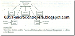
The operating system of a computer is a group of programs that manages or over­sees all the operations of the computer. The computer transfers information con­stantly among peripherals such as a floppy disk, printer, keyboard, and video monitor. It also stores user programs under file names on a disk. (A file is defined as related records stored as a single entity.) The operating system is responsible primarily for managing the files on the disk and the communication between the computer and its peripherals. The functional relationship between the operating system and the computer’s various subsystems is shown in Figure 7.3.
Untitled-18_03

Each computer has its own operating system. Nowadays, the most widely used operating system for IBM PC-compatible microcomputers is MS-DOS. In the 1970s and early 1980s when most microcomputers were designed to use 8-bit microprocessors, the CP/M (Control Program/Monitor) operating system was commonly used. The MS-DOS and CP/M are in many ways similar to each other, except that the MS-DOS is designed to handle 16-bit (or 32-bit) microprocessors and 1 M byte memory, and the CP/M was designed for 8-bit microprocessors and 64K byte memory.

7.2.1 MS-DOS Operating System

In 16-bit microcomputers, such as IBM PC, XT, AT, and PS/2, the MS-DOS (Mi­crosoft Disk Operating System) is so widely used that it has become the industry standard. Initially, when it was installed on IBM PC, it was known as PC-DOS; the terms MS-DOS and PC-DOS are interchangeable. The MS-DOS is designed to handle 16-bit data word and large-size one-megabyte system memory and disks with high memory capacity such as 720K and 1.44M. Similarly, it can support a hard disk and includes a hierarchical file directory. The latest version of MS-DOS is geared toward handling communication between multiuser systems.

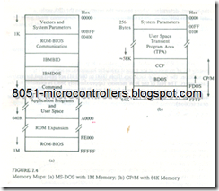
The MS-DOS operating system is divided into four components: Boot Re­cord, IO.SYS, MSDOS.SYS, and COMMAND.COM. In the PC-DOS, these components are identified as ROM-BIOS, IBMBIO, lBM DOS, and COM­MAND.COM, respectively. In a typical 1M (1.024K) system, the memory space is divided into 16 blocks from 0 to F, each being 64 K byte memory; the Hex address ranges from 00000 to FFFFFH. Generally, the lowest addresses in 0 block are reserved for system software, the highest block F is used for IO.SYS, and approximately ten blocks (640K) are reserved as the user memory. The remaining blocks are used for such various purposes as video display and BIOS extensions. See Figure 7.4(a).

BOOT RECORD AND ROM-BIOS

The boot record works in conjunction with the set of instructions stored perma­nently in ROM. The boot record is a program that loads the MS-DOS into the system memory, and ROM includes the program to initialize the hardware. The boot record is stored on track 0 and sector I of a formatted disk. When the system is turned on or reset, the program in ROM initializes the hardware parameters and reads first sector of track 0. Then the boot record loads IO.SYS and MSDOS.SYS into beginning locations of the system memory and passes the con­trol to IO.SYS.

IO.SYS (IBMBIO.COM)

The primary function of this program is to communicate with I/O devices when it receives commands from a user’s program; it works in conjunction with a set of instructions in ROM. The program defines peripheral port addresses and enables additions of new peripherals; thus, it is device-dependent and -modified by hard-
Untitled-20_03

ware manufacturers. The IO.SYS passes the control to MS-DOS after initializing the peripheral.

MS-DOS (IBMDOS)

This program directs the activities of the disk controller and also contains DOS service routines; these service routines include such programs as DIR (Directory), FORMAT (Formatting Disk), and COPY (Copying files). The program generates the tables in memory that are used by the COMMAND.COM program.

COMMAND. COM

This program reads and interprets the commands from the keyboard and differ­entiates between the DOS services (such as COPY) and the utility programs (such as DEBUG). This is an interface between the user and the MS-DOS.

Once the COMMAND. COM is executed, the booting process is completed, and the MS-DOS is ready to accept commands from the user. Figure 7.4(a) shows where the MS-DOS resides in the system memory and the memory space avail­able for the user’s programs. The user writes programs in a transient portion of the memory, and when the Save command is given, the MS-DOS takes control of the system, determines where to save the program on the disk under a-file name, and regains control of the system.

7.2.2 CP/M Operating System

The CP/M operating system is designed to handle 8-bit data words and 64K bytes ‘system memory. It is divided into three components: BIOS (Basic Input/ Output System), BDOS (Basic Disk Operating System), and CCP (Console Command Processor).

When CP/M is loaded into a system’s R/W memory, it occupies approxi­mately 6K of memory at the highest available locations, as shown in Figure 7.4(b). In addition, the first 256 locations (from 0000 to 00FFH) are reserved for system parameters. The rest of the R/W memory (approximately 58K) is available for the user. Once the operating system is loaded into R/W memory, the user can write, assemble, test, and debug programs y using utility programs (described in the next section).

7.2.3 Tools for Developing Assembly Language Programs

In addition to the operating system of a computer, various programs called utility programs are necessary to develop assembly language programs. These programs can be classified in two categories: (1) file-management utilities and (2) program ­development utilities. The file-management utilities are programs that enable the user to perform such functions as copying, printing, erasing, and renaming files. In MS-DOS, some programs such as COPY (Copy), DEL (Delete), and DIR (Di­rectory) are part of the internal commands, meaning these programs are loaded into system memory along with the operating system. Other programs, such as PRINT (Print), FORMAT (Formatting Disk), and MODE (to set up printer op­tions) are part of the external commands, meaning these programs are stored on the disk under file names and copied into system memory whenever they are needed. The program development utilities enable the user to write, assemble, and test assembly language programs; they include programs such as Editor, As­sembler Linker (or Loader )Debugger, and cross-assemblers. The descriptions of various programs and the assembly process described below may vary in de­tails depending upon an operating system, its utility programs, and an assembler being used.

EOITOR

The Editor is a program that allows the user to enter, modify, and store a group of instructions or text under a file name. The Editor programs can be classified in two groups: line editors and full-screen editors. Line editors, such as EDLIN (Edit Line) in MS-DOS, work with and manage one line at a time. On the other hand, full-screen editors (also known as word processors), such as PC-Write, ‘Word Star, and Word Perfect, manage the full screen or a paragraph at a time. To write text, the user must call the Editor under the control of the operating system. As soon as the Editor program is transferred from the disk to the system memory, the program control is transferred from the operating system to the Editor program. The Editor has its own commands, and the user can enter and modify text by using those commands. At the completion of writing a program, the exit com­mand of the Editor program will save the program on the disk under the file name and will transfer the program control back to the operating system. This file is known as ‘a source file or a source program. If the source file is intended to be a program in the Z80 assembly language, the user should follow the syntax of the assembly language and the rules of the assembler that are described next.

The Editor program is not concerned with whether one is writing a letter or an assembly language program. The full-screen editors are convenient to write either line- or paragraph-oriented text; they automatically adjust lines as words are typed, and the text can be modified or erased with ease.

ASSEMBLER

The Assembler is a program that translates so’ .rce code or mnemonics into the binary code, called object code, of the microprocessor and generates a file called the Object file. This function is similar to manual assembly, whereby the user looks up the code for each mnemonic in the listing. In addition to translating mnemonics, the Assembler performs various functions, such as error checking and memory allocations. The Assembler is described in more detail in Section 7.3.

LINKER

The Linker (or Loader) is a program that takes the object file generated by the Assembler program and generates a file in binary code called the COM file or the EXE file. The COM (or EXE) file is the only executable file-i.e., the only file that can be executed by the microcomputer. To execute the program, the COM file is called under the control of the operating system and executed. In different assemblers or cross-assemblers, the COM file may be labeled by other names such as TSK file.

DEBUGGER

The Debugger is a program that allows the user to test and debug the object file. The user can employ this program to perform the following functions:

· Make changes in the object code.

· Examine and modify the contents of memory.

· Set breakpoints, execute a segment of the program, and display register con- ‘tents after the execution.

· Trace the execution of the specified segment of the program, and display the register and memory contents after the execution of each instruction .

· Disassemble a section of the program, i.e., convert the object code into the source code or mnemonics.

MS-DOS AND CROSS-ASSEMBLERS

The MS-DOS is an operating system designed primarily for 16-bit microproces­sors. This raises a question: Why are we discussing the operating system meant for l6-bit processors in the context of 8-bit microprocessors such as the Z80? The answer lies with the widespread use of IBM PCs or their compatibles on college campuses. However, the microprocessor used in the IBM PC (Intel 8088 type family) has different mnemonics than that of the Z80; thus, we need a program that can translate the Z80 mnemonics but operate under the 16-bit microproces­sor. Such a program is called a cross-assembler. The assembly process using a cross-assembler (described in Section 7.4) is similar to that of an assembler under a Z80 system. After assembling a program, the Hex file (discussed later) can be directly transferred to the R/W memory of a Z80 sin le-board microcomputer by using a download program. Thus, programs and/or hardware-related laboratory experiments can be easily performed.

 

MICROPROCESSOR-BASED SOFTWARE DEVELOPMENT SYSTEMS

7.1 MICROPROCESSOR-BASED SOFTWARE DEVELOPMENT SYSTEMS

A software development system is simply a computer that enables the user to write, modify, debug, and test programs. In a microprocessor-based development system, a microcomputer is used to develop software for a particular micropro­cessor. Generally, the microcomputer has a large R/W memory (640K bytes or higher), disk storage, and a video terminal with a typewriter-like keyboard. The keyboard enables the user to write programs in- alphanumeric (alphabet and num­ber) characters, which are translated into American Standard Code for Informa­tion Interchange (ASCII) binary code; the keyboard (or the terminal) is known as ASCII keyboard (or terminal). The system includes programs that enable the user to develop software in either assembly language or high-level languages. This text will focus on developing programs in the Z80 assembly language.

Conceptually, this type of microcomputer is similar to a single-board micro­computer except that it has additional features that can assist in developing large’ programs. Programs are accessed and stored under a file name (title), and they are written by using such other programs as text editors and translated into binary code by using assemblers. The system (I/Os, files, programs, etc.) is managed by a program called the operating system. The various hardware and software fea­tures of a typical software development system are described in the next sections.

7.1.1 System Hardware and Storage Memory

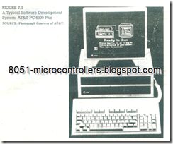
Figure 7.1 shows a typical software development system; it includes an ASCII keyboard, a CRT terminal, an MPU board with R/W memory (around 640) and disk controllers, and two disk drives. The disk controller is an interfacing circuit through which the MPU can access a disk and provide Read/Write control signals. The disk drives have Read/Write elements that are responsible for reading and writing data on the disk. Two types of floppy disks are in use: 51/4-inch and 31/4 312­inch. A 5V4-inch single-density disk can store about 90K bytes of data; the storage capacity can be doubled by using double-density disks, and quadrupled (to 360K) by using both sides of the disks. A high-density 5V4-inch disk can store 1.2M bytes. A 3V2-inch double-sided double-density disk stores 740K bytes, and high-

z80 Interfacing and programming-16_03

density stores 1.44M bytes. In addition, most systems nowadays have a perma­nently installed hard disk with memory capacity of 10M to 120M bytes.

FLOPPY DISK

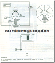
A floppy disk-Figure 7.2(a)-is made of a thin magnetic material (iron oxide) that can store logic 0s and 1s in the form of magnetic directions. The surface of the disk is divided into a number of concentric tracks, each track divided into sectors, as shown in Figure 7.2(b). The large hole in the center of the disk is locked by the disk drive when it spins the disk. The small hole shown in Figure 7.2(a) is known as the indexing hole. The disk drive uses this hole as a reference to count the sectors. The oblong cutout, called the head slot, is the reading/recording segment; this is the only segment of the surface that comes in contact with the R/W head. At the edge of the disk, near the head slot, is a notch called the Write Protect notch. If this notch is covered, data cannot be written on the disk; the disk is then "Write Protected." Figure 7.2(c) shows a typical 3 1/2 -inch disk.

Each sector and track is assigned a binary address by using a program (FORMAT); this is called formatting a disk. The MPU can access any information on the disk with the sector and the track addresses; however, the access is semi-

z80 Interfacing and programming-17_03

random. To go from one track to another, the access is random. Once the track is found, the system waits for the index hold and then locates the sector serially by counting the sectors. Once data bytes are located, they are transferred to the system’s R/W memory. These data transfer functions between a floppy disk and the system are performed by the disk controller and controlled by the operating system, also known as the Disk Operating System (DOS), described in Section 7.12.

HARD DISK

Another type of storage memory used with computers is called a hard disk or Winchester disk. The hard disk is similar to the floppy disk except that the mag­netic material is coated on a rigid aluminum base and enclosed in a sealed con­tainer. While it is highly precise and reliable, the hard disk requires sophisticated controller circuitry. However, its storage capacity is quite large. Hard disks are available in various sizes; 31/2 -inch, 51/4-inch, and 14-inch. Storage capacity can range from several megabytes to several gigabytes.