ILLUSTRATIVE PROGRAM 3: BLOCK TRANSFER OF DATA BYTES USING Z80 SPECIAL INSTRUCTIONS

ILLUSTRATIVE PROGRAM 3: BLOCK TRANSFER OF DATA BYTES USING Z80 SPECIAL INSTRUCTIONS


nn

This program transfers data from one memory block to another using the Z80 instruction LDIR.

Problem Statement

Modify the illustrative program (Section 8.6.3) using the instruction LDIR with the problem statement as follows: Transfer 1024 (1K) bytes from the memory block SOURCE (0000H) to the memory block OUTBUF (1900H), and indicate the end of data transfer by displaying 01 at PORT0.

Problem Analysis

To use the instruction LDIR, the HL register should be used to point to memory SOURCE and the DE register to the destination OUTBUF, and the register BC should be used as the counter with the 16-bit count (03FFH = 1024 bytes).

Program

Label

Mnemonics

Comments

START:

LD HL, SOURCE

;Set up HL as pointer for SOURCE memory

LD DE, OUTBUF

;Set up DE as pointer for OUTBUF memory

LDBC, 03FFH

;Specify the number of bytes in BC

LDIR

;Transfer data byte from SOURCE to OUT-

; BUF and repeat until BC = 0

LDA, OIH

;Load display indicator

OUT (PORTO), A

;Display end of data transfer

HALT

;End of program

Program Description

In this program, the instruction LDIR is the workhorse: it replaces several in­structions from the illustrative program in Section The instruction performs three operations: (1) copies a data byte from the memory location shown by the HL register into the memory location indicated by the DE register, (2) updates memory pointers (HL and DE) and the counter (BC), and (3) makes the decision· to repeat or terminate the loop based on the count in the BC register. When all 1024 (1K) bytes are copied into new locations, the counter BC becomes· zero, and the program goes on to display 01 at PORT0


Z80 SPECIAL INSTRUCTIONS

Z80 SPECIAL INSTRUCTIONS

tt

The Z80 instruction set includes some instructions that perform more than one task. These instructions improve programming efficiency considerably. Some of these instructions are:

Mnemonics

Description

DJNZ d

Decrement B and Jump Relative on no zero (Z = 0)

The instruction decrements register B, and if B # 0, it jumps to the memory address specified by the offset value d.

LDI

Load and Increment

The instruction copies a data byte from the memory location shown by HL into the memory location indicated by DE_. Reg­isters HL and DE are incremented. and BC is decrement

LDIR

Load, Increment, and Repeat

This is similar to the instruction LDI, except that it is repeated until BC= 0.

LDD

Load and Decrement

The instruction copies a data byte from the memory location shown by HL into the memory location pointed to by DE. Registers HL, DE, and BC are decremented.

LDDR

Load, Decrement; and Repeat

This instruction is similar to LDD, except that it is repeated until BC= 0

Example

Modify the illustrative program Addition with Carry (Section 8. 7) using the in­struction DJNZ and the offset value.

Solution

The following mnemonics are repeated from a segment of the program in Figure; we assume that the segment is stored in memory locations starting from l808H.

Location

Label

Mnemonics

Comments

1808

NXTBYT:

LD D, (HL)

;Get data byte from input buffer

1809

ADDA,D

;Add data byte

180A

JP NC, SKIPCY

;If no carry, do not save CY

180D

INCC

;Save carry bit

180E

SKIPCY:

INC HL

;Point to next memory location

180F

DJNZ F7H

;Decrement counter B, and if B # 0, jump to location 1008 to get the next byte

Program Description and Calculation of the Offset Value In this program, the instruction DJNZ replaces two instructions-DEC B and JP NZ, NXTBYT-from the program in Figure 8.10. The instruction DJNZ assumes that register B is used as a counter. When the Z80 executes the 2-byte instruction DJNZ, the program counter holds the address 1811H. This is a backward jump; therefore, the offset value must be in 2’s complement. The offset value for the jump location NXTBYT (1808H) is obtained as follows:

Program Counter:

1 8

11

Jump Location:

I 8

08

09H

F7H

(0 0 0 0 1 0 0 1)

2’s Complement of 09H

(1111 0 111)

for backward jump:


DEBUGGING A PROGRAM

DEBUGGING A PROGRAM

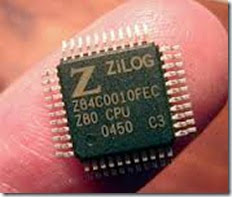
b-zilog-z80-cpu

Debugging a program is similar to troubleshooting hardware, but it is much more difficult and cumbersome. When a program fails to work, very few clues alert you to what exactly went wrong. Therefore, it is essential to search carefully for the errors in the program logic, machine code, and execution.

The debugging procedure can be divided into two parts: static debugging and dynamic debugging. Static debugging is similar to visual inspection of a circuit board; it is the paper-and-pencil check of a flowchart and machine code. Dynamic debugging involves observing out puts; register contents, and flags following the execution of either instruction (the single-step technique) or a group of instruc­tions (the breakpoint technique).

Static Debugging of Machine Code

Translating the assembly language into the machine code is similar to building a circuit from a schematic in that the machine code will have errors just as would the circuit board. If an assembler is used to translate the code, most of the errors involved in hand assembly can be eliminated. The following errors are common in manual assembly:

I. Selecting a wrong code.

1. Forgetting the second byte or third byte of an instruction.

2. Specifying the wrong jump location.

3. Not reversing the order of high and low bytes in a Jump instruction.

4. S. Writing memory addresses in decimal, thus specifying wrong jump locations.

The debugging problems given in the Assignments section at the end of the chapter will illustrate some of these errors.

Dynamic Debugging

Dynamic debugging is concerned with observations of data after executing an instruction or a set of instructions. These observations may include verifying out­put displays, checking flags, examining register contents, and tracing execution flow. The process is similar to that of the signal-injection technique in trouble­shooting analog circuits, which involves injecting a signal into a hardware system (such as an amplifier) and checking signals at various points against the expected outputs. Similarly, in debugging programs, we execute a few instructions and check register contents or outputs against the expected results. The commonly used techniques and tools are (1) Single Step, (2) Register Examine, and (3) Breakpoint.

SINGLE STEP

The single step technique allows us to execute one instruction at a time and to observe the results following each instruction. As we advance through each in-striation, we will be able to observe memory addresses and codes as they are executed. With the single step technique, we can spot

· Incorrect addresses.

· Incorrect jump locations for loops.

· Incorrect data or missing codes.

This technique is generally used in conjunction with the Register Examine facility (described below), and it is very useful for short programs (50-100 machine codes). For larger programs, the technique is cumbersome and time consuming.

REGISTER EXAMINE

The Register Examine facility allows us to examine the contents of the micropro­cessor registers and the flags. We can examine registers after the execution of each instruction or after the execution of a group of instructions and compare the contents with the expected outcomes.

BREAKPOINT

The breakpoint technique allows us to check the program in segments. We can set a breakpoint at the end of a program segment or multiple breakpoints at vari­ous memory locations. When the microprocessor is asked to execute the program, it executes the codes until it comes across the first breakpoint, where it returns the control to the breakpoint subroutine in the system. At this point, we can ex­amine the registers· for expected results. If the segment of the program is found satisfactory, the program can be executed up to the next breakpoint. With the breakpoint technique, we can isolate the segments of the programs with errors and debug those segments with the single step technique. The breakpoint tech­nique is generally used to check out timing loops, I/O sections, and interrupts.

COMMON SOURCES OF ERRORS

In addition to the errors mentioned in Section other common errors in the types of programs discussed in this chapter are:

· Failure to clear the accumulator when it is used to add data.

· Failure to clear registers when they are used to store partial results or carries.

· Failure to update an index or a counter.

· ·Failure to set a flag before using a conditional Jump instruction or use of an inappropriate flag.

· Inadvertently changing a flag before using a Jump instruction.


Data Copy Between Z80 Registers and Memory

Data Copy Between Z80 Registers and Memory

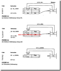
To copy data from and into memory, the 16-bit address of a selected memory register must be specified, and this memory address can be specified by using indirect, direct, or other addressing modes in the indirect addressing mode, the address of a memory location is loaded into the HL register, and the register (HL) with the parentheses is used as a memory pointer to copy data. Registers BC and, DE can also be used in this manner, with some restrictions. In the direct addressing mode, the 16-bit address of a memory location is used as the operand of the copy instruction. Methods using index registers are-discussed after the discussion of 2’s complement arithmetic because the index registers include a displacement byte, which is expressed as a signed 2’s complement number. In Z80 mnemonics, the memory address is enclosed in parentheses, as shown in the following list.

Opcode

Operand

Bytes

Addressing

Modes

Description

LD

r, (HL)

Example: LD B, (HL)

1

Register Indirect

Copy contents of memory into register r.

The memory address is specified indi­rectly by the number in the HL register; therefore, this is called register indirect addressing.

LD

(HL), r

Example: LD (HL), C

1

Register Indirect

Copy contents of register r into memory, the address of which is in HL.

LD

(HL), 8-bit Example: LD (HL), 97H

2

Register Indirect & Immediate

Copy 8-bit data into memory. This mode is a combination of indirect and immediate addressing.

Note: In these three instructions, the memory address is specified by the contents of register HL, and register r can be any one of the general-purpose registers.

LD

A, (rp)

1

Register Indirect

Copy contents of memory into accumulator.

LD

(rp), A

Example: LD (BC), A

1

Register Indirect

Copy contents of accumulator into memory.

Note: In the preceding two instructions, the-memory address is shown by the contents of a register pair (BC or DE). However, these instructions can copy data from and into the accumulator only.

LD

A, (16-bit)

3

Extended

Copy contents of memory into accumulator.

LD

(16-bit), A

Example: LD (2050H), A

3

Extended

Copy contents of accumulator into memory.

Note: In these instructions, the memory address is the 16-bit operand, and these instructions can copy data from and into the accumulator only.

General Characteristics

I. No flags are affected by these data copy operations.

2. Memory-related data copy operations can be recognized by the parentheses around the operand.

3. Register HL is a versatile memory pointer; a data byte can be copied from any memory location to any general-purpose register and vice versa. In addition, HL can be used to load a byte directly into memory.

4. A 16-bit direct address and other register pairs (BC and DE) can be used as memory pointers to copy data from a memory location into the accumulator and vice versa. However, these memory pointers cannot be used to copy data between general-purpose registers and memory.

Example

The memory location 2050H contains the data byte 37H. Write instructions to copy the byte from the memory location into register B. Illustrate three different ways of transferring the byte from memory to the microprocessor, and list the associ­ated machine codes.

Solution

1. The first method of copying a byte from memory into the microprocessor is by using the HL register as a memory pointer; this is an illustration of indirect addressing. First, we need to load the memory address into the HL register and then use the contents of HL as a memory pointer .

2. The second method of copying a byte from memory into the microprocessor is by using BC or DE as a memory pointer; this is also the indirect addressing . However, these registers (BC and DE) can be used as pointers to copy into A only. Therefore, one more instruction is necessary to copy from A into B.

3. The third technique is to use the direct extended addressing copies a data byte from memory into A and then into B.

Example

The memory location 2040H contains the data byte F2H. copy the data byte F2H from the memory location 2040H into 2070H using memory pointers Then, clear the memory location 2040H. Enter the machine codes of these instructions in memory locations starting from 2000H Describe how data copy operations are performed.

Solution

Memory Address

Hex Code

Opcode

Operand

Comments

2000

21

LD

HL, 2040H

; Set up HL as memory pointer for 2040H

2001

40

2002

20

2003

01

LD

BC, 2070H

; Set up B£; as memory pointer for 2070H

2004

70

2005

20

2006

7E

LD

A, (HL)

; Copy data (F2H) into accumulator

2007

02

LD

(B,C),A

; Copy data into memory (2070H)

2008

36

LD

(HL), 00

; Clear location 2040H

2009

00

200A

76

HALT


Assembly Language Programming (2)

Description

1. The first two instructions load registers HL and BC with the numbers 2040H and 2070H, respectively, These are not memory-related data copy instructions because the operands Jack parentheses.

2. The next two instructions copy the data byte (F2H) stored in memory location 2040H into the accumulator and from the accumulator into location 2070H

Assembly Language Programming (3)

3. The next instruction LD (HL), 00 is a 2-byte instruction; it clears the memory location 2040H by loading 00 into the memory location pointed to by the H register.


ILLUSTRATIVE PROGRAM 2: ADDITION WITH CARRY

ILLUSTRATIVE PROGRAM 2: ADDITION WITH CARRY

The following program adds the number of bytes stored in memory and counts the number of carries generated. The maximum sum can be up to 16-bit.

Problem Statement

Add the following ten data bytes stored in memory with the starting address INBUF (Input Buffer). Store the sum in two memory locations; the low-order byte of the sum should be stored in OUTBUF and the high-order byte in OUTBUF + 1.

Data (H): A2; 37, 4F, 97, 22, 6B, 75, 8E, 9A, C7.

Problem Analysis

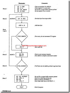
This problem is similar to Example 8.11 and can be very easily analyzed in terms of the blocks shown in the generalized flowchart in Figure.

1. In the initialization block, we need to set up a counter to count ten bytes, a memory pointer for INBUF, and registers to save the partial sum and carries. We use the accumulator for addition. The memory pointer for OUTBUF is not necessary until the data processing is completed: thus, the memory pointer used for INBUF can also be used for OUTBUF.

2. In this problem, the data processing block needs to be expanded because of the carries. Whenever a carry is generated after an addition, the carry register Will be incremented; thus, the high-order byte of the sum Will be saved in the carry register, and the low-order byte will be in the accumulator.

Program Description and Execution

The comments written in the program (see Figure) explain the function of each instruction, and the blocks drawn around the instructions show the sequence of execution. However, Figure should not be used or viewed as an illustration of a flowchart.

In the initialization block, the accumulator and register C are cleared for use in arithmetic operations; otherwise, residual data would cause erroneous results. However, register D need not be specifically cleared because the first load in­ ruction replaces its residual data.

This program has two types of loops; one loop repeats the addition-related instructions if the counter is not zero, and the second loop skips the carry counter if there is no carry. The instruction ADC (Add with Carry) is inappropriate for this problem; this instruction is used for 16-bit addition (see Appendix A).

In the output block, the HL register is used again as a memory pointer for the output buffer memory. After all bytes have been added, the low-order byte of the result, which is in the accumulator, is stored in the memory location OUTBUF, and the high-order byte (carries) in register C is stored in the next memory location OUTBUF + 1.

Program Assembly (Assembly of ADDITION.ASM)

This section shows an illustration of the listing file of the program assembled using an assembler, This listing illustrates.how to store data using the Define Byte (DEFB) pseudo-op.

Assembly Language Programming (Assembly Language Programming7)Assembly Language Programming (Assembly Language Programming8)Assembly Language Programming (Assembly Language Programming9)


ILLUSTRATIVE PROGRAM 1: BLOCK TRANSFEER OF DATA BYTES

ILLUSTRATIVE PROGRAM 1: BLOCK TRANSFEER OF DATA BYTES

In practical applications, data transfer from one memory block to another is a com­mon occurrence. This illustrative program demonstrates how to copy data bytes from one block of memory to another using the instructions discussed previously.

Problem Statement

Ten bytes of data are stored in a block of memory; the first location is labeled SOURCE (1850H). Transfer all data bytes to a new block starting with the location labeled OUTBUF (Output Buffer = 1870H). When the data transfer is complete, display 01 at the output port PORT0.

Problem Analysis

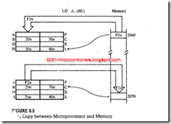
Ten bytes are already stored in the memory block from 1850H to 1859H (Figure). These bytes must be copied into the memory block from I870H to 1879H; these are called no overlapping memory blocks. This problem is similar to Ex­ample repeated ten times. Therefore, we must copy one byte from 1850H into

the Z80 microprocessor and then copy the byte into 1870H as shown in Figure. This process should be repeated ten times for the remaining bytes.

We can analyze this problem in terms of the generalized flowchart (Figure).

1. Initialization: In this problem, we need one counter to count ten bytes and two memory pointers: one for SOURCE memory and the other for OUTBUF memory.

2. Data Acquisition: In this problem, when a data byte is transferred from mem­ory to the microprocessor, it is immediately transferred to a new memory lo­cation. There is no data processing; thus, we can eliminate blocks 3 and 4.

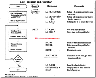
The flowchart is shown in Figure 8.9; blocks 5, 6, and 7 are identical to the blocks shown in Figure 8.7.

Program and Flowchart


Assembly Language Programming (Assembly Language Programming4)

Program Description and Execution

In this program, several labels are used to specify memory locations and I/O ports; this is a common industrial practice. When an assembler is used to write programs, labeling provides convenience and flexibility. In manual assembly, la­bels make it easy to read a program. In this problem, we need to specify or define absolute values of the labels SOURCE, OUTBUF, and PORTO, as well as the label START, the location where the program begins.

The flowchart in Figure is similar to the generalized flowchart of Figure 8.7. In the first block, registers HL and DE are used as memory pointers and register B as a counter to count ten bytes. In the next block, a byte is transferred from SOURCE memory to the accumulator using HL as the memory pointer, and the same byte is stored in OUTBUF memory using DE as the memory pointer.

The statements shown in the next block update the memory pointers and the counter. These statements may appear strange as algebraic equations; in fact, they are not algebraic statements but value assignments. The statement Count = Count – 1 means the new value is obtained by decrementing the previous value at the completion of one loop. It is important to remember that updating should be done before the decision making because once the Jump instruction finds that the Zero flag is not set, the program execution will go back to location NEXT. When the counter B is decremented to 0, the DEC B instruction sets the Zero flag. The program execution falls out of the loop and displays 01 at PORT0; this is shown as End in the flowchart.

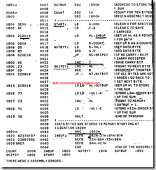
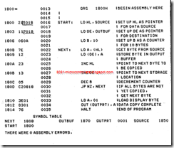
An example of the assembled program using an assembler is shown below. The assembler used is ZAD from CAMI Research, and the starting memory ad­dress is 1800H. In the following program, note that (1) instruction codes are shown on one line, (2) the memory addresses are skipped accordingly, and (3) the 16-bit numbers are entered in the reverse order, i.e., low order first, followed by high order. If you are assembling this program manually, you should ignore label definitions and assembler directives such as ORG.

Assembly Language Programming (Assembly Language Programming5)Assembly Language Programming (Assembly Language Programming6)


PROGRAMMING TECHNIQUES: LOOPING. COUNTING, AND INDEXJHG

PROGRAMMING TECHNIQUES: LOOPING. COUNTING, AND INDEXJHG

The examples illustrated in the previous sections are simple and can be solved manually. However, a computer is at its best, surpassing human capability, when it has to repeat such tasks as adding a large set of numbers or copying bytes from one block of memory locations to another. It is fast and accurate.

To perform a given repetitive task, commonly used techniques are looping, counting, and indexing. To add data bytes stored in memory, for example, the following steps are necessary.

I. Define the task to be repeated: Looping .

A loop is set up by using either a conditional Jump or an unconditional Jump as illustrated in Examples.

2. Specify how many times the task is to be repeated: Counting.

The counter is set by loading a count (number of times the task is to be re­peated) .into a register or a register pair, and the counting is done by decre­menting the count every time the loop is repeated. The counter can also be set up to count from 0 to the final count using increment instructions.

3. Specify the location of the data: Indexing.

The starting location of the data can be specified by loading the memory ad­dress into a register pair and using the register pair as a memory pointer or index.

4. Indicate the end of the repetitive task: Setting Flags.

The end of repetition is indicated by the flag of the conditional Jump instruc­tion. When the condition is true, the loop is repeated; when the condition is false, the loop execution is terminated, and the execution goes to the next instruction in memory.

Example

Draw a general flowchart to add ten bytes of data stored in memory starting at a given location, and display the sum. Explain the blocks in the flowchart.

Solution

To draw a flowchart, the problem must be divided into steps as follows:

1. Set up a counter to count the number of bytes.

Set up a memory pointer (index) to locate where data bytes are stored. Clear a register if necessary (either to store partial results or count the number of carries).

2. Transfer data from memory to the microprocessor.

3. Perform addition, checking for carry.

4. Save the partial result.

5. Update the counter and the memory pointer for the next operation.

6. Check the flag to indicate the completion of the task. If the condition is true repeat the task; otherwise go to the next instruction.

7. Display or store the result.

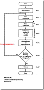
These steps and their sequence can be represented in the form of a flowchart as shown in Figure .

Blocks


Assembly Language Programming (Assembly Language Programming2)

1. Initialization

This is a planning stage where all initial conditions and requirements are defined. In our example, this block should set up a counter, memory index (pointer). carry register and temporary storage register.

2. Data Acquisition

Data are generally stored in memory or read from an input port. This step is con­cerned with bringing data into the mic­roprocessor.

3. Data Processing

This step involves data manipulation, such as arithmetic or logical operations. In the example, we add a data byte, check for a carry, and update the carry register if necessary.

4. Temporary Storage

This step involves storing of partial results so that the pfevious result will not be de­stroyed by the next data processing op­eration.

5. Getting Ready for Next Operation

Before we can check whether the task is completed, we need to update the initial conditions; the index and the counter should be incremented or decremented.

6. Decision Making

In this step, the flag is checked, if the con­dition is true, the loop is repeated; other­wise, the program goes to the next block to display the result.

7. Output

In this Block, the result is either sent to an output port or stored in memory.

LOOKING AHEAD

In the previous sections, we introduced three groups of instructions: data copy, arithmetic, and branching. These instructions were illustrated with examples. In the last section, we discussed the programming techniques with the generalized flowchart (Figure). Now we will illustrate two programs using the instructions and the programming techniques that were introduced and discussed. We will at­tempt to analyze the programming problems in terms of the blocks shown in Fig­ure and modify these blocks if necessary.


Z80 INSTRUCTIONS RELATED TO INDEX REGISTERS

Z80 INSTRUCTIONS RELATED TO INDEX REGISTERS


images

The Z80 microprocessor includes two 16-bit index registers IX and IY, and they are used primarily as memory pointers. In the previous sections, we discussed instructions concerning data copy, arithmetic, and branch operations. The Z80 can perform these operations with the contents of memory registers using the index registers.

The following group shows data copy, arithmetic, and unconditional jump instructions related to the IX registers; there is an identical set for the IY register.

Opcode

Operand

Bytes

Description

LD

IX, 16-bit

4

Load 16-bit data into IX register (this instruction was discussed in Section 8.1. l)

LD

(IX + d), 8-bit

4

Load 8-bit into memory location IX+ d

LD

r, (IX + d)

3

Copy from memory IX + d into register r

LD

(IX+ d), r

3

Copy from register r into memory IX+ d

ADD

A, (IX+ d)

3

Add contents of memory IX + d to A

SUB

(IX + d)

3

Subtract contents of memory IX + d from A

INC

IX

2

Increment 16-bit contents of IX

INC

(IX+ d)

3

Increment contents of memory IX + d

DEC

IX

2

Decrement 16-bit contents of IX

DEC

(IX+ d)

3

Decrement contents of memory IX+ d

General Characteristics

1. Index registers IX and IY are used as memory pointers. The memory address is calculated by adding the displacement byte (also known as offset) to the contents of the index register. The displacement byte is an 8-bit number; it can be either positive or negative. The magnitude of a positive offset is specified by the seven bits D6-D0, and the positive sign is indicated by bit D7 being 0.

For a negative offset, the displacement byte is expressed in 2’s complement (illustrated in Example). The total offset ranges from + 127 to -128 mem­ory locations.

2. When the operand is memory, it is specified by enclosing the memory address in the parentheses (as in any other memory-related instructions), and when the operand is the index register, it is written without parentheses.

3. The instructions listed above follow the same pattern as discussed in the pre­vious sections.

4. These instructions have 2-byte Opcodes; therefore, the number of bytes in index-related instructions ranges from two to four bytes.

Example 8.10

Set up index registers IX and IY as memory pointers to locations 2050H and 2185H, respectively. Load data bytes 32H into location 2090H and 97H into 2120H using the index registers. Add the bytes, and save the sum in the accumulator.

Solution

Mnemonics

Descriptions

LD IX, 2050H

;Point IX to location 2050H

LD IY, 2185H

;Point IY to location 2185H

LD (IX + 40H), 32H

;Load byte into location (2050H + 40H) = 2090H

LD (IY + 98H), 97H

;Load byte into location 2120H

Offset is (2185H – 2120H) 65H locations back­ward. 2’s complement of 65H = 9BH

LD A, (IX + 40H)

;Copy first byte (32H) into A

ADD A, (IY + 9BH)

;Add second byte

HALT

The memory addresses are calculated by adding the offset to the low-order byte of the index register.

IX+ 40 = 20 50

+40

————-

90H→2090H

IY + 9B = 21 85

+9B

——-

120

Complement CY → 020

Result→ 21 20H

Because the second operation is a 2’s complement addition, the carry is com­plemented.


Relative Jump Instructions

Relative Jump Instructions

The Z80 instruction set includes two types of relative Jump instructions: uncon­ditional and conditional. The new address to which the program sequence is re­directed is specified by an 8-bit offset (displacement) value relative to the Jump instruction. The displacement can be positive (forward jump), specified by the seven bits D6-D0 (the MSB D7 = 0), or negative (backward jump) specified in 2’s complement. The total offset values range from -126 to + 129 bytes. (explained in Example). The list of relative Jump instructions is (d = displacement).

Mnemonics

Bytes

Description

JR d

2

;Jump relative unconditionally

JR Z, d

2

;Jump relative if Z = 1

JR NZ, d

2

;Jump relative if Z =0

JR C, d

2

;Jump relative if CY =1

JR NC, d

2

;Jump relative if CY =0

Note: There are no relative Jump instructions based on Sign and Parity flags.

General Characteristics

1. These are 2-byte instructions; therefore, they are more efficient than 3-byte absolute jump instructions in terms of memory space and, in some situations, execution time.

2. Relative jumps are limited to 256 memory locations.

3. No flags are affected by these instructions.

Example

The unconditional relative Jump instruction is stored in memory locations 2100 and 2101H, as shown below. Find the memory address of the forward jump loca­tion if the displacement byte is 7FH. and find the memory address for the back­ward jump if the displacement byte is 9CH.


Assembly Language Programming (9)

Solution

1. When the jump instruction is executed, the program counter (PC) contains the .address 2102(PC always points to the next machine code to be fetched). By adding the displacement byte to the program counter, the address of the jump location becomes 2181H (2102H + 7FH).

For an 8-bit displacement byte, 7FH is the largest offset value for a for­ward jump. Therefore, relative to the memory location of the first code of the Jump instruction, the maximum displacement is 7FH plus two memory loca­tions of the instruction. The decimal equivalent of 81H (7F + 2) is 129; thus, the positive range extends to 129 memory locations.

2. If the displacement byte is 9CH, it is in 2’s complement because D7 = l. The memory address for the backward jump location from 2l02H (contents of the program counter) can be calculated two ways: (a) by adding the negative dis­placement 9CH or (b) by subtracting the positive displacement 64H, which is the 2’s c9mplement of 9CH. ·

(a)

(b)

Program Counter:

21 02

2 l

02

Displacement Byte:

+ 9C

6 4 2’s Complement of 9CH

In 2’s Complement:

9E

20 9E

Complement CY and:

1

9E

Subtract from 21":

20 9E

The memory address of the Jump location is 209EH. In the first calculation, after adding a negative number, the sum is 9EH without a carry. Therefore, in 2’s com­plement addition, the ninth bit must be set to l, indicating a borrow that is subtracted from 21H. If you are unfamiliar with 2’s complement arithmetic, review section B.2 in Appendix B. In the second calculation, 64H is a positive number obtained by taking 2’s complement of the negative number, and it is subtracted from 2102H.


BRANCH OPERATIONS

BRANCH OPERATIONS

The branch instructions and their associated flags are the key to the power of a computer or its microprocessor. These instructions can change the sequence of execution based on certain data conditions indicated by the flags; thus, they are decision-making instructions.

The branch instructions are classified into three categories, as listed in

Chapter 6: (1) Jump instructions, (2) Call and Return instructions, and (3) Restart instructions. In this chapter, we concentrate on Jump instructions.

Jump Instructions

The Jump instructions can be divided into two groups: absolute jump and relative jump. In case of absolute jump, the operand specifies the 16-bit address to which the program sequence should be transferred; these are 3-byte instructions. The relative jump instructions are 2-byte instructions and contain an operand that specifies 8-bit displacement, forward or backward (in 2’s complement), in relation to the address of the jump instruction; these instructions are discussed in the next section.

The absolute jump instructions can be further classified into two groups: unconditional and conditional jump. The conditional jump instructions are imple­mented based on the status of four flags: S (Sign), Z (Zero), CY (Carry), and P/V (Parity/Overflow). Two instructions are associated with each flag: one for when the flag is set and the other for when it is reset. The list of Jump instructions · follows:

Opcode

Operand

Bytes

Description

JP

16-bit

3

Jump unconditional to memory location specified by the 16-bit operand.

JP

C, 16-bit

3

Jump on carry to 16-bit address (CY = 1).

JP

NC, 16-bit

3

Jump on no carry to 16-bit address (CY = 0).

JP

16-bit

3

Jump on zero to 16-bit address (Z=1)

JP

NZ, 16-bit

3

Jump on no zero to 16-bit address (Z = 0)

JP

M, 16-bit 3

3

Jump on minus to 16-bit address (S =1).

JP

P, 16-bit

3

Jump on positive to 16-bit address (S = 0).

JP

PE, 16-bit

3

Jump on parity even to 16-bit address (P/V = 1).

JP

PO, 16-bit

3

Jump on parity odd to 16-bit address (P/V = 0).

General Characteristics

1. The Jump (JP) instructions are 3-byte instructions. The second byte specifies the low-order address, and the third byte specifies the high-order address.

2. A conditional jump instruction checks for the appropriate flag. If the condition is true, the program sequence is changed to the memory location specified by the operand; otherwise, the execution continues to the next instruction.

3. The Jump instructions do not affect any flags.

Example

Write instructions to load tow Hex bytes BYTE1 and BYTE2 into registers B and C, respectively, and add the bytes . If the sum is larger than 8 bits , display 00H as the overload condition at output port PORT1 , and clear the memory location OUTBUF ; otherwise , store the sun in memory location OUTBUF . Draw a flowchart , and assemble the program starting at location 2000H. the data bytes and the labels are defined as follows:

BYTEl = 9AH, BYTE2 = A7H, PORTl = 0lH, and OUTBUF = 2050H

Solution

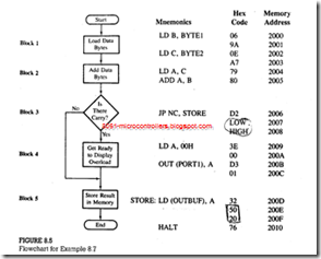
This problem is similar to Example, with some variations in display and data storage. A flowchart is shown in Figure. Each block in the flowchart is then translated into mnemonics, and-by looking up the instruction set, each mnemonic is converted into Hex code. The program should be assembled starting at location 2000H. The last column in Figure shows the corresponding memory addresses for each Hex code.

Program Description

1. In this program, data, bytes and memory locations are shown with labels; this is called symbolic representation. These symbols are defined generally in the beginning of a program. This is a common practice in writing assembly lan­guage programs, especially when using an assembler.

2. The first four instructions (mnemonics for blocks 1 and 2) are similar to those we used previously and need no additional explanation.

3. Block 3 is concerned with decision making, and it is important to understand how this block is translated into Hex code. If the ADD instruction generates a carry, the program follows the straight-line path; if it does not generate a carry,
Assembly Language Programming (7)

the program is branched. Initially, when we write the branch instruction (JP NC, STORE) for the decision-making block, we do not know the address of the jump location. Therefore, we just label the address as STORE and leave the two memory locations (2007Hand 2008H) for the address to be filled in later.

4. Now we can assemble the straight-line segment of the flowchart (blocks 4. and 5). The instructions shown in these blocks are self-explanatory. The criti­cal point to remember in entering memory addresses is that the 16-bit number is entered in the reversed order-low-order byte first, followed by the high order byte.

5. After completing the translation of blocks 4 and 5, we can specify the address of the Jump location STORE (200DH) and fill in the blanks for LOW and HIGH bytes; 0DH is entered in location 2007H, and 20H is entered in location 2008H.

Example

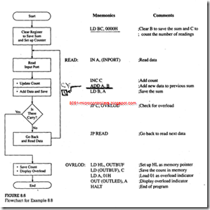
Write instructions to read incoming data from input port INPORT, count the num­ber of readings, and add the readings. When the sum exceeds FFH, stop reading the port, store the number of readings added in memory location OUTBUF, and display 01 at the output port OUTLED to indicate the overload.
Assembly Language Programming (8)

Program Description

1. This program uses two labels-READ AND OVRLOD-to specify jump mem­ory locations. Similarly, I/O ports are shown with labels: INPORT and OUTLED. To assemble this program, these labels must be replaced by appro­priate addresses.

2. Register B is used to save the sum, and register C is used to count the number of readings added.

3. Initially, registers B and C are cleared. If they are not cleared. In the first operation the sum and the count will have the residual contents of registers Band C.

4. The IN instruction reads the input port, and register C counts the number of data bytes read. The two following instructions add the data bytes and save the result in register B.

5. If the addition does not generate a carry. the READ loop is repeated. When the addition generates a carry, the microprocessor sets the CY flag to indicate an overload. The program jumps to location OVRLOD, whereby the count is saved in memory location OUTBUF, and the overload is indicated by display­ing 01H at the output port.