AC-AC transformer What It Does,How It Works,Variants,Values,How to Use it,What Can Go Wrong

What It Does

A transformer requires an input of alternating current (AC). It transforms the input voltage to one or more output voltages that can be higher or lower.

Transformers range in size from tiny impedance- matching units in audio equipment such as mi­crophones, to multi-ton behemoths that supply high voltage through the national power grids. Almost all electronic equipment that is designed to be powered by municipal AC in homes or busi­nesses requires the inclusion of a transformer.

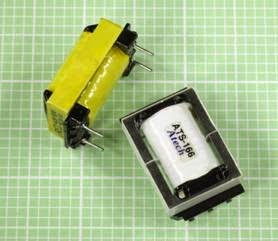
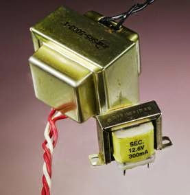
Two small power transformers are shown in Figure 15-1. The one at the rear is rated to provide 36VAC at 0.8A when connected with a source of 125VAC. At front, the miniature transformer is a Radio Shack product designed to provide ap­proximately 12VAC at 300mA, although its volt­ age will be more than 16VAC when it is not pass­ing current through a load.

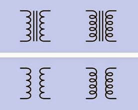
Transformer schematic symbols are shown in Figure 15-2. The different coil styles at left and right are functionally identical. Top: A transform­er with a magnetic core—a core that can be magnetized. Bottom: A transformer with an air core. (This type of transformer is rare, as it tends to be less efficient.) The input for the transformer is almost always assumed to be on the left, through the primary coil, while the output is on

clip_image004

Figure 15-1. Two small power transformers. The one at the rear measures approximately 1” × 2” × 2” and is rated to provide 36VAC at 0.8A. The term “sec” on the smaller unit is an abbreviation for “secondary,” referring to the rating for its secondary winding.

the right, through the secondary coil. Often the two coils will show differing numbers of turns to indicate whether the transformer is delivering a reduced voltage (in which case there will be few­er turns in the secondary coil) or an increased voltage (in which case there will be fewer turns in the primary coil).

clip_image007

Figure 15-2. Alternate symbols for a transformer with a ferromagnetic core (top) and air core (bottom). The differing coil symbols at left and right are functionally identi- cal.

How It Works

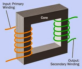
A simplified view of a transformer is shown in Figure 15-3. Alternating current flowing through the primary winding (orange) induces magnetic flux in a laminated core formed from multiple steel plates. The changing flux induces current in the secondary winding (green), which provides the output from the transformer. (In reality, the windings usually consist of thousands of turns of thin magnet wire, also known as enameled wire; and various different core configurations are used.)

The process is known as mutual induction. If a load is applied across the secondary winding, it will draw current from the primary winding, even though there is no electrical connection be­ tween them.

In an ideal, lossless transformer, the ratio of turns between the two windings determines whether the output voltage is higher, lower, or the same as the input voltage. If Vp and Vs are the voltages across the primary and secondary windings re­spectively, and Np and Ns are the number of turns of wire in the primary and secondary windings, their relationship is given by this formula:

Vp / Vs = Np / Ns


clip_image009

Figure 15-3. Three basic parts of a transformer, shown in simplified form.

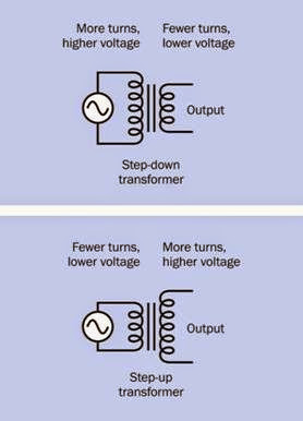
A simple rule to remember is that fewer turns = lower voltage while more turns = higher voltage.

A step-up transformer has a higher voltage at its output than at its input, while a step-down trans­ former has a higher voltage at its input than at its output. See Figure 15-4.

In an ideal, lossless transformer, the power input would be equal to the power output. If Vin and Vout are the input and output voltages, and Iin and Iout are the input and output currents, their rela­tionship is given by this formula:

Vin * Iin = Vout * Iout

Therefore, if the transformer doubles the voltage, it allows only half as much current to be drawn from the secondary winding; and if the voltage is cut in half, the available current will double.

Transformers are not 100% efficient, but they can be more than 98% efficient, and relationships between voltage, current, and the number of turns in the windings are reasonably realistic.

When the transformer is not loaded, the primary winding behaves like a simple inductor with re­ actance that inhibits the flow of current. There­ fore a power transformer will consume relatively

clip_image012

Figure 15-4. The ratio of input voltage to output voltage is equal to the ratio of primary turns to secondary turns in the transformer windings, assuming a transformer of 100% efficiency.

little electricity if it is left plugged in to an elec­trical outlet without any load connected to its output side. The power that it does consume will be wasted as heat.

The Core

The ferromagnetic core is often described as be­ing made of iron, but in reality is more often fab­ricated from high permeability silicon steel. To reduce losses caused by eddy currents, the core is usually laminated—assembled from a stack of plates separated from each other by thin layers of varnish or a similar insulator. Eddy currents tend to be constrained within the thickness of each plate.

Because a DC voltage would cause magnetic sat­uration of the core, all transformers must operate

with alternating current or pulses of current. The windings and geometry of a transformer are op­timized for the frequency range, voltage, and current at which it is designed to operate. Devi­ ating significantly from these values can damage the transformer.

Taps

A tap on a transformer is a connection part-way through the primary or (more often) the secon­dary coil. On the primary side, applying an input between the start of a coil and a tap part-way through the coil will reduce the number of turns to which the voltage is applied, therefore in­ creasing the ratio of output turns to input turns, and increasing the output voltage. On the sec­ ondary side, taking an output between the start of a coil and a tap part-way through the coil will reduce the number of turns from which the volt­ age is taken, therefore decreasing the ratio of output turns to input turns, and decreasing the output voltage. This can be summarized:

• A tap on the primary side can increase out­ put voltage.

• A tap on the secondary side can provide a decreased output voltage.

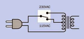
In international power adapters, a choice of input voltages may be allowed by using a double- throw switch to select either the whole primary winding, or a tapped subsection of the winding. See Figure 15-5. Modern electronics equipment often does not require a voltage adapter, be­ cause a voltage regulator or DC-DC convert­er inside the equipment will tolerate a wide range of input voltages while providing a rela­tively constant output voltage.

A transformer’s secondary winding is often tap­ped to provide a choice of output voltages. In fact, most power transformers have at least two outputs, since the cost of adding taps to the sec­ ondary winding is relatively small. As an

Chapter 15

clip_image015

Figure 15-5. An international power adapter can provide a fixed output voltage by using a double-throw switch to apply 230VAC voltage across a transformer’s primary winding, or 115VAC to a tapped midpoint of the primary winding.

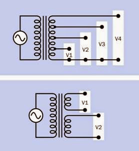
alternative to tapped outputs, two or more sep­arate secondary windings may be used, allowing the outputs to be electrically isolated from each other. See Figure 15-6.

clip_image017

Figure 15-6. Multiple output voltages may be obtained from a transformer by tapping into the secondary winding (top) or using two or more separate secondary windings (bottom), in which case the outputs will be electrically isolated from each other.

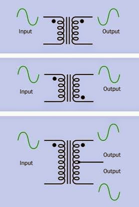
If the winding on the primary side of a trans­ former is coiled in the same direction as the winding on the secondary side, the output volt­ age will be 180 degrees out of phase with the

input voltage. In schematics, a dot is often placed at one end of a transformer coil to indicate where the coil begins. If the dots on the primary and secondary sides are at the same ends of the coils, there will be a 180 degree phase difference be­ tween input and output. For many applications (especially where the output from a power trans­ former is going to be converted to DC), this is immaterial.

If there is a center tap on the secondary winding, and it will be referenced as ground, the voltages relative to it, at opposite ends of the secondary winding, will be out of phase. See Figure 15-7.


Variants

Core Shapes

The shell core is a closed rectangle, as shown in Figure 15-3. This is the most efficient but most costly to manufacture. A C-shaped core is anoth­er option (three sides of the rectangle) and an E- I core is popular, consisting of a stack of E-shaped plates with two coils wound around the top and bottom legs of the E, or wound concentrically around the center leg of the E. An additional stack of straight plates is added to close the gaps in the E and form a magnetic circuit.

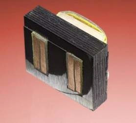
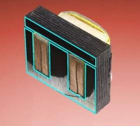
In Figure 15-8, the small transformer from Figure 15-1 has been sliced open with a band saw and a belt sander to reveal a cross-section of its windings. This clearly shows that its primary and secondary windings are concentric. It also re­veals the configuration of its core, which is in the E-I format. In Figure 15-9, the E-I configuration is highlighted to show it more clearly.

Power Transformer

Typically designed to be bolted onto a chassis or secured inside the case or cabinet housing a piece of electrical equipment with solder tabs or connectors allowing wires to connect the trans­ former to the power cord, on one side, and acir­

clip_image019

Figure 15-7. A dot indicates the start of each winding. Where primary and secondary windings are in the same direction, the voltage output will be 180 degrees out of phase with the input. Where the dots indicate windings in opposite directions, the voltage output will have the same phase as the input. Where a center tap on the secondary winding serves as a common ground, the voltages at opposite ends of the secondary winding will be opposite to each other in phase.

cuit board, on the other side. Smaller power transformers such as the one in Figure 15-1 have “through-hole” design with pins allowing them to be inserted directly onto circuit boards.

Plug-in Transformer

Usually sealed in a plastic housing that can be plugged directly into a wall power outlet. They are visually identical to AC adapters but have an AC output instead of a DC output.

clip_image021

Figure 15-8. The small transformer from the first figure in this entry is shown sliced open to reveal its internal config- uration.

clip_image023

Figure 15-9. The “EI” shaped plates that form the core of the transformer are outlined to show their edges.

Isolation Transformer

Also known as a 1:1 transformer because it has a 1:1 ratio between primary and secondary wind­ings, so that the output voltage will be the same as the input voltage. When electrical equipment is plugged into the isolation transformer, it is separated from the electrical ground of AC pow­er wiring. This reduces risk when working on

“live” equipment, as there will be negligible elec­trical potential between itself and ground. Con­sequently, touching a grounded object while al­ so touching a live wire in the equipment should not result in potentially lethal current passing through the body.

Autotransformer

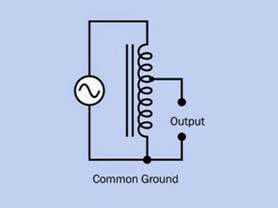
This variant uses only one coil that is tapped to provide output voltage. Mutual induction occurs between the sections of the coil. An autotrans­ former entails a common connection between its input and output, unlike a two-coil transform­ er, which allows the output to be electrically iso­lated from the input. See Figure 15-10. Auto­ transformers are often used for impedance matching in audio circuits, and to provide output voltages that differ only slightly from input vol­tages.

clip_image025

Figure 15-10. An autotransformer contains only one coil and core. A reduced output voltage can be obtained by tapping into the coil. A common connection prevents the output from being electrically isolated from the input.

Variable Transformer

A variable transformer, also known as a variac, resembles a wire-wound potentiometer. Only one winding is used. A wiper can be turned to contact the winding at any point, and serves as a movable tap. Like an autotransformer, a vari­able transformer entails a common connection between input and output.


Audio Transformer

When a signal is transmitted between two stages of a circuit that have different impedance, the signal may be partially reflected or attenuated. (Impedance is measured in ohms but is different from DC electrical resistance because it takes into account reactance and capacitance. It therefore varies with frequency.)

A device of low input impedance will try to draw significant current from a source, and if the source has high output impedance, its voltage will drop significantly as a result. Generally, the input impedance of a device should be at least 10 times the output impedance of the device that is trying to drive it. Passive components (re­sistors, and/or capacitors, and/or coils) can be used for impedance matching, but in some sit­uations a small transformer is preferable.

If Np and Ns are the number of turns of wire in the transformer primary and secondary windings, and Zp is the impedance of a device (such as an audio amplifier) driving the transformer on its primary side, and Zs is the impedance of a device (such as a loudspeaker) receiving power from the secondary side:

Np / Ns = √(Zp / Zs)

Suppose that an audio amplifier with rated out­ put impedance of 640Ω is driving a loudspeaker with 8Ω impedance. A matching transformer would be chosen with a ratio of primary turns to secondary turns give by:

√(640/8) = √80 = approximately 9:1

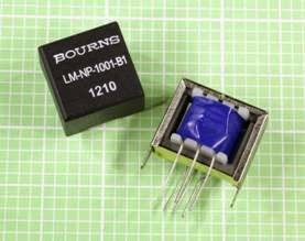
The two transformers in Figure 15-11 are through-hole components designed for tele­communications purposes, but are capable of passing audio frequencies and can be used for impedance matching in applications such as a preamplifier.

clip_image027

Figure 15-11. Through-hole transformers. See text for de- tails.

In Figure 15-12, the transformers are designed for audio coupling. The one on the right has impe­dances of 500 ohms (primary) and 8 ohms (sec­ondary). On the left is a fully encapsulated line matching transformer with a 1:1 turns ratio.

clip_image031

Figure 15-12. Through-hole transformers. See text for de- tails.

Split-Bobbin Transformer

This variant has primary and secondary coils mounted side by side to minimize capacitive coupling.

Surface-Mount Transformer

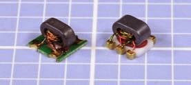
May be less than 0.2” square and is used for im­pedance matching, line coupling, and filtering. Two surface-mount transformers are shown in Figure 15-13.

clip_image029

Figure 15-13. Two surface-mount transformers, each measuring less than 0.2” square, typically used in communications equipment and suited for frequencies higher than 5 MHz.

Values

When selecting a power transformer, its power handling capability is the value of primary inter­ est. It is properly expressed by the term VA, de­ rived from “volts times amps.” VA should not be confused with watts because watts are measured instantaneously in a DC circuit, whereas in an AC circuit, voltage and current are fluctuating con­ stantly. VA is actually the apparent power, taking reactance into account.

The relationship between VA and watts will vary depending on the device under consideration. In a worst-case scenario:

W = 0.65 VA (approximately)

In other words, the averaged power you can draw from a transformer should be no less than two- thirds of its VA value.

Transformer specifications often include input voltage, output voltage, and weight of the com­ponent, all of which are self-explanatory. Cou­pling transformers may also specify input and output impedances.

How to Use it

For most electronic circuits, a power transformer will be followed by a rectifier to convert AC to DC, and capacitors to smooth fluctuations in the supply. Using a prepackaged power supply or AC adapter that already contains all the necessary components will be more time-effective and probably more cost-effective than building a power supply from the ground up. See Chap­ ter 16.

What Can Go Wrong

Reversal of Input and Output

Suppose a transformer is designed to provide an output voltage of 10 volts from domestic AC power of 115 volts. If the wrong side of the trans­

former is connected with 115VAC by mistake, the

output will now be more than 1,000 volts—easily enough to cause death, quite apart from de­stroying components that are connected with it. Reversing the transformer in this way may also destroy it. Extreme caution is advisable when making connections with power transformers. A meter should be used to check output voltage. All devices containing transformers should be fused on the live side and grounded.

Shock Hazard from Common Ground

When working on equipment that uses an auto­ transformer, the chassis will be connected through the transformer to one side of 115VAC power. So long as a plug is used that prevents reversed polarity, the chassis should be “neutral.” However, if an inappropriate power cord is used, or if the power outlet has been wired incorrectly, the chassis can become live. For protection, be­ fore working on any device that uses 115VAC power with an autotransformer, plug the device into an isolation transformer, and plug the isola­tion transformer into the wall outlet.


Accidental DC Input

If DC current is applied to the input side of a transformer, the relatively low resistance of the primary coil will allow high current that can de­ story the component. Transformers should only be used with alternating current.

Overload

If a transformer is overloaded, heat will be gen­erated that may be sufficient to destroy the thin layers of insulation between coil windings. Con­ sequently, input voltage can appear unexpect­ edly on the output side. Transformers with a tor­ oidal (circular) core are especially hazardous in this respect, as their primary and secondary windings usually overlap.

Some (not all) power transformers contain a ther­ mal fuse that melts when it exceeds a tempera­ture threshold. If the fuse is destroyed, the trans­ former must be discarded.

The consequences of moderate overloading may not be obvious, and can be cumulative over time. Ventilation or heat sinkage should be taken into account when designing equipment around a power transformer.

Incorrect AC Frequency

Single-phase AC power in the United States fluc­tuates at 60Hz, but Great Britain and some other countries use AC power at 50Hz. Many power transformers are rated to be compatible with ei­ther frequency, but if a transformer is specifically designed for 60Hz, it may eventually fail by over­ heating if it is used with a 50Hz supply. (A 50Hz transformer can be used safely with 60Hz AC.)
 

AC-DC power supply What It Does,How It Works,Variants,Values,How to Use it,What Can Go Wrong

Also known as an AC adapter. When packaged as a palm-sized plastic package that plugs directly into a power outlet, it is occasionally known colloquially as a wall-wart.

What It Does

An AC-DC power supply converts alternating cur­ rent (AC) into the direct current (DC) that most electronic devices require, usually at a lower volt­ age. Thus, despite its name, a power supply actually requires an external supply of power to operate.

Larger products, such as computers or stereo equipment, generally have a power supply con­tained within the device, enabling it to plug di­rectly into a wall outlet. Smaller battery-powered devices, such as cellular phones or media players, generally use an external power supply in the form of a small plastic pod or box that plugs into a wall outlet and delivers DC via a wire terminat­ing in a miniature connector. The external type of power supply is often, but not always, referred to as an AC adapter.

Although an AC-DC power supply is not a single component, it is often sold as a preassembled modular unit from component suppliers.

Variants

The two primary variants are a linear regulated power supply and switching power supply.


Linear Regulated Power Supply

A linear regulated power supply converts AC to DC in three stages:

1. A power transformer reduces the AC input to lower-voltage AC.

2. A rectifier converts the AC to unsmoothed DC. Rectifiers are discussed in the entry on diodes in this encyclopedia.

3. A voltage regulator, in conjunction with one or more capacitors, controls the DC voltage, smooths it, and removes transients. The regulator is properly known as a linear voltage regulator because it contains one or more transistors, which are functioning in linear mode—that is, responding linearly to fluctuations in base current, at less than their saturation level. The linear voltage regulator gives the linear regulated power supply its name.

A simplified schematic of a linear regulated pow­er supply is shown in Figure 16-1.

This type of power supply may be described as transformer-based, since its first stage consists of a transformer to drop the AC input voltage before it is rectified.

clip_image006

Figure 16-1. A basic linear regulated power supply.

Because the rectifier in a power supply generally passes each pulse of AC through a pair of silicon diodes, it will impose a voltage drop of about 1.2V at peak current. A smoothing capacitor will drop the voltage by about 3V as it removes ripple from the current, whereas a voltage regulator typically requires a difference of at least 2V be­ tween its input and its output. Bearing in mind also that the AC input voltage may fluctuate be­ low its rated level, the output from the power transformer should be at least 8VAC higher than the ultimate desired DC output. This excess power will be dissipated as heat.

The basic principle of the linear regulated power supply originated in the early days of electronic devices such as radio receivers. A transistorized version of this type of power supply remained in widespread use through the 1990s. Switching power supplies then became an increasingly at­ tractive option as the cost of semiconductors and their assembly decreased, and high-voltage tran­sistors became available, allowing the circuit to run directly from rectified line voltage with no step-down power transformer required.

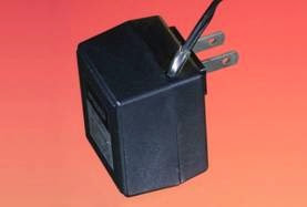
Some external AC adapters are still transformer- based, but are becoming a minority, easily iden­tified by their relatively greater bulk and weight. An example is shown in Figure 16-2.

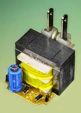
Figure 16-3 shows the handful of components inside a cheap, relatively old AC adapter. The out­

clip_image008

Figure 16-2. A simple transformer-based power supply can be encapsulated in a plastic shell, ready to plug into a power outlet. However, today this format more typically contains a switching power supply, which is usually light- er, smaller, and cheaper.

put from a power transformer is connected di­ rectly to four diodes (the small black cylinders), which are wired as a full-wave rectifier. A single electrolytic capacitor provides some smoothing, but because there is no voltage regulator, the output will vary widely depending on the load. This type of AC adapter is not suitable for powering any sensitive electronic equipment.

Switching Power Supply

Also known as a switched-mode power supply, an SMPS, or switcher, it converts AC to DC in two stages.

1. A rectifier changes the AC input to un­ smoothed DC, without a power transformer.

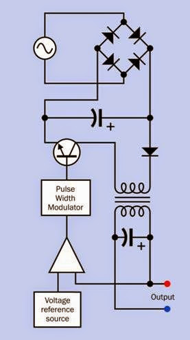
2. A DC-DC converter switches the DC on and off at a very high frequency using pulse- width modulation to reduce its average ef­fective voltage. Often the converter will be the flyback type, containing a transformer, but the high-frequency switching allows the transformer to be much smaller than the power transformer required in a linear regulated power supply. See the DC-DC con­verter entry in this encyclopedia for an ex­ planation of the working principles.

clip_image011

Figure 16-3. A relatively old, cheap AC adapter contains only the most rudimentary set of components, and does not supply the kind of properly regulated DC power re- quired by electronic equipment.

A simplified schematic of a switching power sup­ ply is shown in Figure 16-4.

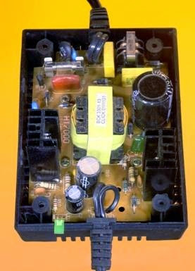
The interior of a relatively early switching power supply designed to deliver 12VDC at up to 4A is shown in Figure 16-5. This supply generated con­siderable waste heat, necessitating well-spaced components and a ventilated enclosure.

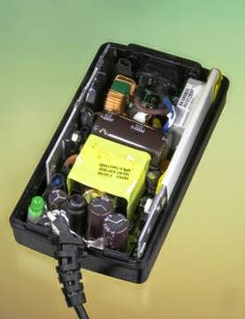
The type of small switching power supply that is now almost universally used to power laptop computers is shown in Figure 16-6. Note the smaller enclosure and the higher component count than in the older power supply shown in Figure 16-5. The modern unit also delivers con­siderably more power, and generates less waste heat. Although this example is rated at 5A, the

clip_image013Figure 16-4. Greatly simplified schematic showing the principal components of a switching power supply. Note the absence of a 115VAC power transformer. The trans- former that is inserted subsequently in the circuit functions in conjunction with the high switching frequency, which allows it to be very much smaller, cheaper, and lighter.

transformer (hidden under the yellow wrapper at the center of the unit) is smaller than the power transformer that would have been found in an old-style AC adapter delivering just 500mA.

The modern power supply is completely sealed, where earlier versions required ventilation. On


clip_image018Figure 16-5. The interior of an early switching power sup- ply.

the downside, the plastic case of the switching supply requires a metal liner (removed for this photograph) to contain high-frequency electro­ magnetic radiation.

Unregulated Power Supply

Typically this consists of a transformer and recti­fying diodes with little or no smoothing or volt­ age control of the output.

Adjustable Power Supply

This is usually a linear power supply incorporat­ing an adjustable voltage regulator. This type of supply has laboratory applications and is found as a benchtop item to power electronics design projects during their development.

 clip_image016

Figure 16-6. The interior of the type of switching power supply that powers a laptop computer.

Voltage Multiplier

Devices such as photocopiers and laser printers, televisions, cathode-ray tubes, and microwave ovens require voltages significantly higher than those supplied by domestic AC power outlets. A voltage multiplier usually contains a step-up transformer followed by DC conversion compo­nents, but detailed consideration is outside the scope of this encyclopedia.

Formats

An open frame power supply consists of compo­nents on a circuit board, usually mounted on a metal chassis, with no enclosure or fan cooling.

A covered power supply is enclosed in a protec­tive perforated metal box with a cooling fan if needed. Power supplies sold for desktop com­puters are usually in this format.

Power supplies are also available in rack-mount and DIN-rail formats.

How to Use it

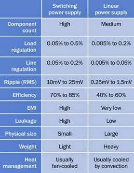
Because a switching power supply contains no power transformer, it is lighter and smaller, and may be cheaper than a linear power supply. It is also more efficient and generates less waste heat. These advantages have made switching power supplies the most popular option to provide DC power for electronics devices. However, the high- frequency switching tends to create electromag­netic interference (EMI), which must be filtered to protect the output of the device and also to min­imize the risk of this interference feeding back into AC power wiring. The high-frequency switched power may also generate harmonics, which must be suppressed.

High-quality linear regulated power supplies still find application in laboratory equipment, low- noise signal processing, and other niches where excellent regulation and low-ripple output are necessary. They are relatively heavy, bulky, and inefficient.

See Figure 16-7 for a chart comparing the ad­ vantages and disadvantages of linear and switching power supplies.

What Can Go Wrong
High Voltage Shock

One or more capacitors in a power supply may retain a relatively high voltage for some time af­ter the unit has been unplugged. If the power supply is opened for inspection or repairs, cau­ tion is necessary when touching components.

Capacitor Failure

If electrolytic capacitors fail in a switching power supply (as a result of manufacturing defects, dis­ use, or age), allowing straight-through conduc­tion of alternating current, the high-frequency switching semiconductor can also fail, allowing

input voltage to be coupled unexpectedly to the output. Capacitor failure is also a potential prob­lem in linear power supplies. For additional in­ formation on capacitor failure modes, see Chap­ ter 12.

clip_image020

Figure 16-7. Comparison of attributes of linear regulated power supplies and switching power supplies. (Adapted from Acopian Technical Company.)
Electrical Noise

If electrolytic capacitors are used, their gradual deterioration over time will permit more electri­cal noise associated with high-frequency switch­ ing in a switching power supply.

Peak Inrush

A switching power supply allows an initial inrush or surge of current as its capacitors accumulate their charge. This can affect other components in the circuit, and requires fusing that tolerates brief but large deviations from normal power consumption.


resistor What It Does,How It Works ,Variants,Values,How to Use it and What Can Go Wrong

What It Does

A resistor is one of the most fundamental com­ponents in electronics. Its purpose is to impede a flow of current and impose a voltage reduction. It consists of two wires or conductors attached at opposite ends or sides of a relatively poor elec­trical conductor, the resistance of which is meas­ured in ohms, universally represented by the Greek omega symbol, Ω.

Schematic symbols that represent a resistor are shown in Figure 10-1 (Left: The traditional sche­matic symbol. Right: The more recent European equivalent). The US symbol is still sometimes used in European schematics, and the European symbol is sometimes used in US schematics. Let­ters K or M indicate that the value shown for the resistor is in thousands of ohms or millions of ohms, respectively. Where these letters are used in Europe, and sometimes in the US, they are substituted for a decimal point. Thus, a 4.7K re­sistor may be identified as 4K7, a 3.3M resistor may be identified as 3M3, and so on. (The nu­meric value in Figure 10-1 was chosen arbitrarily.)

clip_image005

Figure 10-1. Resistor symbols. The left one is more common in the United States, while the right one is widely used in Europe. The 4.7K value was chosen arbitrarily.

A resistor is commonly used for purposes such as limiting the charging rate of a capacitor; pro­ viding appropriate control voltage to semicon­ductors such as bipolar transistors; protecting LEDs or other semiconductors from excessive current; adjusting or limiting the frequency re­sponse in an audio circuit (in conjunction with other components); pulling up or pulling down the voltage at the input pin of a digital logic chip; or controlling a voltage at a point in a circuit. In this last application, two resistors may be placed in series to create a voltage divider.

A potentiometer may be used instead of a re­sistor where variable resistance is required.

Sample resistors of various values are shown in Figure 10-2. From top to bottom, their power dis­sipation ratings are 3W, 1W, 1/2W, 1/4W, 1/4W, 1/4W, and 1/8W. The accuracy (tolerance) of each resistor, from top to bottom, is plus-or-minus 5%, 5%, 5%, 1%, 1%, 5%, and 1%. The beige-colored body of a resistor is often an indication that its tolerance is 5%, while a blue-colored body often indicates a tolerance of 1% or 2%. The blue- bodied resistors and the dark brown resistor con­tain metal-oxide film elements, while the beige- bodied resistors and the green resistor contain carbon film. For more information on resistor val­ues, see the upcoming Values section.

clip_image007

Figure 10-2. A range of typical resistors. See text for de- tails.

How It Works

In the process of impeding the flow of current and reducing voltage, a resistor absorbs electri­cal energy, which it must dissipate as heat. In most modern electronic circuits, the heat dissi­ pation is typically a fraction of a watt.

If R is the resistance in ohms, I is the current flowing through the resistor in amperes, and V is the voltage drop imposed by the resistor (the differ­ence in electrical potential between the two con­ tacts that are attached to it), Ohm’s law states:

V = I / R

This is another way of saying that a resistor of 1Ω will allow a current of 1 amp when the po­tential difference between the ends of the resis­tor is 1 volt.

If W is the power in watts dissipated by the resis­tor, in a DC circuit:

W = V * I

By substitution in Ohm’s law, we can express watts in terms of current and resistance:

W = I2 / R

We can also express watts in terms of voltage and resistance:

W = V2 * R

These alternates may be useful in situations where you do not know the voltage drop or the current, respectively.

Approximately similar relationships exist when using alternating current, although the power will be a more complex function.

Variants

Axial resistors have two leads that emerge from opposite ends of a usually cylindrical body. Ra­ dial resistors have parallel leads emerging from one side of the body and are unusual.

Precision resistors are generally defined as having a tolerance of no more than plus-or-minus 1%.

General-purpose resistors are less stable, and their value is less precise.

Power resistors are generally defined as dissipat­ing 1 or 2 watts or more, particularly in power supplies or power amplifiers. They are physically larger and may require heat sinks or fan cooling.

Wire-wound resistors are used where the compo­nent must withstand substantial heat. A wire- wound resistor often consists of an insulating tube or core that is flat or cylindrical, with multi­ple turns of resistive wire wrapped around it. The wire is usually a nickel-chromium alloy known as nichrome (sometimes written as Ni-chrome) and is dipped in a protecting coating.

The heat created by current passing through re­sistive wire is a potential problem in electronic circuits where temperature must be limited. However, in household appliances such as hair dryers, toaster ovens, and fan heaters, a ni­chrome element is used specifically to generate heat. Wire-wound resistors are also used in 3D printers to melt plastic (or some other com­ pound) that forms the solid output of the device.

Thick film resistors are sometimes manufactured in a flat, square format. A sample is shown in Figure 10-3, rated to dissipate 10W from its flat surface. The resistance of this component is 1K.

clip_image011

Figure 10-3. A thick-film resistor measuring about 1” square and 0.03” thick.

Surface-mount resistors generally consist of a re­sistive ink film printed on top of a tablet of alu­minum oxide ceramic compound, often approx­imately 6mm long, known as a 2512 form factor. Each surface-mount resistor has two nickel-

plated terminations coated in solder, which melts when the resistor is attached to the circuit board. The upper surface is coated, usually with black epoxy, to protect the resistive element.

Resistor Array

This is also known as a resistor network or resistor ladder, and consists of a chip containing multiple equal-valued resistors.

A resistor array in a single-inline package (or SIP) may have three possible internal configurations: isolated, common bus, and dual terminator. These options are shown at top, center, and bot­ tom, respectively, in Figure 10-4. The isolated variant is commonly available in SIPs with 6, 8, or 10 pins. The common-bus and dual-terminator configurations generally have 8, 9, 10, or 11 pins.

In the isolated configuration, each resistor is elec­trically independent of the others and is ac­cessed via its own pair of pins. On a common bus, one end of each resistor shares a bus accessed by a single pin, while the other ends of the resistors are accessed by their own separate pins. A dual- terminator configuration is more complex, con­sisting of pairs of resistors connected between ground and an internal bus, with the midpoint of each resistor pair accessible via a separate pin. The resistor pairs this function as voltage dividers and are commonly used in emitter-coupled logic circuits that require termination with -2 volts.

A dual-inline package (DIP) allows a similar range of internal configurations, as shown in Figure 10-5. At top, isolated resistors are com­monly available in DIPs with 4, 7, 8, 9, or 10 pins. At center, the common bus configuration is avail­ able in DIPs with 8, 14, 16, 18, or 20 pins. At bot­ tom, the dual-terminator configuration usually has 8, 14, 16, 18, or 20 pins.

The external appearance of SIP and DIP resistor arrays is shown in Figure 10-6. From left to right, the packages contain seven 120Ω resistors in

clip_image014

Figure 10-4. Multiple resistors can be embedded in a single-inline package (SIP) in a variety of formats. See text for additional details.

isolated configuration; thirteen 120Ω resistors in bussed configuration; seven 5.6K resistors in bussed configuration; and six 1K resistors in bussed configuration.

Resistor arrays with isolated or common-bus configurations are a convenient way to reduce the component count in circuits where pullup, pulldown, or terminating resistors are required for multiple chips. The common-bus configura­tion is also useful in conjunction with a 7-

clip_image016

Figure 10-5. Multiple resistors can be obtained embedded in a dual-inline package (DIP). See text for additional details.

segment LED display, where each segment must be terminated by a series resistor and all the resistors share a common ground or common voltage source.

Surface-mount chips are available containing a pair of resistors configured as a single voltage di­vider.

Chips containing multiple RC circuits (each consisting of a capacitor and a resistor in series) are available, although uncommon. A package containing a single RC circuit may be sold as a

clip_image018

clip_image020Figure 10-6. Resistor arrays in DIP and SIP packages. See text for values.

snubber to protect contacts in a switch or re­ lay that switches a large inductive load. More in­ formation on snubber circuits is in the capaci­ tor entry of this encyclopedia; see “Snubber” (page 108).

Values

1 kilohm, usually written as 1K, is 1,000Ω. 1 meg­ ohm, usually written as 1M or 1 meg, is 1,000K. 1 gig Naohm is 1,000 megs, although the unit is rarely used. Resistances of less than 1Ω are uncommon and are usually expressed as a decimal number followed by the Ω symbol. The term milliohms (thousandths of an ohm) is used in special appli­ cations. Equivalent resistor values are shown in Figure 10-7.

A resistance value remains unchanged in DC and AC circuits, except where the AC reaches an ex­tremely high frequency.

In common electronics applications, resistances usually range from 100Ω to 10M. Power ratings may vary from 1/16 watt to 1000 watts, but usu­ ally range from 1/8 watt to 1/2 watt in most elec­tronic circuits (less in surface-mount applica­tions).

Figure 10-7. Equivalent values in ohms, kilohms, and megohms.

Tolerance

The tolerance, or precision, of a resistor may range from plus-or-minus 0.001% up to plus-or- minus 20%, but is most commonly plus-or-minus 1%, 2%, 5%, or 10%.

The traditional range of resistor values was es­ tablished when a tolerance of 20% was the norm. The values were spaced to allow minimum risk of a resistor at one end of its tolerance range having the same value as another resistor at the oppo­ site end of its tolerance range. The values were rounded to 10, 15, 22, 33, 47, 68, and 100, as il­lustrated in Figure 10-8 where each blue dia­ mond represents the possible range of actual values of a 20% resistor with a theoretical value shown by the white horizontal line at the center of the diamond.

Resistor factors repeat themselves in multiples of

10. Thus, for example, beginning with a resistor of 100Ω, subsequent increasing values will be 150, 220, 330, 470, 680, and 1K, whereas the range of resistors beginning with 1Ω will be 1.5, 2.2, 3.3, 4.7, 6.8, and 10Ω.

Resistance multiplication factors are now ex­ pressed as a list of preferred values by the Inter­ national Electrotechnical Commission (IEC) in their 60063 standard. Intermediate factors have been added to the basic sequence to

clip_image022

Figure 10-8. Graphical representation of standard resistor values (white lines) established by the International Electrotechnical Commission, showing the acceptable range of actual values (dark blue areas) assuming precision of plus-or-minus 20%. The overlap, if any, between each range and the next is shown in black.

accommodate better tolerances. A table showing resistor values for tolerances of plus-or- minus 20%, 10%, and 5% appears in Figure 10-9. Resistors with a tolerance of 5% have become increasingly common.

clip_image024

Figure 10-9. Standard values for resistors of different precisions. For resistors outside the range shown, values can be found by multiplying or dividing (repeatedly, if necessary) by a factor of 10.

The IEC has established 3-digit preferred values for resistors with values accurate to plus-or- minus 0.5%.

Because many capacitors still have a tolerance no better than 20%, their values also conform with

the old original set of resistance values, although the units are expressed in farads or fractions of a farad. See the capacitors entry in this encyclo­pedia for additional information.

Value Coding

Through-hole axial resistors are traditionally printed with a sequence of three colored bands to express the value of the component, each of the first two bands representing a digit from 0 through 9, while the third band indicates the decimal multiplier (the number of zeroes, from 0 to 9, which should be appended to the digits). A fourth band of silver or gold indicates 10% or 5% tolerance respectively. No fourth band would in­dicate 20% tolerance, although this has become very rare.

Many resistors now have five color bands, to en­ able the representation of intermediate or frac­tional values. In this scheme, the first three bands have numeric values (using the same color sys­ tem as before) while the fourth band is the mul­tiplier. A fifth band, at the opposite end of the resistor, indicates its tolerance.

In Figure 10-10 the numeric or multiplier value of each color is shown as a “spectrum” at the top of the figure. The tolerance, or precision of a resistor, expressed as a plus-or-minus percentage, is shown using silver, gold, and various colors, at the bottom of the figure.

Two sample resistors are shown. The upper one has a value of 1K, indicated by the brown and black bands on the left (representing numeral 1 followed by a numeral 0) and the third red band (indicating two additional zeroes). The gold band at right indicates a precision of 5%. The lower one has a value of 1.05K, indicated by the brown, black, and green bands on the left (representing numeral 1 followed by numeral 0 followed by a numeral 5) and the fourth band brown (indicat­ing one additional zero). The brown band at right indicates a precision of 1%.

clip_image026

Figure 10-10. Color coding of through-hole resistors. See text for details.

In extremely old equipment, resistors may be co­ ded with the body-tip-dot scheme, in which the body color represents the initial digit, the end color represents the second digit, and a dot rep­ resents the multiplier. The numeric identities of the colors is the same as in the current color scheme.

In all modern schemes, the three or four bands that show the resistance value are spaced close together, while a larger gap separates them from the band that shows the tolerance. The resistor value should be read while holding the resistor so that the group of closely-spaced numeric bands is on the left.

Confusingly, some resistors may be found where the first three bands define the value, using the old three-band convention; the fourth band in­ dicates tolerance; and a fifth band at the oppo­ site end of the component indicates reliability. However, this color scheme is uncommon.

Other color-coding conventions may be found in special applications, such as military equipment.

It is common for through-hole carbon-film resis­tors to have a beige body color, while through- hole metal-film resistors often have a blue body color. However, in relatively rare instances, a blue body color may also indicate a fusible resistor (designed to burn out harmlessly like a fuse, if it is overloaded) while a white body may indicate a non-flammable resistor. Use caution when re­ placing these special types.

Some modern resistors may have their values printed on them numerically. Surface-mount re­sistors also have digits printed on them, but they are a code, not a direct representation of resist­ ance. The last digit indicates the number of ze­roes in the resistor value, while the preceding two or three numbers define the value itself. Let­ter R is used to indicate a decimal point. Thus a 3R3 surface-mount resistor has a value of 3.3Ω, while 330 would indicate 33Ω, and 332 indicates 3,300Ω. A 2152 surface-mount resistor would have a value of 21,500Ω.

A surface-mount resistor with a single zero print­ed on it is a zero ohm component that has the same function as a jumper wire. It is used for convenience, as it is easily inserted by automated production-line equipment. It functions merely as a bridge between traces on the circuit board.

When resistor values are printed on paper in schematics, poor reproduction may result in omission of decimal points or introduction of specks that look like decimal points. Europeans have addressed this issue by using the letter as a substitute for a decimal point so that a 5.6K re­sistor will be shown as 5K6, or a 3.3M resistor will be shown as 3M3. This practice is followed infre­ quently in the United States.

Stability

This term describes the ability of a resistor to maintain an accurate value despite factors such as temperature, humidity, vibration, load cycling, current, and voltage. The temperature coeffi­ cient of a resistor (often referred to as Tcr or Tc, not to be confused with the time constant of a charg­ing capacitor) is expressed in parts per million

change in resistance for each degree centigrade deviation from room temperature (usually as­sumed to be 25 degrees Centigrade). Tcmay be a positive or a negative value.

The voltage coefficient of resistance—often ex­ pressed as Vc—describes the change of a resis­tor’s value that may occur as a function of changes in voltage. This is usually significant only where the resistive element is carbon-based. If V1 is the rated voltage of the resistor, R1 is its rated resistance at that voltage, V2 is 10% of the rated voltage, and R2 is the actual resistance at that voltage, the voltage coefficient, Vc, is given by this formula:

Vc = (100 * (R1 – R2)) / (R2 * (V1 – V2))

Materials

Resistors are formed from a variety of materials.

Carbon composite. Particles of carbon are mixed with a binder. The density of the carbon deter­ mines the end-to-end resistance, which typically ranges from 5Ω to 10M. The disadvantages of this system are low precision (a 10% tolerance is common), relatively high voltage coefficient of re­ sistance, and introduction of noise in sensitive circuits. However, carbon-composite resistors have low inductance and are relatively tolerant of overload conditions.

Carbon film. A cheap and popular type, made by coating a ceramic substrate with a film of carbon compound. They are available in both through- hole and surface-mount formats. The range of resistor values is comparable with carbon- composite types, but the precision is increased, typically to 5%, by cutting a spiral groove in the carbon-compound coating during the manufac­ turing process. The carbon film suffers the same disadvantages of carbon composite resistors, but to a lesser extent. Carbon film resistors gen­ erally should not be substituted for metal film resistors in applications where accuracy is im­portant.

Metal film. A metallic film is deposited on a ce­ ramic substrate, and has generally superior char­

acteristics to carbon-film resistors. During man­ ufacture, a groove may be cut in the metal film to adjust the end-to-end resistance. This may cause the resistor to have higher inductance than carbon-composite types, though it has lower noise. Tolerances of 5%, 2%, and 1% are available. This type of resistor was originally more expen­ sive than carbon-film equivalents, but the differ­ ence is now fractional. They are available in both through-hole and surface-mount formats. They are available in lower-wattage variants (1/8 watt is common).

Thick-film resistors are spray-coated, whereas thin-film resistors are sputtered nichrome. Thin- films enjoy a flatter temperature coefficient and are typically used in environments that have a huge operational temperature range, such as satellites.

Bulk metal foil. The type of foil used in metal film resistors is applied to a ceramic wafer and etched to achieve the desired overall resistance. Typical­ ly these resistors have axial leads. They can be extremely accurate and stable, but have a limited maximum resistance.

Precision wire-wound. Formerly used in applica­tions requiring great accuracy, but now largely replaced by precision metal foil.

Power wire-wound. Generally used when 1 or 2 watts or more power dissipation is required. Re­sistive wire is wrapped around a core that is often ceramic. This can cause the resistor to be referred to, inaccurately, as “ceramic.” The core may alter­ natively be fiberglass or some other electrically insulating compound that actively sinks heat. The component is either dipped (typically in vit­reous enamel or cement) or is mounted in an aluminum shell that can be clamped to a heat sink. It almost always has the ohm value printed on it in plain numerals (not codes).

Two typical wire-wound resistors are shown in Figure 10-11. The upper resistor is rated at 12W and 180Ω while the lower resistor is rated at 13W and 15K.

clip_image028

Figure 10-11. Two wire-wound resistors of greatly differ- ing resistance but similar power dissipation capability.

A larger wire-wound resistor is shown in

Figure 10-12, rated for 25W and 10Ω.

clip_image030

Figure 10-12. A large wirewound resistor rated to dissipate 25W.

In Figure 10-13, two resistors encapsulated in ce­ment coatings are shown with the coatings re­ moved to expose the elements. At left is a 1.5Ω 5W resistor, which uses a wire-wound element. At right is a very low-value 0.03Ω 10W resistor.

clip_image032

Figure 10-13. Two low-value resistors with their cement coatings removed to show the resistive elements.

In Figure 10-14, the resistor at right has an ex­ posed 30Ω element while the resistor at left is rated 10W and 6.5Ω, enclosed in an anodized aluminum shell to promote heat dissipation.

clip_image034

Figure 10-14. A 30Ω resistor (right) and 6.5Ω resistor (left).

In power resistors, heat dissipation becomes an important consideration. If other factors (such as voltage) remain the same, a lower-value resistor will tend to pass more current than a higher- value resistor, and heat dissipation is proportion­ al to the square of the current. Therefore power wire-wound resistors are more likely to be need­ed where low resistance values are required. Their coiled-wire format creates significant in­ductance, making them unsuitable to pass high frequencies or pulses.

How to Use it

Some of the most common applications for a re­sistor are listed here.

In Series with LED

To protect an LED from damage caused by ex­cessive current, a series resistor is chosen to allow a current that does not exceed the manufactur­er’s specification. In the case of a single through- hole LED (often referred to as an indicator), the forward current is often limited to around 20mA, and the value of the resistor will depend on the voltage being used. (See Figure 10-15.)

When using high-output LEDs (which may con­tain multiple elements in a single 5mm or 10mm package), or LED arrays that are now being used for domestic lighting, the acceptable current may be much greater, and the LED unit may con­tain its own current-limiting electronics. A data­ sheet should be consulted for details.

clip_image036

Figure 10-15. A series resistor is necessary to limit the current that passes through an LED.

Current Limiting with a Transistor In Figure 10-16, a transistor is switching or am­ plifying current flowing from B to C. A resistor is used to protect the base of the transistor fromexcessive current flowing from point A. Resistorsare also commonly used to prevent excessive current from flowing between B and C.

clip_image040


Figure 10-16. A resistor is typically necessary to protect the base of a transistor from excessive current.

Pullup and Pulldown Resistors

When a mechanical switch or pushbutton is at­ tached to the input of a logic chip or microcon­ troller, a pullup or pulldown resistor is used, ap­ plying positive voltage or grounding the pin, re­ spectively, to prevent it from “floating” in an in­ determinate state when the switch is open. In Figure 10-17, the upper schematic shows a pull­ down resistor, whereas the lower schematic shows a pullup resistor. A common value for ei­ther of them is 10K. When the pushbutton is pressed, its direct connection to positive voltage or to ground easily overwhelms the effect of the resistor. The choice of pullup or pulldown resistor may depend on the type of chip being used.

Audio Tone Control

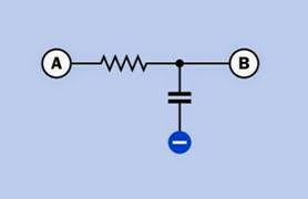
A resistor-capacitor combination can limit the high-frequency in a simple audio tone-control circuit, as shown in Figure 10-18. Beneath a signal travelling from A to B, a resistor is placed in series with a capacitor that passes high frequencies to ground. This is known as a low-pass filter.

RC Network

A resistor will adjust the charge/discharge time when placed in series with a capacitor, as in Figure 10-19. When the switch closes, the resistor limits the rate at which the capacitor will charge itself from the power supply. Because a capacitor has an ideally infinite resistance to DC current, the voltage measured at point A will rise until it

clip_image038

Figure 10-17. A pulldown resistor (top) or pullup resistor (bottom) prevents an input pin on a logic chip or micro- controller from “floating” in an indeterminate state when the button is not being pressed.
clip_image042

Figure 10-18. This configuration may be used to remove high frequencies from an audio signal. It is known as a low-pass filter because low frequencies are passed from A to B.

is close to the supply voltage. This is often re­ferred to as an RC (resistor-capacitor) network and is discussed in greater detail in the capacitor section of this encyclopedia.

clip_image044

Figure 10-19. In an RC (resistor-capacitor) network, a resistor limits the rate of increase in potential of the capaci- tor, measured at A, when the switch is closed.

Voltage Divider

Two resistors may be used to create a voltage di­vider (see Figure 10-20). If Vin is the supply volt­ age, the output voltage, Vout, measured at point A, is found by the formula:

Vout = Vin * (R2 / (R1 + R2))

In reality, the actual value of Vout is likely to be affected by how heavily the output is loaded.

If the output node has a high impedance, such as the input to a logic chip or comparator, it will be more susceptible to electrical noise, and lower-value resistors may be needed in the volt­ age divider to maintain a higher current flow and maintain stability in the attached device.

Resistors in Series

If resistors in series have values R1, R2, R3 . . . the total resistance, R, is found by summing the in­ dividual resistances:

clip_image046

Figure 10-20. In a DC circuit, a pair of resistors may be placed in series to function as a voltage divider. The volt- age measured at A will be lower than the supply voltage, but above ground potential.

R = R1 + R2 + R3. . .

The current through each of the resistors will be the same, whereas the voltage across each of them will vary proportionately with its resist­ance. If the supply voltage across the series of resistors is VS, and the total of all the resistor val­ues is RT, and the resistance of one resistor is R1, the voltage across that resistor, V1, will be given by the formula:

V1 = VS * (R1 / RT)

Resistors in Parallel

Where two or more resistors (R1, R2, R3 . . . ) are wired in parallel, their total resistance, R, is found from the formula:

1/R = ( 1/R1 ) + ( 1/R2 ) + ( 1/R3 ). . .

Suppose that R1, R2, R3 . . . all have the same in­ dividual resistance, represented by RI, and the number of resistors is N. Their total resistance, RT, when wired in parallel, will be:

RT = RI / N

If each resistor has an equal resistance and also has an equal individual rating in watts (repre­sented by WI), the total wattage (WT) that they can handle when wired in parallel to share the power will be:

WT = WI * N

Therefore, if an application requires high- wattage resistors, multiple lower-wattage, higher-value resistors may be substituted if they are wired in parallel—and may even be cheaper than a single high-wattage wire-wound resistor. For example, if a 5W, 50Ω resistor is specified, 10 resistors can be substituted, each rated at 0.5W and 500Ω. Bear in mind that if they are tightly bundled, this will interfere with heat dissipation.

What Can Go Wrong
Heat

Resistors are probably the most robust of all elec­tronic components, with high reliability and a long life. It is difficult to damage a resistor by overheating it with a soldering iron.

The wattage rating of a resistor does not neces­sarily mean that it should be used to dissipate that amount of power on a constant basis. Small resistors (1/4 watt or less) can overheat just as easily as big ones. Generally speaking, it is safe practice not to exceed 75% of a resistor’s power rating on a constant basis.

Overheating is predictably more of a problem for power resistors, where provision must be made for heat dissipation. Issues such as component crowding should be considered when deciding how big a heat sink to use and how much venti­lation. Some power resistors may function relia­bly at temperatures as high as 250 degrees Cen­ tigrade, but components near them are likely to be less tolerant and plastic enclosures may soft­ en or melt.

Noise

The electrical noise introduced by a resistor in a circuit will vary according to the composition of

the resistor, but for any given component, it will be proportional to voltage and current. Low- noise circuits (such as those at the input stage of a high-gain amplifier) should use low-wattage resistors at a low voltage where possible.

Inductance

The coiled wire of a wire-wound resistor will be significantly inductive at low frequencies. This is known as parasitic inductance. It will also have a resonant frequency. This type of resistor is un­ suitable for applications where frequency ex­ ceeds 50KHz.

Inaccuracy

When using resistors with 10% tolerance, impre­cise values may cause greater problems in some applications than in others. In a voltage divider, for instance, if one resistor happens to be at the high end of its tolerance range while the other happens to be at the low end, the voltage ob­tained at the intersection of the resistors will vary from its expected value. Using the schematic shown in Figure 10-20, if R1 is rated for 1K and R2 is rated for 5K, and the power supply is rated at 12VDC, the voltage at point A should be:

V = 12 * (( 5 / (5 + 1)) = 10

However, if R1 has an actual value of 1.1K and R2 has an actual value of 4.5K, the actual voltage obtained at point A will be:

V = 12 * (( 4.5 / (4.5 + 1.1)) = 9.6

If the resistors are at opposite ends of their re­ spective tolerance ranges, so that R1 has an ac­tual value of 900Ω while the lower resistor has an actual value of 5.5K, the actual voltage obtained will be:

V = 12 * (( 5.5 / (5.5 + 0.9)) = 10.3

The situation becomes worse if the two resistors are chosen to be of equal value, to provide half of the supply voltage (6 volts, in this example) at their intersection. If two 5K resistors are used, and the upper one is actually 4.5K while the lower one is 5.5K, the actual voltage will be:

V = 12 * (( 5.5 / (4.5 + 5.5)) = 6.6

Whether this variation is significant will depend on the particular circuit in which the voltage di­vider is being used.

Common through-hole resistors may occasion­ ally turn out to have values that are outside their specified tolerance range, as a result of poor manufacturing processes. Checking each resis­ tor with a meter before placing it in a circuit should be a standard procedure.

When measuring the voltage drop introduced by a resistor in an active circuit, the meter has its own internal resistance that will take a propor­ tion of the current. This is known as meter load­ ing and will result in an artificially low reading for

the potential difference between the ends of a resistor. This problem becomes significant only when dealing with resistors that have a high val­ ue (such as 1M), comparable with the internal resistance of the meter (likely to be 10M or more).

Wrong Values

When resistors are sorted into small bins by the user, errors may be made, and different values may be mixed together. This is another reason for checking the values of components before using them. Identification errors may be nontrivial and easily overlooked: the visible difference between a 1 megohm resistor and a 100Ω resistor is just one thin color band.


variable capacitor What It Does,How It Works,Variants,Values,How to Use it,What Can Go Wrong

Formerly known (primarily in the United Kingdom) as a variable condenser. The term is now obsolete.

What It Does

A variable capacitor allows adjustment of capac­itance in much the same way that a potentiom­eter allows adjustment of resistance.

Large variable capacitors were developed pri­marily to tune radio receivers, in which they were known as tuning capacitors. Cheaper, simpler, and more reliable substitutes gradually dis­ placed them, beginning in the 1970s. Today, they are still used in semiconductor fabrication, in RF plastic welding equipment, in surgical and den­ tal tools, and in ham radio equipment.

Small trimmer capacitors are widely available and are mostly used to adjust high-frequency cir­cuits. Many of them look almost indistinguisha­ble from trimmer potentiometers.

The schematic symbols commonly used to rep­ resent a variable capacitor and a trimmer capac­itor are shown in Figure 13-1.

A varactor is a form of diode with variable capac­itance, controlled by reverse voltage. See “Var­ actor Diode” (page 225) for this component.

How It Works

The traditional form of variable capacitor con­sists of two rigid semicircular plates separated by an air gap of 1mm to 2mm. To create more ca­

clip_image004

Figure 13-1. Typical schematic symbols for variable capacitor (left) and trimmer capacitor (right).

pacitance, additional interleaved plates are add­ed to form a stack. One set of plates is known as the rotor, and is mounted on a shaft that can be turned, usually by an externally accessible knob. The other set of plates, known as the stator, is mounted on the frame of the unit with ceramic insulators. When the sets of plates completely overlap, the capacitance between them is maxi­mized. As the rotor is turned, the sets of plates gradually disengage, and the capacitance dimin­ishes to near zero. See Figure 13-2.

The air gaps between the sets of plates are the dielectric. Air has a dielectric constant of approx­imately 1, which does not vary significantly with temperature.

The most common shape of plate is a semicircle, which provides a linear relationship between ca­pacitance and the angle of rotation. Other shapes have been used to create a nonlinear re­sponse.

clip_image007

Figure 13-2. In this simplified view of a variable capacitor, the brown plates constitute the rotor, attached to a central shaft, while the blue plates are the stator. The colors have no electrical significance and are added merely for clarity. The area of overlap between rotor and stator determines the capacitance.

Reduction gears may be used to enable fine tun­

Figure 13-3. A “traditional style” variable capacitor of the type designed to tune radio frequencies. The spring, circled, enables anti-backlash gearing.


ing of a variable capacitor, which means multiple

turns of a knob can produce very small adjust­ ments of the capacitor. At the peak of variable capacitor design, units were manufactured with high mechanical precision and included anti- backlash gears. These consisted of a pair of equal- sized gears mounted flat against each other with a spring between them that attempted to turn the gears in opposite directions from each other. The pair of gears meshed with a single pinion, eliminating the looseness, or backlash, that nor­mally exists when gear teeth interlock. A vintage capacitor with a spring creating anti-backlash gearing (circled) is shown in Figure 13-3. This is a two-gang capacitor—it is divided into two sec­tions, one rated 0 to 35pF, the other rated 0 to 160pF.

clip_image009

Variants

The traditional variable capacitor, with exposed, air-spaced, rigid, rotating vanes, is becoming hard to find. Small, modern variable capacitors are entirely enclosed, and their plates, or vanes, are not visible. Some capacitors use a pair of con­ centric cylinders instead of plates or vanes, with an external thumb screw that moves one cylin­der up or down to adjust its overlap with the other. The overlap determines the capacitance.

Trimmer capacitors are available with a variety of dielectrics such as mica, thin slices of ceramic, or plastic.

Values

A large traditional capacitor can be adjusted down to a near-zero value; its maximum will be no greater than 500pF, limited by mechanical factors. (See Chapter 12 for an explanation of ca­pacitance units.)

A maximum value for a trimmer capacitor is sel­dom greater than 150pF. Trimmers may have their values printed on them or may be color- coded, but there is no universal set of codes. Brown, for example, may indicate either a maxi­ mum value around 2pF or 40pF, depending on the manufacturer. Check datasheets for details.

The upper limit of a trimmer’s rated capacitance is usually no less than the rated value, but can often be 50% higher.

Formats

All trimmer capacitors are designed for mount­ ing on circuit boards. Many are surface-mount, with a minority being through-hole. Surface- mount units may be 4mm × 4mm or smaller. Through-hole are typically 5mm × 5mm or larger. Superficially, trimmer capacitors resemble single-turn trimmer potentiometers with a screw head in the center of a square package. A through-hole example is shown in Figure 13-4.

clip_image012

Figure 13-4. A trimmer capacitor rated 1.5pF to 7.0pF.


How to Use it

A variable capacitor is often used to tune an LC circuit, so called because a coil (with reactance customarily represented by letter L) is wired in parallel with a variable capacitor (represented by letter C). The schematic in Figure 13-5 shows an imaginary circuit to illustrate the principle. When the switch is flipped upward, it causes a large fixed-value capacitor to be charged from a DC power source. When the switch is flipped down, the capacitor tries to pass current through the coil—but the coil’s reactance blocks the current and converts the energy into a magnetic field. After the capacitor discharges, the magnetic field collapses and converts its energy back into elec­tricity. This flows back to the capacitor, but with inverted polarity. The cycle now repeats with current flowing in the opposite direction. A low- current LED across the circuit would flash as the voltage oscillates, until the energy is exhausted.

clip_image015

Figure 13-5. In this imaginary circuit, the capacitor is charged through the double-pole switch in its upper posi- tion. When the switch is turned, the capacitor forms an LC (inductance-capacitance) circuit with the coil, and reso- nates at a frequency determined by their values. In reality, extremely high values would be needed to obtain a visible result from the LED.

Because the oscillation resembles water sloshing from side to side in a tank, an LC circuit is some­ times referred to as a tank circuit.

In reality, unrealistically large values would be required to make the circuit function as de­ scribed. This can be deduced from the following formula, where f is the frequency in Hz, L is in­ductance in Henrys, and C is capacitance in Far­ ads:

f = 1 / (2π * √(L * C) )

For a frequency of 1Hz, a massive coil opposite a very large capacitor of at least 0.1F would be needed.

However, an LC circuit is well-suited to very high frequencies (up to 1,000MHz) by using a very small coil and variable capacitor. The schematic in Figure 13-6 shows a high-impedance ear­ phone and a diode (right) substituted for the LED and the resistor in the imaginary circuit, while a variable capacitor takes the place of the fixed ca­pacitor. With the addition of an antenna at the top and a ground wire at the bottom, this LC cir­cuit is now capable of receiving a radio signal, using the signal itself as the source of power. The resonant frequency of the circuit is tuned by the variable capacitor. The impedance peaks at the resonant frequency, causing other frequences to be rejected by passing them to ground. With suitable refinement and amplification, the basic principle of an LC circuit is used in AM radios and transmitters.

Because variable capacitors are so limited in size, they are unsuitable for most timing circuits.

Trimmer capacitors are typically found in high- power transmitters, cable-TV transponders, cel­lular base stations, and similar industrial appli­cations.

They can be used to fine-tune the resonant fre­quency of an oscillator circuit, as shown in Figure 13-7.

clip_image018

Figure 13-6. The principle of an LC circuit is used here in a basic circuit that can tune in to a radio station and cre- ate barely audible sound through the earphone at right, using only the broadcast signal for power. The variable ca- pacitor adjusts the frequency of the circuit to resonate with the carrier wave of the radio signal.

clip_image020

Figure 13-7. A trimmer capacitor in series with a crystal fine-tunes the frequency of this basic circuit using an op- amp.

In addition to tuning a circuit frequency, a trim­mer capacitor can be used to compensate for changes in capacitance or inductance in a circuit that are caused by the relocation of wires or re­ routing of traces during the development pro­cess. Readjusting a trimmer is easier than swap­ ping fixed-value capacitors. A trimmer may also be used to compensate for capacitance in a cir­cuit that gradually drifts with age.

What Can Go Wrong

Failure to Ground Trimmer Capacitor While Adjusting it Although trimmer capacitors are not polarized, the manufacturer may mark one terminal with a

plus sign and/or the other with a minus sign. If

the capacitor is adjusted while its negative ter­minal is floating or ungrounded, a metal screw­ driver blade will create erroneous readings. Al­ ways ground the appropriate side of a trimmer capacitor before fine-tuning it, and preferably use a plastic-bladed screwdriver.

Application of Overcoat Material or “Lock Paint”

Overcoat material is a rubbery adhesive that may be spread over assembled components to im­munize them against moisture or vibration. Lock paint is a dab of paint that prevents a screw ad­justment from turning after it has been set. Most manufacturers advise against applying these materials to a trimmer capacitor, because if pen­etration occurs, the capacitor can fail.

Lack of Shielding

Variable capacitors should be shielded during use, to protect them from external capacitive ef­fects. Merely holding one’s hand close to a vari­able capacitor will change its value.


potentiometer What It Does,How It Works,Variants,Values,How to Use it,What Can Go Wrong

Also known as a variable resistor; may be substituted for a rheostat.

What It Does

When a voltage is applied across a potentiome­ter, it can deliver a variable fraction of that volt­ age. It is often used to adjust sensitivity, balance, input, or output, especially in audio equipment and sensors such as motion detectors.

A potentiometer can also be used to insert a vari­able resistance in a circuit, in which case it should really be referred to as a variable resistor, al­ though most people will still call it a potentiometer.

It can be used to adjust the power supplied to a circuit, in which case it is properly known as a rheostat, although this term is becoming obso­lete. Massive rheostats were once used for pur­ poses such as dimming theatrical lighting, but solid-state components have taken their place in most high-wattage applications.

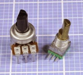
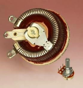
A full-size, classic-style potentiometer is shown in Figure 11-1.

Schematic symbols for a potentiometer and oth­er associated components are shown in Figure 11-2, with American versions on the left and European versions on the right in each case. The symbols for a potentiometer are at the top. The correct symbols for a variable resistor or rheostat are shown at center, although a poten­tiometer symbol may often be used instead. A

clip_image004

Figure 11-1. A generic or classic-style potentiometer, ap- proximately one inch in diameter.

preset variable resistor is shown at the bottom, often referred to as a trimmer or Trimpot. In these examples, each has an arbitrary rated resistance of 4,700Ω. Note the European substitution of K for a decimal point.

clip_image007

Figure 11-2. American (left) and European (right) symbols for a potentiometer, a rheostat, and a trimmer potentiometer, reading from top to bottom. The 4.7K value was chosen arbitrarily.

How It Works

A potentiometer has three terminals. The outer pair connect with the opposite ends of an inter­ nal resistive element, such as a strip of conduc­tive plastic, sometimes known as the track. The third center terminal connects internally with a contact known as the wiper (or rarely, the pick- off), which touches the strip and can be moved from one end of it to the other by turning a shaft or screw, or by moving a slider.

If an electrical potential is applied between op­posite ends of the resistive element, the voltage “picked off” by the wiper will vary as it moves. In this mode, the potentiometer works as a resistive voltage divider. For example, in a potentiometer with a linear taper (see “Variants,” coming up), if you attach the negative side of a 12V battery to the right-hand end terminal and the positive side to the left-hand end terminal, you will find an 8V

potential at the center terminal when the poten­tiometer has rotated clockwise through one- third of its range. In Figure 11-3, the base of the shaft (shown in black) is attached to an arm (shown in green) that moves a wiper (orange) along a resistive element (brown). The voltages shown assume that the resistive element has a linear taper and will vary slightly depending on wire resistance and other factors.

Because a potentiometer imposes a voltage re­duction, it also reduces current flowing through it, and therefore creates waste heat which must be dissipated. In an application such as an audio circuit, small currents and low voltages generate negligible heat. If a potentiometer is used for heavier applications, it must be appropriately rated to handle the wattage and must be vented to allow heat to disperse.

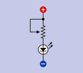
To use a potentiometer as a variable resistor or rheostat, one of its end terminals may be tied to the center terminal. If the unused end terminal is left unconnected, this raises the risk of picking up stray voltages or “noise” in sensitive circuits. In Figure 11-4, a potentiometer is shown adjust­ing a series resistance for an LED for demonstra­tion purposes. More typically, a trimmer would be used in this kind of application, since a user is unlikely to need to reset it.

Variants
Linear and Log Taper

If the resistive element in a potentiometer is of constant width and thickness, the electrical po­tential at the wiper will change in ratio with the rotation of the wiper and shaft (or with movement of a slider). This type of potentiometer is said to have a linear taper even though its ele­ment does not actually taper.

For audio applications, because human hearing responds nonlinearly to sound pressure, a po­tentiometer that has a linear taper may seem to have a very slow action at one end of its scale and an abrupt effect at the other. This problem used to be solved with a non-uniform or tapered re­


clip_image013Figure 11-3. Inside a potentiometer. See text for details .

sistive element. More recently, a combination of resistive elements has been used as a cheaper option. Such a potentiometer is said to have an audio taper or a log taper (since the resistance

clip_image011

Figure 11-4. A potentiometer can be used to adjust a series resistance, as shown in this schematic. Tying the wiper to one of the end terminals reduces the risk of picking up electrical noise.

may vary as a logarithm of the angle of rotation). A reverse audio taper or antilog taper varies in the opposite direction, but this type has become very uncommon.

Classic-style Potentiometer

This consists of a sealed circular can, usually be­ tween 0.5” and 1” in diameter, containing a re­sistive strip that is shaped as a segment of a circle. A typical example is shown in Figure 11-1, al­ though miniaturized versions have become more common. A shaft mounted on the can turns the internal wiper that presses against the strip. For panel-mount applications, a threaded bush­ ing at the base of the shaft is inserted through a hole in the front panel of the electronics enclo­sure, and a nut is tightened on the bushing to hold the potentiometer in place. Often there is also a small offset index pin that, when paired with a corresponding front panel hole, will keep the pot from spinning freely.

Many modern potentiometers are miniaturized, and may be packaged in a box-shaped plastic

enclosure rather than a circular can. Their power ratings are likely to be lower, but their principle of operation is unchanged. Two variants are shown in Figure 11-5.

clip_image016

Figure 11-5. Two modern miniaturized potentiometers. At left: 5K. At right: 10K. Both are rated to dissipate up to 50mW.

The three terminals on the outside of a potenti­ometer may be solder lugs, screw terminals, or pins for direct mounting on a circuit board. The pins may be straight or angled at 90 degrees.

The resistive element may use carbon film, plas­tic, cermet (a ceramic-metal mixture), or resistive wire wound around an insulator. Carbon-film po­ tentiometers are generally the cheapest, where­ as wire-wound potentiometers are generally the most expensive.

Wire-wound potentiometers may handle more power than the other variants, but as the wiper makes a transition from one turn of the internal wire element to the next, the output will tend to change in discrete steps instead of varying more smoothly.

In a potentiometer with detents, typically a spring-loaded lever in contact with notched in­ternal wheel causes the shaft to turn in discrete steps that create a stepped output even if the resistive element is continuous.

The shaft may be made of metal or plastic, with its length and width varying from one compo­nent to another. A control knob can be fitted to the end of the shaft. Some control knobs are push-on, others have a set screw to secure them. Shafts may be splined and split, or round and smooth, or round with a flat surface that matches the shape of a socket in a control knob and reuces the risk of a knob becoming loose and turning freely. Some shafts have a slotted tip to enable screwdriver adjustment.

Some shaft options for full-size potentiometers are shown in Figure 11-6.

clip_image018

Figure 11-6. Three shaft options for potentiometers.

Multiple-Turn Potentiometer

To achieve greater precision, a track inside a po­tentiometer may be manufactured in the form of a helix, allowing the wiper to make multiple turns on its journey from one end of the track to the other. Such multiple-turn potentiometers typi­cally allow 3, 5, or 10 turns to move the wiper from end to end. Other multiple-turn potentiometers may use a screw thread that advances a wiper along a linear or circular track. The latter is com­

parable with a trimmer where multiple turns of a screwdriver are used to rotate a worm gear that rotates a wiper between opposite ends of a cir­cular track.

Ganged Potentiometer

Two (or rarely, more) potentiometers can be stacked or combined so that their resistive ele­ments and wipers share the same shaft but can use different voltages or have different taper. Each resistance-wiper assembly is known as a cup, and the potentiometers are said to be ganged.

Flat ganged potentiometers combine two resis­tive elements in one enclosure. Some dual ganged potentiometers are concentric, meaning that the pots are controlled separately by two shafts, one inside the other. Suitable concentric knobs must be used. You are unlikely to find these potentiometers sold as components in limited quantities.

Switched Potentiometer

In this variant, when the shaft is turned clockwise from an initial position that is fully counter- clockwise, it flips an internal switch connected to external terminals. This can be used to power-up associated components (for example, an audio amplifier). Alternatively, a switch inside a poten­tiometer may be configured so that it is activated by pulling or pushing the shaft.

Slider Potentiometer

Also known as a slide potentiometer. This uses a straight resistive strip and a wiper that is moved to and fro linearly by a tab or lug fitted with a plastic knob or finger-grip. Sliders are still found on some audio equipment. The principle of op­eration, and the number of terminals, are identi­cal to the classic-style potentiometer. Sliders typ­ically have solder tabs or PC pins. In Figure 11-7, the large one is about 3.5” long, designed for mounting behind a panel that has a slot to allow the sliding lug to poke through. Threaded holes at either end will accept screws to fix the slider behind the panel. A removable plastic finger-grip

(sold separately, in a variety of styles) has been pushed into place. Solder tabs underneath the slider are hidden in this photo. The smaller slider is designed for through-hole mounting on a circuit board.

clip_image020

Figure 11-7. Slider potentiometers.

Trimmer Potentiometer

Often referred to as Trimpots, this is actually a proprietary brand name of Bourns. They are usu­ ally mounted directly on circuit boards to allow fine adjustment or trimming during manufacturing and testing to compensate for variations in other components. Trimmers may be single- turn or multi-turn, the latter containing a worm gear that engages with another gear to which the wiper is attached. Trimmers always have lin­ ear taper. They may be designed for screwdriver adjustment or may have a small knurled shaft, a thumb wheel, or a knob. They are not usually ac­cessible by the end user of the equipment, and their setting may be sealed or fixed when the equipment is assembled. In Figure 11-8, the beige Spectrol trimmer is a single-turn design, whereas the blue trimmer is multi-turn. A worm gear inside the package, beneath the screw head, engages with an interior gear wheel that rotates the wiper.

In Figure 11-9, a 2K trimmer potentiometer has a knurled dial attached to allow easy finger adjust­ment, although the dial also contains a slot for a flat-blade screwdriver.

clip_image022

Figure 11-8. Like most trimmers, these are designed for through-hole mounting on a circuit board.

clip_image024

Figure 11-9. A trimmer potentiometer with a knurled dial to facilitate finger adjustment.

How to Use it

Potentiometers are widely used in lamp dimmers and on cooking stoves (see Figure 11-10). In these applications, a solid-state switching device such as a triac (described in Volume 2) does the actual work of moderating the power to the lamp or the stove by interrupting it very rapidly. The potentiometer adjusts the duty cycle of the pow­er interruptions. This system wastes far less pow­ er than if the potentiometer controlled the light­ing or heating element directly as a rheostat. Since less power is involved, the potentiometer can be small and cheap, and will not generate significant heat.

clip_image026

Figure 11-10. Typical usage of a potentiometer in conjunction with a diac, triac, and capacitor to control the bright-

ness of an incandescent bulb, using an AC power supply.

Diacs and triacs are discussed in Volume 2.

The classic-style potentiometer was once used

universally to control volume, bass, and treble on audio equipment but has been replaced increas­ingly by digital input devices such as tactile switches (see “Tactile Switch” (page 34)) or ro­ tational encoders (see Chapter 8), which are more reliable and may be cheaper, especially when assembly costs are considered.

Because true logarithmic potentiometers have become decreasingly common, a linear potenti­ometer in conjunction with a fixed resistor can be used as a substitute, to control audio input. See Figure 11-11.

clip_image028

Figure 11-11. In this circuit, a 100K linear potentiometer is used in conjunction with a 22K resistor to create an approximately logarithmic volume control for an audio sys- tem with input coming from a mono jack socket at left.

A potentiometer may be used to match a sensor or analog input device to an analog-digital con­verter, or it can calibrate a device such as a tem­perature or motion sensor.

What Can Go Wrong
Wear and Tear

Since classic-style potentiometers are electro­ mechanical devices, their performance will de­teriorate as one part rubs against another. The long open slot of a slider potentiometer makes it especially vulnerable to contamination with dirt, water, or grease. Contact-cleaner solvent, lubricant-carrying sprays, or pressurized “duster” gas may be squirted into a potentiometer to try to extend its life. Carbon-film potentiometers are the least durable and in audio applications will eventually create a “scratchy” sound when they are turned, as the resistive element deteriorates.

If the wiper deteriorates to the point where it no longer makes electrical contact with the track, and if the potentiometer is being used as a vari­ able resistor, two failure modes are possible, shown in Figure 11-12. Clearly the right-hand schematic is a better outcome. This is an argu­ment for always tying the wiper to the “unused” end of the track.

If you are designing a circuit board that will go through a production process, temperature var­iations during wave soldering, and subsequent

clip_image030Figure 11-12. If the wiper of a potentiometer breaks (indicated by the loose arrow head) as a result of wear and tear, and the potentiometer is being used as a variable resistor, the voltage from it will drop to zero (top schematic) unless the wiper has been tied to one end of the track

(bottom schematic).

washing to remove flux residues, create hostile conditions for potentiometers, especially sliders where the internal parts are easily contaminated. It will be safer to hand-mount potentiometers after the automated process.

Knobs that Don’t Fit

Control knobs are almost always sold separately from potentiometers. Make sure the shaft of the potentiometer (which may be round, round- with-flat, or knurled) matches the knob of your choice. Note that some shaft diameters are ex­ pressed in inches, while others are metric.

Nuts that Get Lost

For panel-mounted potentiometers, a nut that fits the thread on the bushing is almost always included with the potentiometer; an additional nut and lock washer may also be supplied. Be­ cause there is no standardization of threads on potentiometers, if you lose a nut, you may have some difficulty finding an exact replacement.

A Shaft that Isn’t Long Enough

When choosing a shaft length, if in doubt, buy a potentiometer with a long shaft that you can cut to the desired length.

Sliders with No Finger Grip

Slider potentiometers are often sold without a knob or plastic finger-grip, which must be or­dered separately and may be available in differ­ent styles. The finger-grip usually push-fits onto the metal or plastic tab or lug that moves the slider to and fro.

Too Big to Fit

Check the manufacturer’s datasheet if you need to know the physical size of the potentiometer. Photographs may be misleading, as a traditional- style potentiometer that is 0.5” in diameter looks much the same as one that is 1” in diameter. High- wattage potentiometers will be more costly and physically large (2 to 3 inches in diameter). See Figure 11-13.

Overheating

Be sure to leave sufficient air space around a high-wattage potentiometer. Carefully calculate the maximum voltage drop and current that you may be using, and choose a component that is appropriately rated. Note that if you use the po­tentiometer as a rheostat, it will have to handle more current when its wiper moves to reduce its resistance. For example, if 12VDC are applied through a 10-ohm rheostat to a component that has a resistance of 20 ohms, current in the circuit will vary from 0.4 amps to 0.6 amps depending on the position of the rheostat. At its maximum setting, the rheostat will impose a 4V voltage drop and will therefore dissipate 1.6 watts from the full length of its resistive element. If the rheo­stat is reset to impose only a 4-ohm resistance, the voltage drop that it imposes will be 2V, the current in the circuit will be 0.5 amps, and the rheostat will therefore dissipate 1 watt from 4/10ths of the length of its resistive element. A

wire-wound potentiometer will be better able to handle high dissipation from a short segment of its element than other types of rheostat. Add a fixed resistor in series with a rheostat if necessary to impose a limit on the current.

clip_image032

Figure 11-13. The large potentiometer is approximately 3” in diameter, rated at 5 ohms, and able to handle more than 4 amps. The small potentiometer is 5/8” diameter, rated at 2K and 1/4 watt, with pins designed for through- hole insertion in a circuit board, and a grooved shaft that accepts a push-on knob. Despite the disparity in size, the principle of operation and the basic features are identical.

When using a trimmer potentiometer, limit the current through the wiper to 100mA as an abso­lute maximum value.

The Wrong Taper

When buying a potentiometer, remember to check the specification to find out whether it has linear or audio/log taper. If necessary, attach a meter, with the potentiometer set to its center position, to verify which kind of taper you have. While holding the meter probes in place, rotate the potentiometer shaft to determine which way an audio/log taper is oriented.


relay What It Does,How It Works ,Variants,Values,How to Use it and What Can Go Wrong

Properly known as an electromagnetic armature relay to distinguish it from a solid-state relay. However, the full term is very rarely used. It may also be described as an electro­ mechanical relay, but the term relay is normally understood to mean a device that is not solid state.

 
What It Does

A relay enables a signal or pulse of electricity to switch on (or switch off ) a separate flow of elec­tricity. Often, a relay uses a low voltage or low current to control a higher voltage and/or higher current. The low voltage/low current signal can be initiated by a relatively small, economical switch, and can be carried to the relay by rela­tively cheap, small-gauge wire, at which point the relay controls a larger current near to the load. In a car, for example, turning the ignition switch sends a signal to a relay positioned close to the starter motor.

While solid-state switching devices are faster and more reliable, relays retain some advantages. They can handle double-throw and/or multiple- pole switching and can be cheaper when high voltages or currents are involved. A comparison of their advantages relative to solid state re­ lays and transistors is tabulated in the entry on bipolar transistor in Figure 28-15.

Common schematic symbols for single-throw re­ lays are shown in Figure 9-1 and for double-

throw relays in Figure 9-2. The appearance and orientation of the coil and contacts in the sym­bols may vary significantly, but the functionality remains the same.

clip_image005

Figure 9-1. Commonly used schematic symbols for a SPST relay. The symbols are functionally identical.

clip_image007

Figure 9-2. Commonly used schematic symbols for a SPDT relay. The symbols are functionally identical.

How It Works

A relay contains a coil, an armature, and at least one pair of contacts. Current flows through the coil, which functions as an electromagnet and generates a magnetic field. This pulls the armature, which is often shaped as a pivoting bracket that closes (or opens) the contacts. These parts are visible in the simplified rendering of a DPST relay in Figure 9-3. For purposes of identification, the armature is colored green, while the coil is red and the contacts are orange. The two blue blocks are made of an insulating material, the one on the left supporting the contact strips, the one on the right pressing the contacts together when the armature pivots in response to a mag­netic field from the coil. Electrical connections to the contacts and the coil have been omitted for simplicity.

clip_image010

Figure 9-3. This simplified rendering shows the primary parts of a DPST relay. See text for details.

Various small relays, capable of handling a variety of voltages and currents, are pictured in Figure 9-4. At top-left is a 12VDC automotive re­ lay, which plugs into a suitable socket shown immediately below it. At top-right is a 24VDC SPDT

relay with exposed coil and contacts, making it suitable only for use in a very clean, dry environ­ment. Continuing downward, the four sealed re­ lays in colored plastic cases are designed to switch currents of 5A at 250VAC, 10A at 120VAC, 0.6A at 125VAC, and 2A at 30VDC, respectively. The two blue relays have 12VDC coils, while the red and yellow relays have 5V coils. All are nonlatching, except for the yellow relay, which is a latching type with two coils. At bottom-left is a 12VDC relay in a transparent case, rated to switch up to 5A at 240VAC or 30VDC.

clip_image012

Figure 9-4. An assortment of small DC-powered relays. See text for details.

The configuration of a relay is specified using the same abbreviations that apply to a switch. SP, DP, 3P, and 4P indicate 1, 2, 3, or 4 poles (relays with more than 4 poles are rare). ST and DT indicate single-throw or double-throw switching. These abbreviations are usually concatenated, as in 3PST or SPDT. In addition, the terminology Form

A (meaning normally open), Form B (normally closed), and Form C (double-throw) may be used, preceded by a number that indicates the number of poles. Thus “2 Form C” means a DPDT relay.

Variants
Latching

There are two basic types of relay: latching and nonlatching. A nonlatching relay, also known as a single side stable type, is the most common, and resembles a momentary switch or pushbutton in that its contacts spring back to their default state when power to the relay is interrupted. This can be important in an application where the re­ lay should return to a known state if power is lost. By contrast, a latching relay has no default state. Latching relays almost always have double- throw contacts, which remain in either position without drawing power. The relay only requires a short pulse to change its status. In semicon­ductor terms, its behavior is similar to that of a flip-flop.

In a single-coil latching relay, the polarity of volt­ age applied to the coil determines which pair of contacts will close. In a dual-coil latching relay, a second coil moves the armature between each of its two states.

Schematic symbols for a dual-coil latching relay are shown in Figure 9-5. Some symbol styles do not make it clear which switch position each coil induces. It may be necessary to read the manufacturer’s datasheet or test the relay by applying its rated voltage to randomly selected terminal pairs while testing for continuity between other terminal pairs.

Polarity

There are three types of DC relay. In a neutral re­ lay, polarity of DC current through the coil is ir­relevant. The relay functions equally well either way. A polarized relay contains a diode in series with the coil to block current in one direction. A biased relay contains a permanent magnet near the armature, which boosts performance when

clip_image016

Figure 9-5. Schematic symbols for a two-coil latching re- lay. The symbols are functionally identical.

current flows through the coil in one direction, but blocks a response when the current flows through the coil in the opposite direction. Man­ufacturers’ datasheets may not use this terminology, but will state whether the relay coil is sensitive to the polarity of a DC voltage.

All relays can switch AC current, but only an AC relay is designed to use AC as its coil current.

Pinout Variations

The layout and function of relay pins or quick connects is not standardized among manufac­turers. Often the component will have some in­dication of pin functions printed on it, but should always be checked against the manufacturer’s datasheet and/or tested for continuity with a meter.

Figure 9-6 shows four sample pin configurations, adapted from a manufacturer’s datasheet. These configurations are functionally quite different, although all of them happen to be for DPDT re­ lays. In each schematic, the coil of the relay is shown as a rectangle, while the pins are circles, black indicating an energized state and white in­ dicating a non-energized state. The bent lines show the possible connections between the poles and other contacts inside the relay. The contacts are shown as arrows. Thus, pole 4 can connect with either contact 3 or contact 5, while pole 9 can connect with either contact 8 or con­ tact 10.

Top-left: Polarized nonlatching relay in its resting condition, with no power applied. Top right: Single-coil latching relay showing energized contacts (black circles) when the coil is powered with the polarity indicated. If the polarity is re­ versed, the relay flips to its opposite state. Some manufacturers indicate the option to reverse po­ larity by placing a minus sign alongside a plus sign, and a plus sign alongside a minus sign. Bottom-left and bottom-right: Polarized latching relays with two coils, with different pinouts.

clip_image019

Figure 9-6. Relay pinouts depicted in the style commonly found in manufacturers’ datasheets, showing different re- lay types. Top-left: Single coil, non latching. Top-right: Sin- gle coil, latching. Bottom left: Two-coil, latching. Bottom right: Two-coil, latching, alternate pinouts. (Adapted from a Panasonic datasheet.)

In these diagrams, the relay is seen from above. Some datasheets show the relay seen from be­ low, and some show both views. Some manufac­turers use slightly different symbols to indicate interior functions and features. When in doubt, use a meter for verification.

Reed Relay

A reed relay is the smallest type of electrome­chanical relay with applications primarily in test equipment and telecommunications. With a coil resistance ranging from 500 to 2000 ohms, these relays consume very little power. The design con­

sists of a reed switch with a coil wrapped around it. Figure 9-7 shows a simplified rendering. The two black contacts are enclosed in a glass or plastic envelope and magnetized in such a way that a magnetic field from the surrounding coil bends them together, creating a connection. When power to the coil is disconnected, the magnetic field collapses and the contacts spring apart.

clip_image021

Figure 9-7. This simplified rendering shows a reed relay, consisting of a magnetized reed switch inside a glass or plastic pod, activated by a coil wrapped around it.

In Figure 9-8, two reed relays are shown, at top- left and center-right. At bottom-left, the type of relay on the right has been opened by a belt sander to reveal its copper coil and inside that, a capsule in which the relay contacts are visible.

Surface-mount reed relays can be smaller than 0.5” × 0.2”. Through-hole versions are often around 0.7” × 0.3” with pins in two rows, though some are available in SIP packages.

Reed relays have limited current switching ca­pacity and are not suitable to switch inductive loads.

Small Signal Relay

A small signal relay is also known as a low signal relay. This type may have a footprint as small as a reed relay but generally stands slightly taller, requires slightly more coil current, and is avail­ able in versions that can switch slightly higher

clip_image023

Figure 9-8. Three reed relays, one of which has had its packaging partially removed by a belt sander to reveal its copper coil and internal contacts.

voltages and currents. There are usually two rows of pins, spaced either 0.2” or 0.3” apart. The red and orange relays in Figure 9-4 are small signal relays.

Automotive Relays

An automotive relay is typically packaged in a cube-shaped black plastic case with quick- connect terminals at the bottom, typically plug­ged into a socket. Naturally they are designed to switch, and be switched by, a 12VDC supply.

General Purpose/Industrial

These relays cover a very wide range and are usually built without significant concern for size. They may be capable of switching high currents at high voltages. Typically they are designed to plug into a socket such as an octal base of the type that was once used for vacuum tubes. The base, in turn, terminates in solder tabs, screws, or quick connects and is designed to be screwed to a chassis. It allows the relay to be unplugged and swapped without resoldering.

Two industrial relays are shown in Figure 9-9. Both are DPDT type with 12VDC coils and rated to switch up to 10A at 240VAC. The one on the left has an octal base. An octal socket that fits an octal base is shown in Figure 9-10.

clip_image025

Figure 9-9. Two relays powered by 12VDC, capable of switching up to 10A at 240VAC.

clip_image027

Figure 9-10. An octal socket with screw terminals, de- signed to accept a relay with an octal base.

Time Delay Relay

Generally used to control industrial processes, a time delay relay switches an output on and off at

preset time intervals that can be programmed to repeat. The example in Figure 9-11 has a 12VDC coil and is rated to switch up at 10A at 240VAC. It has an octal base.

clip_image029

Figure 9-11. The control switches on a time-delay relay, allowing separately configured “on” and “off” intervals.

Contactor

A contactor functions just like a relay but is de­ signed to switch higher currents (up to thou­ sands of amperes) at higher voltages (up to many kilovolts). It may range from being palm-sized to measuring more than one foot in diameter, and may be used to control heavy loads such as very large motors, banks of high-wattage lights, and heavy-duty power supplies.

Values

Datasheets usually specify maximum voltage and current for the contacts, and nominal volt­ age and current for the coil, although in some cases the coil resistance is stated instead of nom­inal coil current. The approximate current con­sumption can be estimated, if necessary, by us­

ing Ohm’s Law. The minimum voltage that the relay needs for activation is sometimes described as the Must Operate By voltage, while the Must Release By voltage is the maximum coil voltage that the relay will ignore. Relays are rated on the assumption that the coil may remain energized for long periods, unless otherwise stated.

While the contact rating may suggest that a relay can switch a large load, this is  not necessarily true if the load has significant inductance.

Reed relays

Usually use a coil voltage of 5VDC and have a contact rating of up to 0.25A at 100V. Through-hole (PCB) versions may have a coil voltage of 5VDC, 6VDC, 12VDC, or 24VDC and in some cases claim to switch 0.5A to 1A at up to 100V, although this rating is strictly for a non inductive load.

Small signal/low signal relays

Usually use a coil voltage ranging from 5VDC to 24VDC, drawing about 20mA. Maximum switching current for non inductive loads ranges from 1A to 3A.

Industrial/general purpose relays

A very wide range of possible values, with coil voltages ranging up to 48VDC or 125VAC to 250VAC. Contact rating is typically 5A to 30A.

Automotive relays

Coil voltage of 12VDC, and contact rating often 5A at up to 24VDC.

Timer relays

Usually these specify a coil voltage of 12VDC, 24VDC, 24VAC, 125VAC, or 230VAC. The

timed interval can range from 0.1 sec to 9999 hours in some cases. Common values for contact ratings are 5A up to 20A, with a volt­ age of 125V to 250V, AC or DC.

How to Use it

Relays are found in home appliances such as dishwashers, washing machines, refrigerators, air conditioners, photocopy machines, and other products where a substantial load (such as a motor or compressor) has to be switched on and off by a control switch, a thermostat, or an electronic circuit.

Figure 9-12 shows a common small-scale appli­cation in which a signal from a microcontroller (a few mA at 5VDC) is applied to the base of a tran­sistor, which controls the relay. In this way, a logic output can switch 10A at 125VAC. Note the rec­tifier diode wired in parallel with the relay coil.

clip_image032

Figure 9-12. A signal from a digital source such as a microcontroller can switch substantial voltage and current if it is applied to the base of a transistor that activates a re- lay.

A latching relay is useful wherever a connection should persist when power is switched off or in­terrupted, or if power consumption must be minimized. Security devices are one common application. However, the circuit may require a “power reset” function to restore known default settings of latched relays.

A circuit including every possible protection against voltage spikes is shown in Figure 9-13, including a snubber to protect the relay contacts, a rectifier diode to suppress back-EMF generated by the relay coil, and another rectifier diode to

protect the relay from EMF generated by a motor when the relay switches it on and off. The snub ­ber can be omitted if the motor draws a relatively low current (below 5A) or if the relay is switching a noninductive load. The diode around the relay coil can be omitted if there are no semiconduc­ tors or other components in the circuit that are vulnerable to voltage spikes. However, a spike can affect components in adjacent circuits that appear to be electrically isolated. A severe spike can even be transmitted back into 125VAC house wiring. For information on using a resistor- capacitor combination to form a snubber, see “Snubber” (page 108).

clip_image034

Figure 9-13. This hypothetical schematic shows three types of protection against voltage spikes induced by an inductive load (a motor, in this instance) and the coil of the relay.

What Can Go Wrong
Wrong Pinouts

The lack of standardization of relay pinouts can cause errors if one relay is replaced with another that appears to be the same, but isn’t. In partic­ular, the pins that connect with normally closed contacts may trade places with pins connected with normally-open contacts, in relays from dif­ferent manufacturers.

Pinouts are also confusing in that some data­ sheets depict them from above, some from be­ low, and some from both perspectives.

Wrong Orientation

Small relays of through-hole type usually have pins spaced in multiples of 0.1”. This allows them to be inserted the wrong way around in a perfo­ rated board. Almost all relays have an identifica­tion mark molded into one end or one corner of the plastic shell. Manufacturers do not standard­ize the position and meaning of these marks, but they are usually replicated in datasheets. When using a relay of a type that you have not used before, it is a sensible precaution to test it with a meter to verify the functions of its terminals be­ fore installing it.

Wrong Type

A latching relay may have exactly the same ap­pearance as a non latching relay from the same manufacturer, and the same two pins may ener­gize the coil. However, in a latching relay, the contacts won’t spring back to their non- energized position, causing functional errors that may be difficult to diagnose. The part num­bers printed on latching and non latching ver­sions of the same relay may differ by only one letter or numeral and should be checked care­ fully.

Wrong Polarity

A relay with a DC-energized coil may require power to be applied with correct polarity and may malfunction otherwise.

AC and DC

A relay coil designed to be powered by DC will not work from AC and vice-versa. The contact rating of a relay is likely to be different depending whether it is switching AC or DC.

Chatter

This is the noise created by relay contacts when they make rapid intermittent connection. Chat­ter is potentially damaging to relay contacts and should be avoided. It can also create electrical noise that interferes with other components. Likely correctible causes of chatter include insuf­ficient voltage or power fluctuations.

Relay Coil Voltage Spike

A relay coil is an inductive device. Merely switch­ing a large relay on and off can create voltage spikes. To address this problem, a rectifier diode should be placed across the coil terminals with polarity opposing the energizing voltage.

Arcing

This problem is discussed in the switch entry of this encyclopedia. See “Arcing” (page 47). Note that because the contacts inside a reed relay are so tiny, they are especially susceptible to arcing and may actually melt and weld themselves to­ get her if they are used to control excessive cur­ rent or an inductive load.

Magnetic Fields

Relays generate magnetic fields during opera­tion and should not be placed near components that are susceptible.

The reed switch inside a reed relay can be unex­pectedly activated by an external magnetic field. This type of relay may be enclosed in a metal shell to provide some protection. The adequacy of this protection should be verified by testing the relay under real-world conditions.

Environmental Hazards

Dirt, oxidation, or moisture on relay contacts is a significant problem. Most relays are sealed and should remain sealed.

Relays are susceptible to vibration, which can af­fect the contacts and can accelerate wear on

moving parts. Severe vibration can even damage a relay permanently. Solid-state relays (dis­ cussed in Volume 2) should be used in harsh en­vironments.


switch What It Does,How It Works ,Variants,Values,How to Use it and What Can Go Wrong


The term switch refers here to a physically operated mechanical switch, controlled by flipping a lever or sliding a knob. Although there is some overlap of function, rotary switches and pushbuttons have their own separate entries. Solid-state switching com­ponents are described in entries for bipolar transistor, unijunction transistor, and field-effect transistor. Integrated-circuit switching devices will be found in Volume 2. Coaxial switches are used for high-frequency signals, and are not included in this ency­clopedia. Multidirectional switches differentiate up, down, left, right, diagonal, rotational, and other finger inputs, and are not included in this encyclopedia.

What It Does

A switch contains at least two contacts, which close or open when an external lever or knob is flipped or moved. Schematic symbols for the most basic type of on-off switch are shown in Figure 6-1.

The most fundamental type of switch is a knife switch, illustrated in Figure 6-2. Although it was common in the earliest days of electrical discov­ery, today it is restricted to educational purposes in schools, and (in a more robust format) to AC electrical supply panels, where the large contact area makes it appropriate for conducting high amperages, and it can be used for “hot switching” a substantial load.

How It Works

The pole of a switch is generally connected with a movable contact that makes or breaks a con­nection with a secondary contact. If there is only one pole, this is a single-pole switch. If there is an additional pole, electrically isolated from the

clip_image004

Figure 6-1. The two most common schematic symbols for a SPST switch, also known as an on-off switch. The symbols are functionally identical.

first, with its own contact or set of contacts, this is a two-pole switch, also known as a double- pole switch. Switches with more than 4 poles are uncommon.

If there is only one secondary contact per pole, this is a single-throw or ST switch, which may also be described as an on-off or off-on switch. If there is an additional secondary contact per pole, and the pole of the switch connects with the second contact while disconnecting from the first, this is a double-throw or DT switch, also known as a two– way switch.

clip_image007

Figure 6-2. A DPST knife switch intended for the educational environment.

A double-throw switch may have an additional center position. This position may have no con­nection (it is an “off” position) or in some cases it connects with a third contact.

Where a switch is spring-loaded to return to one of its positions when manual pressure is released, it functions like a pushbutton even though its physical appearance may be indistinguishable from a switch.

Variants

Float switch, mercury switch, reed switch, pressure switch, and Hall-effect switch are considered as sensing devices, and will be found in Volume 3.

Terminology

Many different types of switches contain parts that serve the same common functions. The ac­tuator is the lever, knob, or toggle that the user turns or pushes. A bushing surrounds the actua­ tor on a toggle-type switch. The common con­ tact inside a switch is connected with the pole of

the switch. Usually a movable contact is attached to it internally, to touch the secondary contact, also known as a stationary contact when the movable contact is flipped to and fro.

Poles and Throws

Abbreviations identify the number of poles and contacts inside a switch. A few examples will make this clear:

SPST also known as 1P1T

Single pole, single throw

DPST also known as 2P1T

Double pole, single throw

SPDT also known as 1P2T

Single pole, double throw

3PST also known as 3P1T

Three pole, single throw

Other combinations are possible.

In Figure 6-3, schematic symbols are shown for double-throw switches with 1, 2, and 3 poles. The dashed lines indicate a mechanical connection, so that all sections of the switch move together when the switch is turned. No electrical connec­tion exists between the poles.

clip_image010

Figure 6-3. Schematic symbols to represent three types of double-throw switch. Top left: Single-pole. Bottom left: Double-pole. Right: Triple-pole, more commonly known as 3-pole.

On-Off Behavior

The words ON and OFF are used to indicate the possible states of a switch. The additional word NONE is used by some manufacturers to indicate that a switch does not have a center position. Some manufacturers don’t bother with the word NONE, assuming that if the word is omitted, a center position does not exist.

ON-OFF or ON-NONE-OFF

A basic on-off SPST switch with no center position.

ON-ON or ON-NONE-ON

A basic SPDT switch with no center position.

ON-OFF-ON

A double-throw switch with center-off posi­tion (no connection when the switch is cen­tered).

ON-ON-ON

A triple-throw switch where the center po­sition connects with its own set of terminals.

Parentheses are used in descriptions of spring- loaded switches to indicate a momentary state that lasts only as long as pressure is applied to the actuator.

(ON)-OFF or OFF-(ON)

A spring-loaded switch that is normally off and returns to that position when pressure is released. Also known as NO (normally open), and sometimes described as FORM A. Its performance is similar to that of a push­ button and is sometimes described as a make-to-make connection.

ON-(OFF) or (OFF)-ON

A spring-loaded switch that is normally on and returns to that position when pressure is released. This is sometimes described as a make-to-break connection. Also known as NC (normally closed), and sometimes de­ scribed as FORM B.

(ON)-OFF-(ON)

A spring-loaded double-throw switch with a no-connection center position to which it returns when pressure on its actuator is re­ leased.

Other combinations of these terms are possible. Most double-throw switches break the connec­tion with one contact (or set of contacts) before making the connection with the second contact (or set of contacts). This is known as a break before make switch. Much less common is a make before break switch, also known as a shorting switch, which establishes the second connection a mo­ment before the first connection is broken. Use of a shorting switch may cause unforeseen con­ sequences in electronic components attached to it, as both sides of the switch will be briefly con­nected when the switch is turned.

Snap-Action

Also known as a limit switch and sometimes as a micros witch or basic switch. This utilitarian design is often intended to be triggered mechanically rather than with finger pressure, for example in 3D printers. It is generally cheap but reliable.

Two snap-action switches are shown in Figure 6-4. A sectional view of a snap-action ON- (ON) limit switch is shown in Figure 6-5. The pole contacts are mounted on a flexible strip which can move up and down in the center of the switch. The strip has a cutout which allows an inverted U-shaped spring to flip to and fro. It keeps the contacts pressed together in either of the switch states.


clip_image014

Figure 6-4. Two SPDT snap-action switches, also known as limit switches. The one on the right is full-size. The one on the left is miniature, with an actuator arm to provide additional leverage. The arm may be trimmed to the required length.

clip_image016

Figure 6-5. Top: Two contacts inside this limit switch are touching by default. Bottom: When the external button is pressed, it pushes a flexible metal strip downward until it connects with the lower contact. The inverted-U–shaped component is a spring that rests inside a cutout in the flexible strip and resists motion through the central part of its travel.

The term snap action refers to a spring-loaded internal mechanism which snaps to and fro be­ tween its two positions. This type of switch is usually SPDT and has a momentary action; in other words, it functions in ON-(ON) mode, al­ though OFF-(ON) and (less often) ON-(OFF) ver­sions are available. The body of the switch is sealed, with a small button protruding through a hole. A thin metal arm may provide additional leverage to press the button. A roller may be mounted at the end of the arm so that the switch can be activated as it slides against a moving mechanical component such as a cam or a wheel. The switch is commonly used to limit the travel or rotation of such a component. Literally thou­ sands of variants are available, in different sizes, requiring different amounts of force for activa­tion. Subminiature snap-action switches can often be actuated by a pressure of only a few grams.

Rocker

Three rocker switches are shown in Figure 6-6. A sectional view of a rocker switch is shown in Figure 6-7. In this design, a spring-loaded ball bearing rolls to either end of a central rocker arm when the switch is turned. Rocker switches are often used as power on-off switches.

Slider

Many types of slider switch (also known as slide switch) are widely used as a low-cost but versatile way to control small electronic devices, from clock-radios to stereos. The switch is usually mounted on a circuit board, and its knob or cap protrudes through a slot in the panel. This design is more vulnerable to dirt and moisture than oth­er types of switch. It is usually cheaper than a toggle switch but is seldom designed for use with a high current.

Most slide switches have two positions, and func­tion as SPDT or DPDT switches, but other config­urations are less commonly available with more poles and/or positions. A subminiature slide switch is shown in Figure 6-8, while some sche­matic representations are shown in Figure 6-9,

clip_image018

Figure 6-6. Three rocker switches, the upper two de- signed for push-insertion into a suitably sized rectangular hole in a panel. The switch at front-center is intended to be screwed in place, and is more than 20 years old, show- ing that while the choice of materials has changed, the ba- sic design has not.

clip_image020

Figure 6-7. This sectional view of a rocker switch shows a spring-loaded ball-bearing that rolls to and fro along a rocker arm, connecting either pair of contacts when the switch is turned.

where a black rectangle indicates a sliding inter­nal contact, and a terminal that functions as a pole is identified with letter P in each case. Top left: A SPDT switch using a two-position slider. Top right: A 4PDT slide switch. Bottom left: There are no poles in this switch, as such. The slider can

short together any of four pairs of contacts. Bot­ tom right: The slider shorts together three pos­sible pairs of contacts out of four. Here again, there is no pole.

Note that the schematic representation of a slide switch may be identical to that of a slide push­ button. A schematic should be inspected care­ fully to determine which type is intended.

clip_image022

Figure 6-8. This subminiature slide switch is less than half an inch long, rated 0.3A at 30VDC. Larger versions look almost identical, but can handle only slightly more current.

The representation of sliders in schematics has not been standardized, but the samples shown are common.

Toggle

A toggle switch provides a firm and precise action via a lever (the toggle) that is usually tear-drop shaped and nickel plated, although plastic tog­gles are common in cheaper variants. Formerly used to control almost all electronic components (including early computers), the toggle has de­clined in popularity but is still used in applica­tions such as automobile accessory kits, motor- boat instrument panels, and industrial controls.

Three miniature DPDT toggle switches are shown in Figure 6-10. Two full-size, heavy-duty toggle switches are shown in Figure 6-11. A full-size, four-pole, double-throw heavy-duty toggle switch is shown in Figure 6-12. Toggle switches with more poles are extremely rare.


clip_image024

Figure 6-9. Slide switch schematics. Each black rectangle represents a movable contact that connects two pairs of fixed contacts at a time. Detailed commentary on these variants will be found in the body of the text. Manufacturers may use variants of these symbols in their datasheets (for example, the gray rectangle indicating an insulating contact carrier, at top right, may be represented as a single line, or a black outline with a white center).

clip_image026

Figure 6-10. Three miniature toggle switches with current ratings ranging from 0.3A to 6A at 125VAC. Each small square in the background grid measures 0.1” x 0.1”.

An automotive toggle switch is shown in Figure 6-13. Its plastic toggle is extended to min­imize operating error.

clip_image028

Figure 6-11. Two full-size toggle switches capable of handling significant current. At left, the switch terminates in quick-connect terminals. At right, the switch has solder terminals (some of them containing residual traces of sol- der).

clip_image030

Figure 6-12. A 4PDT full-size toggle switch with solder terminals, capable of switching 25A at 125VAC. Four-pole switches are relatively unusual.

clip_image032

Figure 6-13. A toggle switch intended for control of auto- motive accessories.

High-end toggle switches are extremely durable and can be sealed from environmental

contamination with a thin boot made from mol­ded rubber or vinyl, which screws in place over the toggle, using the thread on the switch bush­ing. See Figure 6-14.

clip_image034

Figure 6-14. A rubber or vinyl boot can be used to protect a toggle switch from contamination with dirt or water. Each boot contains a nut that screws onto the threads of a toggle switch, as shown at left.

A locking toggle switch has a toggle that must be pulled out against the force of a retaining spring, before the toggle can be moved from one posi­tion to another. The toggle then snaps back into place, usually engaging in a small slot in the bushing of the switch.

DIP

A DIP switch is an array of very small, separate switches, designed for mounting directly on a circuit board, either in through-hole or surface- mount format. Through-hole DIP switches have two rows of pins with a 0.1” pitch, the rows being spaced 0.3” apart to fit a standard DIP (dual-inline package) socket or comparable configuration of holes in the board. Surface-mount DIP switches may have 0.1” or 0.05” pitch.

Most DIP arrays consist of SPST switches, each of which can close or open a connection between two pins on opposite sides of the switch body. The switch positions are usually labelled ON and OFF. Figure 6-15 shows a selection of DIP switches. Figure 6-16 shows the internal connec­tions in a DIP switch.

clip_image036

Figure 6-15. As shown here, DIP switches are available with a variety of “positions,” meaning the number of switches, not the number of switch states.

clip_image038

Figure 6-16. The interior connections of a 16-pin DIP switch.

The number of switches in a DIP array is usually referred to as its number of “positions.” This should not be confused with the two positions of each physical switch lever. SPST DIP switches are made with 1, 2, 3, 4, 5, 6, 7, 8, 9, 10, 12, and 16 positions.

Early IBM-compatible desktop computers often required the user to set the position of an internal DIP switch when making routine upgrades such as installing an additional disk drive. While this feature is now obsolete, DIP switches are still used in scientific equipment where the user is expected to be sufficiently competent to open a cabinet and poke around inside it. Because of the 0.1” spacing, a small screwdriver or the tip of a pen is more appropriate than a finger to flip in­dividual levers to and fro.

DIP switches may also be used during prototype development, as they allow a convenient way to test a circuit in numerous different modes of op­eration.

Most DIP switches have wire terminals which are just long enough for insertion into a standard breaboard.

DIP switch package options include standard, low-profile, right-angle (standing at 90 degrees relative to the circuit board), and piano (with switch levers designed to be pressed, like tiny rocker switches, instead of being flipped to and fro).

Some SPDT, DPST, DPDT, 3PST, and 4PST variants exist, but are uncommon. Multiple external pins connect with the additional internal switch con­tacts, and a manufacturer’s datasheet should be consulted to confirm the pattern of internal con­nections. A surface-mount, 0.1” pitch, DPST DIP switch is shown in Figure 6-17, with a plastic cov­er to protect the switches from contamination during wave soldering (at left), and with the cov­er peeled off (at right).

clip_image040

Figure 6-17. A SPDT surface-mount double-throw DIP switch, sold with a plastic cover (shown at left) to protect it during wave soldering. The cover has been removed at right.

SIP

A SIP switch is an array of small, separate switches, identical in concept to a DIP switch, but using only one row of pins instead of a double row. The applications for SIP switches are the

same as DIP switches; the primary difference is simply that the SIP switch occupies a little less space, while being perhaps slightly less conve­nient to use.

One terminal of each switch usually shares a common bus. The internal connections in a typ­ical 8-pin SIP array are shown in Figure 6-18. Pin spacing is 0.1”, as in a typical DIP switch.

clip_image042

Figure 6-18. The interior connections of an 8-pin SIP switch incorporating a common bus.

Paddle

A paddle switch has a flat-sided tab-shaped plas­tic actuator, relatively large to allow a firm, error- free grip. Internally it is often comparable with a rocker switch, and is generally used with AC pow­er. Some toggle-switch bodies are also sold with paddle-shaped actuators. A subminiature pad­dle switch is shown in Figure 6-19.

clip_image044

Figure 6-19. A subminiature paddle switch. Full-size versions are often used as power switches.

Vandal Resistant Switch

Typically fabricated from stainless steel, this is designed to withstand most types of abuse and is also weather-proof. The pushbuttons that al­ low pedestrians to trigger a traffic signal are a form of vandal-resistant switch.

Tactile Switch

This is considered to be a pushbutton, and is described in that entry. See “Tactile Switch” (page 34).

Mounting Options

A panel mount switch generally has a threaded bushing that is inserted from behind the front panel of a product, through a hole of appropriate size. It is supplied with a lock washer and a nut (often, two nuts) that fit the thread on the switch bushing.

Front panel mount usually means that screws visi­ble from the front of the panel are attached to a bracket on the switch behind the panel. The ac­tuator of the switch is accessible through a cut­ out in the panel. This mounting style is mostly used for rocker switches and sometimes for slide switches.

Subpanel mount means that the switch is attach­ ed to a separate plate or chassis behind the con­trol panel. The actuator of the switch is accessible through a cutout.

Snap-in mount requires a switch with flexible plastic or metal tabs each side, designed to push through a cutout in the panel, at which point the tabs spring out and retain the switch.

PC mount switches have pins that are soldered into a printed circuit board. They may have ad­ditional solderable lugs to provide mechanical support.

Surface mount switches are attached to a board in the same manner as other surface-mount components.


Termination

Switches (and pushbuttons) are available with a variety of terminals.

Solder lugs are small tabs, each usually perforated with a hole through which the end of a wire can be inserted prior to soldering.

PC terminals are pins that protrude from the bot­ tom of the switch, suitable for insertion in a print­ ed circuit board. This style is also known as a through-hole. The terminals may have a right- angle bend to allow the component to be moun­ ted flat against the board, with the switch actua­ tor sticking out at the side. This termination style is known as right-angle PC. Many manufacturers offer a choice of straight or bent pin terminals, but the component may be listed in a catalog under either of those options, with no indication that other options exist. Check manufacturer da­ tasheets carefully.

Quick connect terminals are spade-shaped to ac­cept push-on connectors, commonly used in au­ tomotive applications. Hybrid quick-connect ter­minals that can also function as solder lugs are sometimes offered as an option.

Screw terminals have screws premounted in flat terminals, for solderless attachment of wires.

Wire leads are flexible insulated wires, often with stripped and tinned ends, protruding at least an inch from the body of the component. This op­tion is becoming uncommon.

Contact Plating Options

The internal electrical contacts of a switch are usually plated with silver or gold. Nickel, tin, and silver alloys are cheaper but less common. Other types are relatively rare.

alues

Switches designed for electronic devices vary widely in power capability, depending on their purpose. Rocker switches, paddle switches, and toggle switches are often used to turn power on and off, and are typically rated for 10A at 125VAC,

although some toggle switches go as high as 30A. Snap-action or limit switches may be simi­larly rated, although miniature versions will have reduced capability. Slide switches cannot handle significant power, and are often rated around 0.5A (or less) at 30VDC. DIP and SIP switches have a typical maximum rating of 100mA at 50V and are not designed for frequent use. Generally they are used only when the power to the device is off.

How to Use it
Power Switches

When a simple SPST switch is used to turn DC power on and off, it conventionally switches the positive side of the power supply, also some­ times known as the high side. The primary reason for following this convention is that it is widely used; thus, following it will reduce confusion.

More importantly, an on-off switch that controls AC power must be used on the “live” side of the supply, not the “neutral” side. If you have any doubts about these concepts (which go beyond the scope of this book), consult a reference guide on this subject. Using a DPST component to switch both sides of an AC supply may be a worthwhile additional precaution in some applications. The ground wire of an AC supply should never be switched, because the device should always be grounded when it is plugged into an electric outlet.

Limit Switches

An application for two limit switches with a DC motor and two rectifier diodes is shown in Figure 6-20. This diagram assumes that the mo­ tor turns clockwise when its lower terminal is positive, and counter-clockwise when its upper terminal is positive. Only two terminals are used (and shown) in each limit switch; they are chosen to be normally-closed. Other terminals inside a switch may exist, may be normally-open, and can be ignored.

The motor is driven through a dual-coil, DPDT latching relay, which will remain in either posi­

clip_image047

Figure 6-20. In this schematic, normally-closed limit switches are opened by pressure from an arm attached to a motor, thus switching off its power at each end of its permitted travel and preventing overload and burnout. A two-coil latching relay activates the motor. Rectifier di- odes allow power to reach the motor to reverse its rota- tion when a limit switch is open.

tion indefinitely without drawing power. When the upper coil of the relay receives a pulse from a pushbutton or some other source, the relay flips to its upper position, which conducts posi­ tive current through the lower limit switch, to the lower terminal of the motor. The motor turns clockwise until the arm attached to its shaft hits the lower limit switch and opens it. Positive cur­ rent is blocked by the lower diode, so the motor stops.

When the lower coil of the relay is activated, the relay flips to its lower position. Positive current can now reach the upper side of the motor through the upper limit switch. The motor runs counter-clockwise until its arm opens the upper limit switch, at which point the motor stops again. This simple system allows a DC motor to be run in either direction by a button-press of any duration, without risk of burnout when the mo­ tor reaches the end of its travel. It has been used for applications such as raising and lowering powered windows in an automobile.


A DPDT pushbutton could be substituted for the latching relay if manual control, only, is accepta­ble. However, in this scenario, sustained pressure on the pushbutton would be necessary to move the motor arm all the way to the opposite end of its travel. A DPDT switch might be more appro­priate than a pushbutton.

Logic Circuits

Logic circuits that depend purely on switches can be constructed (for example, to add binary num­bers) but are rare and have no practical applica­tions. The most familiar and simplest example of manually switched logic is a pair of SPDT switches in house wiring, one positioned at the top of a flight of stairs and the other at the bot­ tom, as shown in Figure 6-21. Either switch will turn the light on if it is currently off, or off if it is currently on. To extend this circuit by incorpo­rating a third switch that has the same function as the other two, a DPDT switch must be inserted. See Figure 6-22.

clip_image049

Figure 6-21. SPDT switches are commonly used in house wiring so that either of them will turn a shared light on if it is off, or off it is on.

clip_image051

Figure 6-22. A DPDT switch must be inserted if three switches must have identical function to control the on-off state of a single light bulb.


Alternatives

As microcontrollers have become cheaper and more ubiquitous, they have taken over many functions in electronic products that used to be served by switches. A menuing system driven by a microcontroller can use one rotational en­ coder with a SPST pushbutton built into it to se­lect and adjust numerous parameters in a device such as a car stereo, where functions were once selected and adjusted by individual switches and potentiometers. The rotational-encoder option takes up less space, is cheaper to build (assuming a microcontroller is going to be used in the de­ vice for other purposes anyway), and can be more reliable, as it reduces the number of elec­tromechanical parts. Whether it is easier to use is a matter of taste. Cost and ergonomics may be the primary factors to consider when choosing where and how to use switches.

What Can Go Wrong
Arcing

The contacts inside a switch will be rapidly ero­ded if arcing (pronounced “arking”) occurs. An electric arc is a spark that tends to form when a switch is opened while conducting a high cur­ rent or high voltage (typically 10A or more and 100V or more). The most common cause is an inductive load that generates back-EMF when it is switched on and forward-EMF when it is switched off. The surge can be many times the amperage that the load draws during continu­ous operation. In DC circuits, arcing can be re­duced by using a rectifier diode in parallel with the load (with its polarity blocking normal cur­ rent flow). This is often referred to as a flyback diode or freewheeling diode. In AC circuits, where a diode cannot be used in this way, a snubber (a simple combination of capacitor and resistor) may be placed around the load. A snubber can also be used around the switch itself, in DC cir­cuits. See “Snubber” (page 108).

When switching an inductive load, it is generally prudent to use switches rated for twice as much current as the circuit will normally draw.

Dry Joints

Switches that control significant current will have substantial terminals, and these terminals will be attached to heavy-gauge wire. When using sol­ der to make this type of connection, the combined heat capacity of the wire and the terminal will sink a lot more heat than a small component on a circuit board. At least a 30W soldering iron should be used. Lower-wattage irons may be in­ capable of melting the solder completely (even though they seem to), and a “dry joint” will result, which can have a relatively high electrical resist­ance and will be mechanically weak, liable to break later. Any good solder joint should with­ stand flexing of the wire attached to it.

Short Circuits

Because many switches are still wired in with sol­ der tabs, screw terminals, or quick-connect ter­minals, wires that become accidentally detached can be a significant hazard. Heat-shrink tubing should be applied to enclose wires and terminals at the rear of a power switch, as an additional precaution. Power switches should always be used in conjunction with appropriate fuses.

Contact Contamination

Sealed switches should be used in any environ­ment where dirt or water may be present. Slide switches are especially vulnerable to contamina­tion, and are difficult to seal. Switches used in audio components will create “scratchy” sounds if their contacts deteriorate.

Wrong Terminal Type

Because switches are available with a wide vari­ety of terminal types, it’s easy to order the wrong type. Switches may be supplied with pins for through-hole insertion in circuit boards; screw terminals; quick-disconnect terminals; or solder lugs. Variants may also be available for surface

mount. If a project requires, for example, the in­ sertion of pins in a printed circuit board, and a switch is supplied with solder lugs, it will be un­ usable.

Part numbers generally include codes to identify each terminal variant, and should be studied carefully.

Contact Bounce

Also known as switch bounce. When two contacts snap together, extremely rapid, microscopic vi­brations occur that cause brief interruptions be­ fore the contacts settle. While this phenomenon is not perceptible to human senses, it can be per­ ceived as a series of multiple pulses by a logic chip. For this reason, various strategies are used to debounce a switch that drives a logic input. This issue is explored in detail in the entry on logic chips in Volume 2 of the encyclopedia.

Mechanical Wear

Any toggle or rocker switch contains a mechan­ical pivot, which tend to deteriorate in harsh en­vironments. Friction is also an issue inside these switches, as the design often entails the rounded tip of a lever rubbing to and fro across the center of a movable contact.

The spring inside a snap switch or limit switch may fail as a result of metal fatigue, although this is rare. A slide switch is far less durable, as its con­tacts rub across each other every time the switch changes position.

In any application that entails frequent switch­ing, or where switch failure is a critical issue, the most sensible practice is to avoid using cheap switches.

Mounting Problems

In a panel-mount switch that is secured by turn­ ing a nut, the nut may loosen with use, allowing the component to fall inside its enclosure. Con­ versely, overtightening the nut may strip the threads on the switch body, especially in cheaper components where the threads are molded into

plastic. Consider applying a drop of Loc-Tite or similar adhesive after moderately tightening the nut. Note that nut sizes vary widely, and finding a replacement may be time-consuming.

Cryptic Schematics

In some circuit schematics, the poles of a multi- pole switch may be visually separated from each

other, even at opposite sides of the page, for convenience in drawing the schematic. Dotted lines usually, but not always, link the poles. In the absence of dotted lines, switch segments are often coded to indicate their commonality. For example, SW1(a) and SW1(b) are almost certainly different parts of the same switch, with linked poles.


rotary switch What It Does,How It Works ,Variants,Values,How to Use it and What Can Go Wrong

Not to be confused with rotational encoder, which has its own entry in this encyclopedia.

What It Does

A rotary switch makes an electrical connection between a rotor, mounted on a shaft that is turned by a knob, and one of two or more sta­tionary contacts. Traditionally, it was the compo­nent of choice to select wavebands on a radio receiver, broadcast channels on a television or inputs on a stereo preamplifier. Since the 1990s, it has been substantially superceded by the ro­tational encoder. However it still has applica­tions in military equipment, field equipment, industrial control systems, and other applica­tions requiring a rugged component that will withstand heavy use and a possibly harsh envi­ronment. Also, while the output from a rotational encoder must be decoded and interpreted by a device such as a microcontroller, a rotary switch is an entirely passive component that does not require any additional electronics for its func­tionality.

Two typical schematic symbols for a rotary switch are shown in Figure 7-1. They are functionally identical. A simplified rendering of the interior of a traditional-style rotary switch is shown in Figure 7-2. A separate contact (not shown) con­nects with the rotor, which connects with each

of the stationary contacts in turn. The colors were chosen to differentiate the parts more clearly, and do not correspond with colors in an actual switch.

clip_image005

Figure 7-1. Typical schematic symbols for a rotary switch. The two symbols are functionally identical. The number of contacts will vary depending on the switch.

A selection of rotary switches is shown in Figure 7-3. At top-left is an open frame switch, providing no protection to its contacts from con­taminants. This type of component is now rare. At top-right is a twelve-position, single-pole switch rated 2.5A at 125VAC. At front-left is a four- position, single-pole switch rated 0.3A at 16VDC or 100VAC. At front right is a two-position, two- pole switch with the same rating as the one be­ side it. All the sealed switches allow a choice of panel mounting or through-hole printed circuit board mounting.

clip_image007

Figure 7-2. A simplified rendering of interior parts in a ba- sic SP6T rotary switch. Arbitrary colors have been added for clarity.

How It Works

A switch may have multiple poles, each connect­ ing with its own rotor. The rotors are likely to be on separate decks of the switch, but two, three, or four rotors, pointing in different directions, may be combined on a single deck if the switch has only a small number of positions.

Rotary switches are usually made with a maxi­ mum of twelve positions, but include provision for limiting the number of positions with a stop. This is typically a pin, which may be attached to a washer that fits around the bushing of the switch. The pin is inserted into a choice of holes to prevent the switch from turning past that point. For example, an eight-position rotary switch can be configured so that it has only seven (or as few as two) available positions.

A specification for a rotary switch usually in­cludes the angle through which the switch turns between one position and the next. A twelve- position switch usually has a 30-degree turn an­ gle.

clip_image009

Figure 7-3. A selection of rotary switches. See text for de- tails.

Variants
Conventional

The traditional style of rotary switch is designed to be panel-mounted, with a body that ranges from 1” to 1.5” in diameter. If there is more than one deck, they are spaced from each other by about 0.5”. The switch makes an audible and tac­tile “click” as it is turned from one position to the next.

A rugged sealed five-deck rotary switch is shown in Figure 7-4. It has five poles (one per deck), and a maximum of 12 positions. The contacts are rat­ed 0.5A at 28VDC. This type of heavy-duty com­ ponent is becoming relatively rare.

If the rotor in a switch establishes a connection with the next contact a moment before breaking the connection with the previous contact, this is known as a shorting switch, which may also be described as a make-before-break switch. In a non shorting or break-before-make switch, a tiny

clip_image014

Figure 7-4. A five-pole, twelve-position rotary switch.

interval separates one connection from the next. This can be of significant importance, depending on the components that are connected with the switch.

The shaft may be round, splined, or D-shaped in section. A knob is seldom supplied with a switch and must be chosen to match the shaft. Some shaft dimensions are metric, while others are measured in inches, with 1/4” diameter being the oldest standard. Some switches with a splined shaft are supplied with an adapter for a knob of D-shaped internal section; the adapter can be slipped onto the shaft in any of 12 or more posi­tions, to minimize the inconvenience of position­ing the body of the switch itself so that the knob is correctly oriented in relation to positions print­ ed on the face of the panel.

Miniature rotary switches may be as small as 0.5” diameter, and usually terminate in pins for through-hole mounting on a PC board. Miniature switches usually have lower current ratings than full-size switches.

Rotary switches must be securely anchored to resist the high turning forces that can be inflicted

upon them by users. In a panel-mount design, a nut is tightened around a thread on the bushing of the switch. Through-hole versions can be se­ cured to the PC board with the shaft protruding loosely through a cutout in the panel. To mini­mize mechanical stress on the circuit board, the detents in a PC-board switch are usually weaker than in a full-size switch, and the knob is usually smaller, allowing less leverage.

Rotary DIP

A conventional DIP switch is a linear array of min­iature SPST switches designed to fit a standard DIP (dual-inline package) layout of holes in a cir­cuit board. It is described in the switch entry of this encyclopedia. A rotary DIP switch (also known as an encoded output rotary switch or a coded rotary switch) does not conform with a DIP layout, despite its name. It is approximately 0.4” square and usually has five pins, one of which can be considered the input or common pin while the other four can function as outputs. The pins are spaced at 0.1” pitch from one another. Pin function and layout are not standardized.

A dial on top of the switch has either 10 positions (numbered 0 through 9) or 16 positions (0 through 9 followed by letters A through F). One switch of each type is shown in Figure 7-5.

Each position of the dial closes pairs of contacts inside the component to create a unique binary- coded decimal pattern (in a 10-position switch) or binary-coded hexadecimal pattern (in the 16- position switch) on the four output pins. The pin states are shown in Figure 7-6. A rotary DIP switch is a relatively flimsy device, and is not designed for frequent or heavy use. It is more likely to be a “set it and forget it” device whose state is estab­lished when it is installed in a circuit board.

Because each position of the switch is identified with a unique binary pattern, this is an example of absolute encoding. By contrast, a typical rota­tional encoder uses relative encoding, as it merely generates a series of undifferentiated pul­ses when the shaft is turned.

clip_image017

Figure 7-5. A rotary DIP switch, also known as an encoded output rotary switch, may be used as a substitute for a DIP switch in some applications.

A real-coded rotary DIP makes a connection be­ tween input and output pins wherever a binary 1 would exist. In the complement-coded version, the output is inverted. The switch is primarily in­ tended for use with a microcontroller, enabling only four binary input pins on the microcontrol­ler to sense up to sixteen different switch posi­tions.

A six-pin rotary DIP variant is available from some manufacturers, with two rows of three pins, the two center pins in each row being tied together internally, and serving as the pole of the switch.

Rotary DIPs are available with a screw slot, small knurled knob, or larger knob. The screw-slot ver­sion minimizes the height of the component, which can be relevant where circuit boards will be stacked close together. A right-angle PC var­iant stands at 90 degrees to the circuit board, with pins occupying a narrower footprint. The switch on the left in Figure 7-5 is of this type.

While most rotary DIPs are through-hole com­ponents, surface-mount versions are available.

Most rotary DIPs are sealed to protect their in­ternal components during wave-soldering of cir­cuit boards.

clip_image019

Figure 7-6. Positive and negative states of the four output pins of a real-coded 16-position rotary DIP switch, assuming that the common pin of the switch is connected with a positive supply voltage. A ten-position rotary DIP switch would use only the states from 0 through 9. In a complement-coded switch, the positive and negative states would be reversed.

Gray Code

A Gray code (named after its originator, Frank Gray) is a system of absolute encoding of a switch output, using a series of nonsequential binary numbers that are chosen in such a way that each number differs by only one digit from the pre­ ceding number. Such a series is useful because it eliminates the risk that when a switch turns, some bits in the output will change before oth­ ers, creating the risk of erroneous interpretation. A minority of rotary switches or rotational en­

coders are available with Gray-coded outputs. Typically, a microcontroller must use a lookup table to convert each binary output to an angular switch position.

PC Board Rotary Switch

Miniature switches with a conventional, non- encoded output are available for printed-circuit board mounting, sometimes requiring a screw­ driver or hex wrench to select a position. A single- pole eight-position switch of this type is shown in Figure 7-7. Its contacts are rated to carry 0.5A at 30VDC, but it is not designed to switch this current actively.

clip_image021

Figure 7-7. This miniature switch is designed for insertion on a printed circuit board. It can be used to make a setting before a device is shipped to the end user.

Mechanical Encoder

A mechanical encoder functions similarly to a ro­ tary DIP switch but is intended for much heavier use. It outputs a binary-coded-decimal value cor­responding with its shaft position, is typically the size of a miniature rotary switch, and is designed

for panel mounting. The Grayhill Series 51 allows 12 positions, each generating a code among four terminals. The Bourns EAW provides 128 posi­tions, each generating a code among 8 terminals.

Pushwheel and Thumbwheel

A pushwheel switch is a simple electromechanical device that enables an operator to provide a code number as input to data processing equip­ment, often in industrial process control. The decimal version contains a wheel on which num­bers are printed, usually in white on black, from 0 through 9, visible one at a time through a win­dow in the face of the switch. A button above the wheel, marked with a minus sign, rotates it to the next lower number, while a button below the wheel, marked with a plus sign, rotates it to the next higher number. A connector at the rear of the unit includes a common (input) pin and four output pins with values 1, 2, 4, and 8. An addi­tional set of pins with values 1, 2, 3, and 4 is often provided. The states of the output pins sum to the value that is currently being displayed by the wheel. Often two, three, or four pushwheels (each with an independent set of connector pins) are combined in one unit, although individual pushwheels are available and can be stacked in a row.

A thumbwheel switch operates like a pushwheel switch, except that it uses a thumbwheel instead of two buttons. Miniaturized thumbwheel switches are available for through-hole mount­ ing on PC boards.

Hexadecimal versions are also available, with numbers from 0 through 9 followed by letters A through F, although they are less common than decimal versions.

Keylock

A keylock switch is generally a two-position rotary switch that can be turned only after insertion of a key in a lock attached to the top of the shaft. This type of switch almost always has an OFF- (ON) configuration and is used to control power.


Keylock switches are found in locations such as elevators, for fire-department access; in cash reg­isters; or on data-processing equipment where switching power on or off is reserved for a system administrator.

Values

A full-size rotary switch may be rated from 0.5A at 30VDC to 5A at 125VAC, depending on its pur­pose. A very few switches are rated 30A at 125VAC; these are high-quality, durable, expen­sive items.

A typical rotary DIP switch is rated 30mA at 30VDC and has a carrying current rating (contin­uous current when no switching occurs) of no more than 100mA at 50VDC.

How to Use it

In addition to its traditional purpose as a mode or option selector, a rotary switch provides a user-friendly way to input data values. Three ten- position switches, for instance, can allow user in­ put of a decimal number ranging from 000 to 999.

When used with a microcontroller, a rotary switch can have a resistor ladder mounted around its contacts, like a multi-point voltage divider, so that each position of the rotor provides a unique potential ranging between the positive supply voltage and negative ground. This concept is il­ lustrated in Figure 7-8, where all the resistors have the same value. The voltage can be used as an input to the microcontroller, so long as the microcontroller shares a common ground with the switch. An analog-digital converter inside the microcontroller translates the voltage into a digital value. The advantage of this scheme is that it allows very rapid control by the user, while requiring only one pin on the microcontroller to sense as many as twelve input states.

For a ladder consisting of 8 resistors, as shown, each resistor could have a value of 250Ω. (The specifications for a particular microcontroller

clip_image023

Figure 7-8. A resistor ladder can be formed around the contacts of a rotary switch, with the pole of the switch

connected to a microcontroller that has an analog-digital

converter built in. The microcontroller converts the voltage input to an internal digital value. Thus, one pin can sense as many as twelve input states.

might require other values.) To avoid ambiguous inputs, a nonshorting rotary switch should be used in this scheme. A pullup resistor of perhaps 10K should be added to the microcontroller in­ put, so that there is no risk of it “floating” when the switch rotor is moving from one contact to the next. The code that controls the microcon­troller can also include a blanking interval during which the microcontroller is instructed to ignore the switch.

Because the rotary switch is an electromechani­cal device, it has typical vulnerabilities to dirt and moisture, in addition to being bulkier, heavier, and more expensive than a rotational encod­er. Rotary switches have also been partially re­ placed by pushbuttons wired to a microcontrol­ler. This option is found on devices ranging from digital alarm clocks to cellular phones. In addi­tion to being cheaper, the pushbutton alterna­tive is preferable where space on a control panel, and behind it, is limited.

What Can Go Wrong
Vulnerable Contacts

Most modern rotary switches are sealed, but some are not. Any switch with exposed contacts will be especially vulnerable to dirt and moisture, leading to unreliable connections. This was an issue in old-fashioned TV sets, where periodic contact cleaning of the channel selector switch was needed.

Exposed contacts are also more vulnerable to side-effects from temperature cycling (when a device warms up and then cools down).

Contact Overload

The contacts on a cheap rotary switch are espe­cially vulnerable to arcing, as the user may turn the switch slowly, causing gradual engagement and disengagement of contacts instead of the snap-action that is characteristic of a well-made toggle switch. If a rotary switch may control sig­nificant currents or current surges, it must be ap­propriately rated, regardless of the extra expense. For more information on arc suppression in switches, see “Arcing” (page 47).

Misalignment

Most knobs for rotary switches consist of a point­ er, or have a white line engraved to provide clear visual indication of the position of the switch. If this does not align precisely with indications printed on the panel, confusion will result. For hand-built equipment, the switch can be in­ stalled first, after which the control-panel indi­cations can be glued or riveted in place on a sep­ arate piece of laminated card, plastic, or metal for precise alignment. If the switch is not secured tightly, its body may turn slightly under repeated stress, leading to erroneous interpretation of the knob position.


Misidentified Shorting Switch

If a shorting switch is used where a nonshorting switch was intended, the results can be discon­certing or even destructive, as one terminal will be briefly connected with the adjacent terminal while the switch is being turned. Multiple functions of a circuit may be activated simultaneous­ly, and in a worst case scenario, adjacent termi­nals may be connected to opposite sides of the same power supply.

User Abuse

The turning force that must be applied to a full- size conventional rotary switch is significantly greater than the force that is applied to most other types of panel-mounted switches. This en­ courages aggressive treatment, and the turning motion is especially likely to loosen a nut holding the switch in place. The lighter action character­istic of miniature rotary switches does not nec­ essarily solve this problem, as users who are ac­ customed to older-style switches may still apply the same force anyway.

Rotary switches should be mounted in expecta­tion of rough use. It is prudent to use Loc-Tite or a similar compound to prevent nuts from loos­ening, and a switch should not be mounted in a thin or flimsy panel. When using a miniature ro­tary switch that has through-hole mounting in a circuit board, the board must be sufficiently ro­bust and properly secured.

Wrong Shaft, Wrong Knobs, Nuts That Get Lost, Too Big to Fit

These problems are identical to those that can be encountered with a potentiometer, which are discussed in that entry in this encyclopedia.


pushbutton What It Does,How It Works,Variants,Values,How to Use it and What Can Go Wrong


Often referred to as a pushbutton switch and sometimes as a momentary switch. In this encyclopedia, a pushbutton is considered separately from a switch, which generally uses a lever-shaped actuator rather than a button, and has at least one pole contact where a pushbutton generally has contacts that are not distinguishable from each other.

What It Does

A pushbutton contains at least two contacts, which close or open when the button is pressed. Usually a spring restores the button to its original position when external pressure is released. Figure 5-1 shows schematic symbols for push­ buttons. The symbols that share each blue rec­ tangle are functionally identical. At top is a normally-open single-throw pushbutton. At center is a normally-closed single-throw push­ button. At bottom is a double-throw pushbutton.

Unlike a switch, a basic pushbutton does not have a primary contact that can be identified as the pole. However, a single pushbutton may close or open two separate pairs of contacts, in which case it can be referred to, a little misleadingly, as a double-pole pushbutton. See Figure 5-2. Dif­ferent symbols are used for slider pushbuttons with multiple contact pairs; see “Slider” (page 31).

A generic full-size, two-contact pushbutton is shown in Figure 5-3.

image

Figure 5-1. Commonly used schematic symbols to repre- sent a simple pushbutton. See text for details.

How It Works

Figure 5-4 shows a cross-section of a pushbutton that has a single steel return spring, to create re­sistance to downward force on the button, and a pair of springs above a pair of contacts, to hold each contact in place and make a firm connec­tion when the button is pressed. The two upper contacts are electrically linked, although this fea­ture is not shown.

clip_image008

Figure 5-2. Commonly used schematic symbols to represent a double-pole pushbutton.

clip_image010

Figure 5-4. Cross-section of a pushbutton showing two spring-loaded contacts and a single return spring.

Variants

Poles and Throws

Abbreviations that identify the number of poles and contacts inside a pushbutton are the same as the abbreviations that identify those at­ tributes in a switch. A few examples will make this clear:

SPST, also known as 1P1T

Single pole, single throw

DPST also known as 2P1T

Double pole, single throw

clip_image012

Figure 5-3. The simplest, traditional form of pushbutton, in which pressing the button creates a connection be- tween two contacts.

SPDT also known as 1P2T

Single pole, double throw

3PST also known as 3P1T

Three pole, single throw

While a switch may have an additional center position, pushbuttons generally do not.

On-Off Behavior

Parentheses are used to indicate the momentary state of the pushbutton while it is pressed. It will return to the other state by default.

OFF-(ON) or (ON)-OFF

Contacts are normally open by default, and are closed only while the button is pressed. This is sometimes described as a make-to- make connection, or as a Form A pushbutton.

ON-(OFF) or (OFF)-ON

Contacts are normally closed by default, and are open only while the button is pressed. This is sometimes described as a make-to- break connection, or as a Form B pushbutton.

ON-(ON) or (ON)-ON

This is a double-throw pushbutton in which one set of contacts is normally closed. When the button is pressed, the first set of contacts

is opened and the other set of contacts is closed, until the button is released. This is sometimes described as a Form C pushbut­ton.

For a single-throw pushbutton, the terms NC or NO may be used to describe it as normally closed or normally open.

Slider

This type, also known as a slide pushbutton, contains a thin bar or rod that slides in and out of a long, narrow enclosure. Contacts on the rod rub across secondary contacts inside the enclosure. Closely resembling a slider switch, it is cheap, compact, and well adapted for multiple connec­tions (up to 8 separate poles in some models). However, it can only tolerate low currents, has limited durability, and is vulnerable to contamination.

A four-pole, double-throw pushbutton is shown in Figure 5-5. A variety of plastic caps can be ob­tained to press-fit onto the end of the white nylon actuator.

clip_image015

Figure 5-5. A 4PDT slider pushbutton, shown without the cap that can be snapped onto the end of the actuator.

Figure 5-6 shows schematic symbols for two pos­sible slide pushbuttons, with a black rectangle indicating each sliding contact. The lead that functions as a pole is marked with a P in each case. Standardization for slide pushbutton sche­matic symbols does not really exist, but these examples are fairly typical. An insulating section that connects the sliding contacts internally is shown here as a gray rectangle, but in some da­tasheets may appear as a line or an open rectan­gle.

Since the symbols for a slide pushbutton may be identical to the symbols for a slide switch, care must be taken when examining a schematic, to determine which type of component is intended.

clip_image017

Figure 5-6. Left: schematic symbol for a simple SPDT slide pushbutton, where a movable contact shorts together either the left pair or right pair of fixed contacts. Right: A 4PDT pushbutton in which the same principle has been extended. The movable contacts are attached to each other mechanically by an insulator. Each pole terminal is marked with a P.

Styles

Many pushbutton switches are sold without caps attached. This allows the user to choose from a selection of styles and colors. Typically the cap is a push-fit onto the end of the rod or bar that ac­tivates the internal contacts. Some sample caps are shown in Figure 5-7, alongside a DPDT push­ button. Any of the caps will snap-fit onto its ac­tuator.

An illuminated pushbutton contains a small in­ candescent bulb, neon bulb, or LED (light-emitting diode). The light source almost always has its own two terminals, which are isolated from the other terminals on the button housing and can be wired to activate the light when the button is pressed, when it is released, or on some other basis. Pushbuttons containing LEDs usually


clip_image020

Figure 5-7. Caps (buttons or knobs) that may be sold as separate accessories for some pushbuttons, shown here alongside a compatible pushbutton switch.

require external series resistors, which should be chosen according to the voltage that will be used. See the LED entry in Volume 2 for addi­tional commentary on appropriate serie resis­ tors. An example of an illuminated pushbutton is shown in Figure 5-8. This is a DPDT component, designed to be mounted on a printed circuit board, with an additional lead at each end con­necting with an internal LED underneath the translucent white button.

Termination and Contact Plating These options are the same as for a switch and are described in that entry.

Mounting Style

The traditional panel-mounted button is usually secured through a hole in the panel by tighten­ing a nut that engages with a thread on the bushing of the pushbutton. Alternatively, a push­

clip_image022

Figure 5-8. This pushbutton contains an LED underneath the white translucent button.

button housing can have flexible plastic protru­sions on either side, allowing it to be snapped into place in an appropriate-sized panel cutout. This style is shown in Figure 5-4.

PC pushbuttons (pushbuttons mounted in a printed circuit board, or PCB) are a common var­iant. After the component has been installed in the circuit board, either the button must align with a cutout in the front panel and poke through it when the device is assembled, or an external (non-electrical) button that is part of the product enclosure must press on the actuator of the pushbutton after assembly.

Surface-mount pushbuttons that allow direct fingertip access are uncommon. However, about one-quarter of tactile switches are designed for surface mount at the time of writing. They are typically found beneath membranes that the user presses to activate the switch beneath—for example, in remotes that are used to operate electronic devices.

Sealed or Unsealed

A sealed pushbutton will include protection against water, dust, dirt, and other environmen­tal hazards, at some additional cost.

Latching

This variant, also known as a press-twice push­ button, contains a mechanical ratchet, which is rotated each time the button is pressed. The first press causes contacts to latch in the closed state. The second press returns the contacts to the open state, after which, the process repeats. This press-twice design is typically found on flash­ lights, audio equipment, and in automotive ap­plications. While latching is the most commonly used term, it is also known as push-push, lock­ing, push-lock push-release, push-on push-off, and alternate.

In a latching pushbutton with lockdown, the but­ ton is visibly lower in the latched state than in the unlatched state. However, buttons that behave this way are not always identified as doing so on their datasheets.

A six-pole double-throw pushbutton that latches and then unlatches each time it is pressed is shown in Figure 5-9.

clip_image024

Figure 5-9. This 6PDT pushbutton latches and then un- latches, each time it is pressed.

Two more variants are shown in Figure 5-10. On the right is a simple DPDT latching pushbutton with lockdown. On the left is a latching pushbut­ton that cycles through four states, beginning with one “off” state, the remaining three con­necting a different pair of its wires in turn.

A simple OFF-(ON) button may appear to have a latching output if it sends a pulse to a micro­ controller in which software inside the micro­

clip_image026

Figure 5-10. At right, a simple DPDT latching pushbutton with lockdown. At left, this pushbutton cycles through four states, one of them an “off” state, the others connecting a different pair of its wires in turn.

controller toggles an output between two states. The microcontroller can step through an unlimi­ted number of options in response to each but­ ton press. Examples are found on cellular phones or portable media players.

A mechanically latching pushbutton has a higher failure rate than a simple OFF-(ON) button, as a result of its internal mechanism, but has the ad­ vantage of requiring no additional microcontrol­ler to create its output. Microcontrollers are dis­ cussed in Volume 2.

Foot Pedal

Foot pedal pushbuttons generally require more actuation force than those intended for manual use. They are ruggedly built and are commonly found in vacuum cleaners, audio-transcription foot pedals, and “stomp boxes” used by musi­ cians.

Keypad

A keypad is a rectangular array of usually 12 or 16 OFF-(ON) buttons. Their contacts are accessed via a header suitable for connection with a ribbon cable or insertion into a printed circuit board. In some keypads, each button connects with a separate contact in the header, while all the but­ tons share a common ground. More often, the buttons are matrix encoded, meaning that each of them bridges a unique pair of conductors in a matrix. A 16-button matrix is shown in Figure 5-11. This configuration is suitable for poll­ing by a microcontroller, which can be pro­grammed to send an output pulse to each of the four horizontal wires in turn. During each pulse, it checks the remaining four vertical wires in se­quence, to determine which one, if any, is carrying a signal. Pull up or pull down resistors should be added to the input wires to prevent the inputs of the microcontroller from behaving unpredict­ably when no signal is present. The external ap­pearance of two keypads is shown in Figure 5-12.

clip_image028

Figure 5-11. Buttons in a numeric keypad are usually wired as a matrix, where each button makes a connection between a unique pair of wires. This system is suitable for being polled by a microcontroller.

Tactile Switch

Despite being called a switch, this is a miniature pushbutton, less than 0.4” square, designed for insertion in a printed-circuit board or in a solder­ less breadboard. It is almost always a SPST device but may have four pins, one pair connected to each contact. Tactile switches may be PC- mounted behind membrane pads. An example is shown in Figure 5-13.

clip_image030

Figure 5-12. The keypad on the left is matrix-encoded, and is polled via seven through-hole pins that protrude behind it. The keypad on the right assigns each button to a separate contact in its header. See the text for details about matrix encoding.

clip_image032

Figure 5-13. A typical tactile switch.

Membrane Pad

Typically found on devices such as microwave ovens where contacts must be sealed against particles and liquids. Finger pressure on a mem­ brane pad closes hidden or internal pushbut­ tons. They are usually custom-designed for spe­cific product applications and are not generally available as generic off-the-shelf components. Some surplus pads may be found for sale on auc­ tion websites.

Radio Buttons

The term radio buttons is sometimes used to identify a set of pushbuttons that are mechani­cally interlinked so that only one of them can make an electrical connection at a time. If one button is pressed, it latches. If a second button is pressed, it latches while unlatching the first but­ ton. The buttons can be pressed in any sequence. This system is useful for applications such as component selection in a stereo system, where only one input can be permitted at a time. How­ ever, its use is becoming less common.

Snap-Action Switches

A snap-action switch (described in detail in the switch section of this encyclopedia) can be fitted with a pushbutton, as shown in Figure 5-14. This provides a pleasingly precise action, high reliability, and capability of switching currents of around 5A. However, snap-action switches are almost always single-pole devices.

clip_image034

Figure 5-14. A pushbutton mounted on top of a SPDT snap-action switch.

Emergency Switch

An emergency switch is a normally-closed de­ vice, usually consisting of a large pushbutton

that clicks firmly into its “off” position when pressed, and does not spring back. A flange around the button allows it to be grasped and pulled outward to restore it to its “on” position.

Values

Pushbutton current ratings range from a few mA to 20A or more. Many pushbuttons have their current ratings printed on them but some do not. Current ratings are usually specified for a partic­ular voltage, and may differ for AC versus DC.

How to Use it

Issues such as appearance, tactile feel, physical size, and ease of product assembly tend to dic­tate the choice of a pushbutton, after the funda­mental requirements of voltage, current, and durability have been satisfied. Like any electrome­chanical component, a pushbutton is vulnerable to dirt and moisture. The ways in which a device may be used or abused should be taken into ac­ count when deciding whether the extra expense of a sealed component is justified.

When a pushbutton controls a device that has a high inductive load, a snubber can be added to minimize arcing. See “Arcing” (page 47) in the switch entry of this encyclopedia, for additional information.

What Can Go Wrong
No Button

When ordering a pushbutton switch, read data­ sheets carefully to determine whether a cap is included. Caps are often sold separately and may not be interchangeable between switches from different manufacturers.

Mounting Problems

In a panel-mount pushbutton that is secured by turning a nut, the nut may loosen with use, al­ lowing the component to fall inside its enclosure when the button is pressed. Conversely, over­ tightening the nut may strip the threads on the pushbutton bushing, especially in cheaper com­ponents where the threads are molded into plastic. Consider applying a drop of Loctite or similar adhesive before completely tightening the nut. Nut sizes vary widely, and finding a re­ placement may be time-consuming.

LED Issues

When using a pushbutton containing an LED, be careful to distinguish the LED power terminals from the switched terminals. The manufacturer’s datasheet should clarify this distinction, but the polarity of the LED terminals may not be clearly indicated. If a diode-testing meter function is un­

available, a sample of the switch should be tested with a source of 3 to 5VDC and a 2K series resistor. Briefly touching the power to the LED terminals, through the resistor, should cause the LED to flash dimly if the polarity is correct, but should not be sufficient to burn out the LED if the po­larity is incorrect.

Other Problems

Problems such as arcing, overload, short circuits, wrong terminal type, and contact bounce are generally the same as those associated with a switch, and are summarized in that entry in this encyclopedia.


rotational encoder What It Does,How It Works ,Variants,Values,How to Use it and What Can Go Wrong


The term rotationalencoder used to be reserved for high-quality components, often using optical methods to measure rotation with precision (more than 100 intervals in 360 de­ grees). Cheaper, simpler, electromechanical devices were properly referred to as control shaft encoders. However, the term rotational encoder is now applied to almost any device capable of converting rotational position to a digital output via opening and closing internal mechanical contacts; this is the sense in which the term is used here. It is some­ times distinguished from other types of encoder with the term mechanical rotary en­ coder. Magnetic and optical rotary encoders do not contain mechanical switches, are classified as sensors by this encyclopedia, and will appear in Volume 3. They are found in a device such as an optical mouse.

What It Does

A rotational encoder has a knob that a user can turn to display a series of prompts on an LCD screen, or to adjust the input or output on a product such as a stereo receiver. The compo­ nent is almost always connected to inputs on a microcontroller and is usually fitted with de­ tents that provide tactile feedback suggesting many closely spaced positions. The encoder often allows the user to make a selection by pushing the knob in, which closes an internal momentary switch. Thus, this type of encoder functions as a pushbutton as well as a switch.

A rotational encoder is an incremental or rela­tive device, meaning that it merely creates and breaks internal switch connections when rota­tion occurs, without providing a unique code to identify each absolute rotational position. An absolute encoder is discussed in the rotary switch entry of this encyclopedia.

No schematic symbol exists to represent a rota­tional encoder.

How It Works

An encoder contains two pairs of contacts, which open and close out of phase with each other when the shaft rotates. In a clockwise direction, the A pair of contacts may be activated momen­tarily before the B pair; in a counter-clockwise di­rection, the B pair may be activated before the A pair. (Some encoders reverse this phase differ­ence.) Thus if one contact from each pair is con­nected with two inputs of an appropriately pro­grammed microcontroller, and if the other con­ tact of each pair is connected with negative ground, the microcontroller can deduce which way the knob is turning by sensing which pair of contacts closes first. The microcontroller can then count the number of pulses from the con­tacts and interpret this to adjust an output or update a display.

A simplified schematic is shown in Figure 8-1. The two buttons inside the dashed line represent the two pairs of contacts inside the encoder, while the chip is a microcontroller. The knob and shaft that activate the internal switches are not shown. The schematic assumes that when a contact closes, it pulls the chip input to a low state. A pullup resistor is added to each input of the chip to prevent the pins from “floating” when either pair of contacts is open.

clip_image006

Figure 8-1. Simplified schematic showing the typical set- up for a rotational encoder. The pushbuttons inside the dashed line represent the contacts inside the encoder. The chip is a microcontroller.

Figure 8-2 gives a conceptual view of the outputs of an encoder that is turned clockwise (top) and then counter-clockwise (bottom). Some encod­ers may reverse this phase sequence. Red and black colors have been assigned to the pin states on the assumption that the terminals that are common to both pairs of contacts are connected with negative ground. Thus a “high” pulse in the graphical representation actually indicates that the encoder is grounding its output.

Microcontrollers have become so ubiquitous, and rotational encoders are so cheap, they have displaced rotary switches in many applications where a low current is being switched. The com­

clip_image008

Figure 8-2. Hypothetical outputs from a rotational en- coder, assuming that the common terminals of the con- tact pairs are connected to negative ground. A high pulse in the graphical representation therefore indicates that the contact pair is grounded. The number of detents relative to the number of pulses per rotation varies from one type of encoder to another.

bination of a rotational encoder and a microcon­troller is very versatile, allowing display and con­trol of an almost unlimited number of menus and options.

Variants

There are two types of rotational encoders containing mechanical contacts: absolute and rela­tive. An absolute encoder generates a code cor­responding with each specific rotational posi­ tion. The code is usually a binary output among

four or more pins. It is discussed under mechan­ical encoder in the rotary switch section of this encyclopedia. The variants listed here are all rel­ative encoders.

Pulses and Detents

Rotational encoders from different manufactur­ers may have as few as 4 or as many as 24 pulses per rotation (PPR), with 12 to 36 detents (or no detents at all, in a few models.) The relationship between pulses and detents shown in Figure 8-2 is typical but is far from being universal. The number of detents may be equal to, greater than, or less than the number of pulses per rotation.

Format

Rotational encoders are generally panel- mounted or through-hole devices. In the latter category, most are horizontally mounted, with a minority being at 90 degrees to the board.

Output

In an encoder containing two switches, four switch-state combinations are possible: OFF- OFF, ON-OFF, OFF-ON, and ON-ON. This is known as a quadrature output. All of the rotational en­ coders discussed here conform with that system.

Rotational Resistance

Rotational encoders vary widely in the resistance that they offer when the user turns the knob. This is largely a function of the detents, if they are in­cluded. Still, all rotational encoders generally of­fer less rotational resistance than a rotary switch, and do not have the kind of heavy-duty knobs that are typically used with rotary switches. Since an encoder creates only a stream of pulses without any absolute positional information, a knob with any kind of pointer on it is inappro­priate.

Values

Virtually all rotational encoders are designed to work with a low-voltage supply, 12VDC or less. All of them are intended for low currents, reflect­ing their purpose to drive microcontroller inputs. Some sample rotational encoders are pictured in Figure 8-3. At rear: nine pulses per rotation (PPR), 36 detents, 10mA at 10VDC. Far left: 20PPR, 20 detents, with switch. Far right: 24PPR, no detents, 1mA at 5VDC. Center (blue): 16PPR, no detents, 1mA at 5VDC. Front: 12PPR, 24 detents, 1mA at 10VDC, requires Allen wrench or similar hexag­onal shaft to engage with the rotor.

clip_image012

Figure 8-3. Rotational encoders with a variety of specifications. See text for details.

Contact Bounce

Any mechanical switch will suffer some degree of contact bounce when its contacts close. Data­ sheets for rotational encoders may include a specification for bounce duration ranging from around 2ms to 5ms, which is sometimes known as the settling time. Naturally, a lower value is preferred. The microcontroller that interprets the positional information from the encoder can in­clude a debouncing routine that simply disre­gards any signals during the bounce period fol­lowing switch closure.

Sliding Noise

Sliding noise is the opposite of contact bounce. When two contacts have made a connection and then rub across each other (as occurs inside a ro­tational encoder while the knob is being turned), the connection may suffer momentary lapses. Datasheets for rotational encoders generally do not supply ratings for this.

How to Use it

As noted above, a rotational encoder can only be used in conjunction with a microcontroller or similar device that is capable of interpreting the phase difference between the pairs of contacts, and is capable of counting the number of open­ing/closing events while the knob is being turned. (Some dedicated chips are designed for this specific purpose.)

It can be adapted to be driven by a stepper mo­tor, to provide feedback regarding the rotation of the motor shaft, and its output can also be in­ terpreted to calculate angular acceleration.

Programming the microcontroller is the most significant obstacle. Generally the program should follow a sequence suggested by this pseudocode:

Check:

• If the encoder contains a pushbutton switch, check it. If the pushbutton is being pressed, go to an appropriate subroutine.

• The status of contacts A.

• The status of contacts B.

Compare their status with previously saved states for A and B. If the status has not changed, repeat from Check.

Debounce:

• Recheck the contacts status rapidly and re­peatedly for 50ms, and count the states for

contacts A and B. (The 50ms duration may be adjusted for different encoders, as an en­ coder with a higher number of pulses per rotation will tend to create shorter pulses.)

• Compare the total number of changed states with unchanged states.

If the changed states are in a small minority, probably the signal was erroneous, caused by bounce or sliding noise. Go back to Check and start over.

Interpret:

• Deduce the rotational direction from these four possibilities:

—Contacts A were open and have closed.

—Contacts A were closed and have opened.

—Contacts B were open and have closed.

—Contacts B were closed and have opened. (The specific type of encoder will deter­ mine how these transitions are interpret­ ed.)

• Revise the variable storing the direction of rotation if necessary.

• Depending on the direction of rotation, in­crement or decrement a variable that counts pulses.

• Take action that is appropriate to the direc­tion of rotation and the cumulative number of pulses.

• Go back to Check again.

What Can Go Wrong
Switch Bounce

In addition to a debouncing algorithm in the mi­ crocontroller, a 0.1μF bypass capacitor can be used with each of the output terminals from the encoder, to help reduce the problem of switch bounce.

Contact Burnout

Rotational encoders are TTL-compatible. They are not generally designed to drive even a small output device, such as an LED. The contacts are extremely delicate and will be easily damaged by any attempt to switch a significant current.