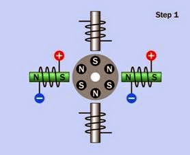
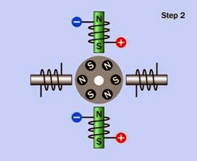
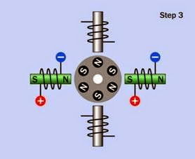
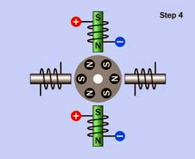
stepper motor What It Does,How It Works,Variants,Values,How to Use it and What Can Go Wrong

Also often referred to as a stepping motor, and sometimes known as a step motor. It is a type of induction motor but merits its own entry in this encyclopedia as it has acquired significant and unique importance in electronics equipment where precise positioning of a moving part is needed and digital control is available.

What It Does

A stepper motor rotates its drive shaft in precise steps in response to a timed sequence of pulses (usually one step per pulse). The pulses are de­ livered to a series of coils or windings in the sta­ tor, which is the stationary section of the motor, usually forming a ring around the rotor, which is the part of the motor that rotates. Steps may also be referred to as phases, and a motor that rotates in small steps may be referred to as having a high phase count.

A stepper motor theoretically draws power for its stator coils at a constant level that does not vary with speed. Consequently the torque tends to decrease as the speed increases, and conversely, it is greatest when the motor is stationary or locked.

The motor requires a suitable control system to provide the sequence of pulses. The control sys­ tem may consist of a small dedicated circuit, or a microcontroller or computer with the addition of suitable driver transistors capable of handling

the necessary current. The torque curve of a mo­ tor can be extended by using a controller that increases the voltage as the speed of the control pulses increases.

Because the behavior of the motor is controlled by external electronics, and its interior is usually symmetrical, a stepper motor can be driven back­ ward and forward with equal torque, and can also be held in a stationary position, although the stator coils will continue to consume power in this mode.

How It Works

The stator has multiple poles made from soft iron or other magnetic material. Each pole is either energized by its own coil, or more commonly, several poles share a single, large coil. In all types of stepper motor, sets of stator poles are mag­ netized sequentially to turn the rotor and can re­ main energized in one configuration to hold the rotor stationary.

The rotor may contain one or more permanent magnets, which interact with the magnetic fields

generated in the stator. Note that this is different from a squirrel-cage AC motor in which a “cage” is embedded in the rotor and interacts with a ro­ tating magnetic field, but does not consist of permanent magnets.

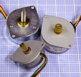
Three small stepper motors are shown in Figure 25-1. Clockwise from the top-left, they are four-wire, five-wire, and six-wire types (this dis­ tinction is explained in the following section). The motor at top-left has a threaded shaft that can engage with a collar, so that as the motor shaft rotates counter-clockwise and clockwise, the collar will be moved down and up.

clip_image006

Figure 25-1. Three small stepper motors.

Reluctance Stepper Motors

The simplest form of stepper motor uses a rotor that does not contain permanent magnets. It re­ lies on the principle of variable reluctance, reluc­ tance being the magnetic equivalent of electrical resistance. The rotor will tend to align its protrud­ ing parts with the exterior source(s) of the mag­ netic field, as this will reduce the reluctance in the system. Additional information about vari­ able reluctance is included in “Reluctance Mo­ tor” (page 197) in the section of this encyclope­ dia dealing with the AC motor.

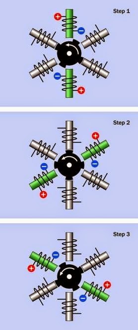
A variable reluctance motor requires an external controller that simply energizes the stator coils sequentially. This is shown in Figure 25-2, where six poles (energized in pairs) are arrayed sym­ metrically around a rotor with four protrusions, usually referred to as teeth. Six stator poles and four teeth are the minimum numbers for reliable performance of a reluctance stepper motor.

In the diagram, the core of each pole is tinted green when it is magnetized, and is gray when it is not magnetized. In each section of this dia­ gram, the stator coils are shown when they have just been energized, and the rotor has not yet had time to respond. External switching to ener­ gize the coils has been omitted for simplicity. In a real motor, the rotor would have numerous ridges, and the clearance between them and the stator would be extremely narrow to maximize the magnetic effect.

In a 6-pole reluctance motor where the rotor has four teeth, each time the controller energizes a new pair of poles, the rotor turns by 30 degrees counter-clockwise. This is known as the step an­ gle, and means that the motor makes 12 steps in each full 360-degree rotation of its shaft. This configuration is very similar to that of a 3-phase AC induction motor, as shown in Figure 23-11 in the AC motor section of this encyclopedia. How­ ever, the AC motor is designed to be plugged into a power source with a constant frequency, and is intended to run smoothly and continuously, not in discrete steps.

Generally, reluctance motors tend to be larger than those with magnetized rotors, and often re­ quire feedback from a sensor that monitors shaft angle and provides this information to control electronics. This is known as a closed loop system. Most smaller stepper motors operate in an open loop system, where positional feedback is con­ sidered unnecessary if the number of pulses to the motor is counted as a means of tracking its position.

clip_image009

Figure 25-2. In a variable reluctance stepper motor, the rotor moves to minimize magnetic reluctance each time the next pair of coils is energized. At each step, the coils have been energized a moment before the rotor has had time to respond.

Permanent Magnet Stepper Motors

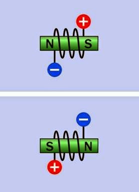
More commonly, the rotor of a stepper motor contains permanent magnets, which require the controller to be capable of reversing the mag­ netic field created by each of the stator coils, so that they alternately attract and repel the rotor magnets.

In a bipolar motor, the magnetic field generated by a coil is reversed simply by reversing the cur­ rent through it. This is shown diagrammatically in Figure 25-3. In a unipolar motor, the magnetic field is reversed by applying positive voltage to the center tap of a coil, and grounding one end or the other. This is shown diagrammatically in Figure 25-4.

clip_image011

Figure 25-3. In a bipolar motor, the magnetic field gener- ated by each stator coil is reversed simply by reversing the current through the coil.

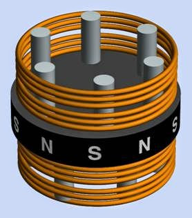
Either type of motor is often designed with an upper and lower deck surrounding a single rotor,
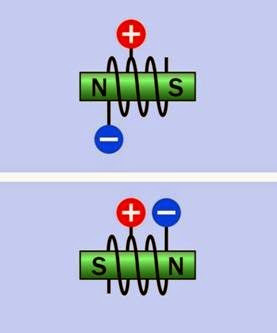
 

clip_image016Figure 25-4. The magnetic field of this coil is reversed by applying positive voltage constantly to a center tap and grounding one end of the coil or the other.

as suggested in Figure 25-5. A large single coil, or center-tapped coil, induces a magnetic field in multiple poles in the top deck, out of phase by one step with a second set of poles, energized by their own coil, in the bottom deck. (All three mo­ tors shown in Figure 25-1 are of this type.) The rotor of the motor is tall enough to span both decks, and is rotated by each of them in turn.

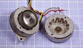
In Figure 25-6, the decks of a two-deck four-wire motor have been split apart. The rotor remains in the left-hand section. It is enclosed within a black cylinder that is a permanent magnet divi­ ded into multiple poles. In the right-hand sec­ tion, a coil is visible surrounding metal “teeth” that function as stator poles when the coil is energized.

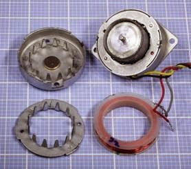
In Figure 25-7, the same motor has been further disassembled. The coil was secured with a length of tape around its periphery, which has been re­ moved to make the coil visible. The remaining

clip_image014

Figure 25-5. A simplified rendering of the common “two deck” type of motor. See text for details.

clip_image018

Figure 25-6. A two-deck stepper motor split open to re- veal its rotor (left) and one of the stators (right) encircled by a coil.

half of the motor, at top-right, contains a second, concealed but identical coil with its own set of poles, one step out of phase with those in the first deck.

Because the field effects in a two-deck stepper motor are difficult to visualize, the remaining di­ agrams show simplified configurations with a minimum number of stator poles, each with its own coil.

clip_image020

Figure 25-7. The stepper motor from the previous figure, further disassembled.

Bipolar Stepper Motors

The most basic way to reverse the current in a coil is by using an H-bridge configuration of switches, as shown in Figure 25-8, where the green arrow indicates the direction of the magnetic field. In actual applications, the switches are solid-state. Integrated circuits are available containing all the necessary components to control a bipolar stepper motor.

Four sequential steps of a bipolar motor are shown in Figure 25-9, Figure 25-10, Figure 25-11, and Figure 25-12. The H-bridge control electronics for each coil are omitted for clarity. As before, energized coils are shown with the pole inside the coil tinted green, while non- energized coils are gray, and the rotor is shown before it has had time to respond to the magnetic field in each step.

Unipolar Motors

The control electronics for a unipolar motor can be simpler than those for a bipolar motor, as off- the-shelf switching transistors can ground one end of the coil or the other. The classic five-wire unipolar stepper motor, often sold to hobbyists and used in robotics projects and similar appli­ cations, can be driven by nothing more elaborate
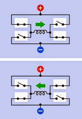
clip_image022Figure 25-8. The simplest and most basic way to reverse the current through a coil is via an H-bridge circuit. In practice, the switches are replaced by solid-state compo- nents.

clip_image024

Figure 25-9. A bipolar stepper motor depicted a moment before the rotor has had time to make its first step in re- sponse to magnetic fields created by the stator coils.

clip_image026

Figure 25-10. The bipolar stepper motor from the previ- ous figure is shown with its rotor having advanced by one step, and coil polarity changed to induce it to make a sec- ond step.

clip_image030

Figure 25-11. The bipolar stepper motor after taking its second step, immediately before making its third step.

than a set of 555 timer chips. However, this type of motor is less powerful for its size and weight because only half of each coil is energized at a time.

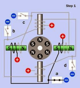
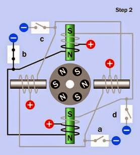
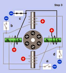
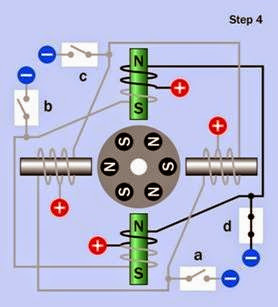
In Figure 25-13, Figure 25-14, Figure 25-15, and Figure 25-16, the simplest configuration of a uni­ polar system is shown in diagrammatic form us­ ing four stator coils and a rotor containing six magnetic poles. Each figure shows the stator coils when they have just been energized, a mo­

clip_image028

Figure 25-12. The bipolar stepper motor after taking its third step. When the rotor responds to the new pattern of magnetic fields, its orientation will be functionally identi- cal with that shown in the first step.

ment before the rotor has had time to move in response to them. Coils that are energized are shown with the metal cores tinted green. Wires that are not conducting current are shown in gray. The open and closed positions of switches a, b, c, and d suggest the path that current is tak­ ing along the wires that are colored black.

Note that coils on opposite sides of the motor are energized simultaneously, while the other pair of coils is de-energized. Adjusting the controller so that it overlaps the “on” cycles of the coils can generate more torque, while consuming more power.

A motor containing more stator poles can ad­ vance in smaller steps, if the poles are separately energized. However, if the coils have individual windings, this will increase the cost of the motor.

Variants

In addition to bipolar and unipolar variants, pre­ viously described, three others are available.

High Phase Count

This term describes any type of stepper motor in which additional poles reduce the step size. The advantages of a high phase count include

clip_image032

Figure 25-13. The coils of this unipolar stepper motor are shown an instant after they have been energized, before the rotor has had time to respond by making its first step.

clip_image036

Figure 25-14. The same motor from the previous figure is shown with coils energized to induce the rotor to make its second step.

clip_image034

Figure 25-15. The same motor from the previous figure is shown with coils energized to induce the rotor to make its third step.

clip_image038

Figure 25-16. When the rotor makes its fourth step, it will be back in an orientation that is functionally identical with the first figure in this series.

smoother running at high speed and greater precision when selecting a desired motor posi­ tion. The additional coils also enable higher pow­ er density, but naturally tend to add to the cost of the motor.

Hybrid

This type of motor uses a toothed rotor that pro­ vides variable reluctance while also containing permanent magnets. It has become relatively common, as the addition of teeth to the rotor enables greater precision and efficiency. From a control point of view, the motor behaves like a regular permanent-magnet stepper motor.

Bifilar

In this type of motor, also sometimes known as a universal stepper motor, two coils are wound in parallel for each stator pole. If there are two poles or sets of poles, and both ends of each winding are accessible via wires that are run out of the motor, there will be eight wires in total. Conse­ quently this type is often referred to as an 8-wire motor.

The advantage of this scheme is that it allows three possible configurations for the internal coils. By shorting together the wires selectively, the motor can be made to function either in uni­ polar or bipolar mode.

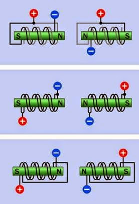
In Figure 25-17, the upper pair of simplified dia­ grams depicts one end of one coil connected to the beginning of the other, while positive voltage is applied at the midpoint, as in a unipolar motor. The magnetic polarity of the coil is determined by grounding either end of the coil. The section of each coil that is not conducting current is shown in gray.

The center pair of diagrams shows the adjacent ends of the coils tied together, so that they are now energized in parallel, with the magnetic po­ larity being determined by the polarity of the voltage, as in a bipolar motor.

The coils may also be connected in series, as shown in the lower pair of diagrams. This will provide greater torque at low speed and lower torque at high speed, while enabling higher- voltage, lower-current operation.

clip_image040

Figure 25-17. In a bifilar motor, two coils are wound in par- allel around each stator pole and can be connected with a center tap to emulate a unipolar motor (upper diagrams), or can be energized in parallel (middle diagrams) or series (lower diagrams) to emulate a bipolar motor.

Multiphase

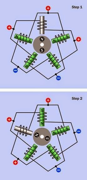
In a multiphase motor, multiple stator coils are usually connected in series, with a center tap ap­ plied between each pair. A possible configura­ tion is shown in Figure 25-18, where the two di­ agrams show two consecutive steps in rotation, although the step angle could be halved by changing the voltage polarity in only one loca­ tion at a time. The way in which the motor is wired

enables only one stator coil to be unpowered during any step, because its two ends are at equal potential. Therefore this type of motor is capable of high torque in a relatively small format.

In some multiphase motors, additional wires al­ low access to both ends of each coil, and the coils are not connected internally. This allows control of the motor to be customized.

Microstepping

An appropriately designed stepper motor can be induced to make very small, intermediate steps if the control voltage is modulated to intermedi­ ate levels. Step angles as low as 0.007 degrees are claimed by some manufacturers. However, a mo­ tor running in this mode is less able to generate torque.

The simplest form of microstepping is half- stepping. To achieve this in a unipolar motor, each coil passes through an “off” state before its magnetic polarity is reversed.

Sensing and Feedback

So long as the series of pulses to the motor allows the rotor ample time to respond, no feedback mechanism from the rotor is necessary to con­ firm its position, and an open-loop system is suf­ ficient. If sudden acceleration, deceleration, load fluctuations, and/or rotation reversal will occur, or if high speeds are involved, a closed loop sys­ tem, in which a sensor provides positional feed­ back, may be necessary.

Voltage Control

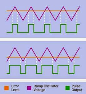
Rapid stepping of a motor requires rapid creation and collapse of magnetic fields in the stator windings. Therefore, self-inductance of the windings can limit the motor speed. One way to overcome this is to use a higher voltage. A more sophisticated solution is to use a controller that provides a high initial voltage, which is reduced or briefly interrupted when a sensor indicates that coil current has increased sufficiently to overcome the self-inductance of the windings

clip_image042

Figure 25-18. A multiphase stepper motor. By applying voltage in the pattern shown, only one coil is not ener- gized during each step. This enables high torque com- pared with the size of the motor.

and has reached its imposed limit. This type of controller may be referred to as a chopper drive as the voltage is “chopped,” usually by power transistors. It is a form of pulse width modulation.

Values

The step angle of a stepper motor is the angular rotation of its shaft, in degrees, for each full step. This will be determined by the physical construc­ tion of the motor. The coarsest step angle is 90 degrees, while sophisticated motors may be ca­ pable of 1.8 degrees (without microstepping).

The maximum torque that a motor can deliver is discussed in “Values” (page 184) in the DC mo­ tor entry of this encyclopedia.

Motor weight and size, shaft length, and shaft diameter are the principal passive values of a stepper motor, which should be checked before it is selected for use.

How to Use it

• Cheap controller hardware where open- loop applications are acceptable

• High reliability, since no brushes or commu­ tator are involved

Disadvantages include:

• Noise and vibration

• Resonance at low speeds

• Progressive loss of torque at high speeds

Protection Diodes

While a small stepper motor may be driven di­ rectly from power transistors, darlington pairs, or even 555 timers, larger motors will create back- EMF when the magnetic field of each stator coil

is induced or forward EMF when the field is al­

Stepper motors are used to control the seek ac­ tion in disk drives, the print-head movement and paper advance in computer printers, and the scanning motion in document scanners and cop­ iers.

Industrial and laboratory applications include the adjustment of optical devices (modern tele­ scopes are often oriented with stepper motors), and valve control in fluid systems.

A stepper motor may be used to power a linear actuator, usually via a screw thread (properly known as a lead screw) or worm gear. For more on linear actuators, see “Linear Actuator” (page 184). While the stepper motor will enable greater accuracy than a traditional DC motor, the gearing inevitably will introduce some imprecision.

Advantages of stepper motors include:

• Precise positioning, typically within 3 per­ cent to 5 percent per step. The percentage step error does not accumulate as the motor rotates

• Able to run at a wide range of speeds, in­ cluding very slow speeds without reduction gearing

• Trouble-free start, stop, and reverse action

lowed to collapse, and bipolar motors will also induce voltage spikes when the current reverses. In a unipolar motor, while only one-half of the coil is actually energized via its center tap, the other half will have an induced voltage, as the coil acts like a linear transformer.

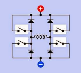
A simplified schematic illustrating diode place­ ment for a bipolar motor is shown in Figure 25-19.

clip_image045

Figure 25-19. The H-bridge circuit must be augmented with protection diodes to guard against back-EMF created by fluctuating current in the stator coil.

Integrated circuit chips are available taht incor­ porate protection diodes, in addition to the nec­ essary power transistors. Stepper motors may al­ so have protection diodes built in. Consult the manufacturer’s datasheet for details before at­ taching a motor to a power source.

Positional Control

The built-in control electronics of a servo mo­ tor typically turn the shaft to a precisely known position in response to pulse-width modulation from an exterior source such as a microcontrol­ ler, whereas the angle of rotation of a stepper motor in an open-loop system must be calcula­ ted by counting the number of steps from an in­ itial, home position. This limitation of a stepper motor can be overcome by using a closed-loop system, but that will require monitoring the mo­ tor, adding complexity to the external controller. The choice between stepper and servo motors should be evaluated on a case-by-case basis.

What Can Go Wrong

General problems affecting all types of motors are listed in “Heat effects” (page 188). Issues re­ lating more specifically to stepper motors are lis­ ted in the following sections.

Incorrect Wiring

Because a stepper motor is driven via multiple conductors, there is a significant risk of wiring errors, especially since many motors are not iden­ tified with part numbers. The first challenge, then, may be to determine what type of motor it is. When the motor is disconnected from any power, and the shaft is rotated with finger and thumb, a magnetized-rotor motor will not spin as freely as a reluctance motor, because the mag­ nets in the rotor will provide intermittent turning resistance.

If a unipolar motor is relatively small and is fitted with five wires, almost certainly the motor con­ tains two coils, each with a center tap, and their function can be determined by applying positive

voltage to the red wire and grounding each of the other wires in turn. Attaching a small piece of tape to the motor shaft will assist in viewing its orientation.

A multimeter set to measure ohms can also be useful in deducing the internal coil connections of the motor, since the end-to-end resistance of a coil should be approximately twice the resist­ ance between the center tap and either end of the coil.

A multiphase motor may have five wires, but in this case, the resistance between any two non- adjacent wires will be 1.5 times the resistance between any two adjacent wires.

Step Loss

In an open-loop system, if the motor skips or misses pulses from the controller, the controller no longer has an accurate assessment of the shaft angle. This is known as step loss. Since this can be caused by sudden changes in control fre­ quency, the frequency should be increased (or decreased) gradually. This is known as ramping the motor speed. Stepper motors cannot re­ spond instantly to changes in speed, because of inertia in the rotor or in the device that the motor is driving.

Where the motor turns one or more steps beyond its commanded stopping point, this is known as overshoot.

Step loss may also occur if the motor continues turning after power has been interrupted (either intentionally or because of an external fault). In an open-loop system, the controller should be designed to reset the motor position when pow­ er is initiated.

Excessive Torque

When the motor is stationary and not powered, detent torque is the maximum turning force that can be applied without causing the shaft to turn. When the motor is stationary and the controller does deliver power to it, holding torque is the maximum turning force that can be applied

without causing the shaft to turn, and pull-in tor­ que is the maximum torque which the motor can apply to overcome resistance and reach full speed. When the motor is running, pull-out tor­ que is the maximum torque the motor can deliver without suffering step loss (pulling it out of sync with its controller). Some or all of these values should be specified on the motor’s datasheet. Exceeding any of them will result in step loss.

Hysteresis

When a controller directs a stepper motor to seek a specified position, the term hysteresis is often used to mean the total error between the actual position it reaches when turning clockwise, and the actual position it reaches when turning counter-clockwise. This difference may occur be­ cause a stepper motor tends to stop a fraction short of its intended position, especially under significant load. Any design that requires preci­ sion should be tested under real-world condi­ tions to assess the hysteresis of the motor.

Resonance

A motor has a natural resonant frequency. If it is stepped near that frequency, vibration will tend to be amplified, which can cause positional er­ rors, gear wear (if gears are attached), bearing wear, noise, and other issues. A good datasheet should specify the resonant frequency of the motor, and the motor should run above that fre­ quency if possible. The problem can be ad­ dressed by rubber motor mounts or by using a resilient component, such as a drive belt, in con­ junction with the drive shaft. Damping the vibra­ tion may be attempted by adding weight to the motor mount.

Note that if the motor has any significant weight attached directly to its shaft, this will lower its resonant frequency, and should be taken into account.

Resonance may also cause step loss (see preced­ ing sections).

Hunting

In a closed-loop system, a sensor on the motor reports its rotational position to the controller, and if necessary, the controller responds by ad­ justing the position of the motor. Like any feed­ back system, this entails some lag time, and at certain speeds the motor may start hunting or oscillating as the controller over-corrects and must then correct its correction. Some closed- loop controllers avoid this issue by running most­ ly in open-loop mode, using correction only when the motor experiences conditions (such as sudden speed changes), which are likely to cause step loss.

Saturation

While it may be tempting to increase the torque from a stepper motor by upping the voltage (which will increase the current through the sta­ tor coils), in practice motors are usually designed so that the cores of the coils will be close to sat­ uration at the rated voltage. Therefore, increas­ ing the voltage may achieve very little increase in power, while causing a significant increase in heat.

Rotor Demagnetization

The permanent magnets in a rotor can be parti­ ally demagnetized by excessive heat. Demag­ netization can also occur if the magnets are ex­ posed to high-frequency alternating current when the rotor is stationary. Therefore, attempt­ ing to run a stepper motor at high speed when the rotor is stalled can cause irrevocable loss of performance.
 

unijunction transistor What It Does,How It Works,Variants,Values,How to Use it and What Can Go Wrong

The unijunction transistor (UJT) and programmable unijunction transistor (PUT) are dif­ferent internally, but are sufficiently similar in function to be combined in this entry.

What It Does

Despite their names, the unijunction transistor (UJT) and programmable unijunction transistor (PUT) are not current-amplification devices like bipolar transistors. They are switching components that are more similar to diodes than to transistors.

The UJT can be used to build low- to mid- frequency oscillator circuits, while the PUT pro­ vides similar capability with the addition of more sophisticated control, and is capable of function­ ing at lower currents. The UJT declined in popularity during the 1980s after introduction of com­ponents such as the 555 timer, which offered more flexibility and a more stable output fre­quency, eventually at a competitive price. UJTs are now uncommon, but PUTs are still available in quantity as through-hole discrete compo­nents. Whereas an integrated circuit such as a 555 timer generates a square wave, unijunction transistors in oscillator circuits generate a series of voltage spikes.

The PUT is often used to trigger a thyristor (de­ scribed in Volume 2) and has applications in low- power circuits, where it can draw as little as a few Mmicroamps.

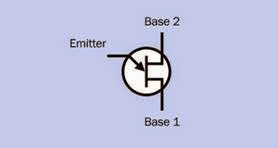
Schematic symbols for the two components are shown in Figure 27-1 and Figure 27-2. Although the symbol for the UJT is very similar to the sym­bol for a field-effect transistor (FET), its behavior is quite different. The bent arrow identifies the UJT, while a straight arrow identifies the FET. This difference is of significant importance.

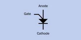
The schematic symbol for a PUT indicates its function, as it resembles a diode with the addi­tion of a gate connection.

clip_image005

Figure 27-1. Schematic symbol for a unijunction transistor (UJT). Note the bent arrow. The symbol for a field- effect transistor looks similar, but has a straight arrow. The functionality of the two components is very different.

In Figure 27-3, the transistors at left and center are old-original unijunction transistors, while the one at right is a programmable unijunction transistor. (Left: Maximum 300mW, 35V inter­ base voltage. Center: 450mW, 35V interbase volt­ age. Right: 300mW, 40V gate-cathode forward voltage, 40V anode-cathode voltage.)

clip_image007

Figure 27-2. Schematic symbol for a programmable unijunction transistor (PUT). The symbol accurately suggests the similarity in function to a diode, with the addition of a gate to adjust the threshold voltage.

clip_image009

Figure 27-3. The unijunction transistors at left and center are becoming obsolete; the one at the right is a program- mable unijunction transistor (PUT), still readily available and widely used as a thyristor trigger.

How It Works

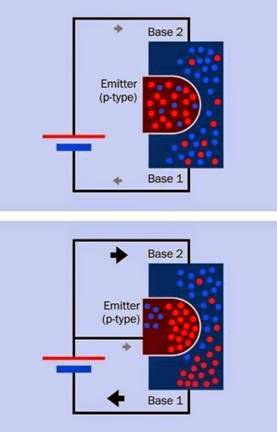
The UJT is a three-terminal semiconductor de­ vice, but contains only two sections sharing a single junction—hence its name. Leads attached to opposite ends of a single channel of N-type semiconductor are referred to as base 1 and base 2, with base 2 requiring a slightly higher potential than base 1. A smaller P-type insert, midway be­ tween base 1 and base 2, is known as the emitter.

The diagram in Figure 27-4 gives an approximate idea of internal function.

When no voltage is applied to the emitter, a rel­atively high resistance (usually more than 5K) prevents significant current flow from base 2 to base 1. When the positive potential at the emitter increases to a triggering voltage (similar to the junction threshold voltage of a forward-biased di­ ode), the internal resistance of the UJT drops very rapidly, allowing current to enter the component via both the emitter and base 2, exiting at base

1. (The term “current” refers, here, to convention­ al current; electron flow is opposite.) Current flowing from base 2 to base 1 is significantly greater than current flowing from the emitter to base 1.

clip_image012

Figure 27-4. Internal workings of a unijunction transistor.

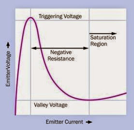
The graph in Figure 27-5 outlines the behavior of a UJT. As the voltage applied to the emitter in­ creases, current flowing into the component from the emitter increases slightly, until the trig­ gering voltage is reached. The component’s in­ternal resistance now drops rapidly. This pulls down the voltage at the emitter, while the cur­ rent continues to increase significantly. Because of the drop in resistance, this is referred to as a negative resistance region. The resistance actual­ ly cannot fall below zero, but its change is nega­tive. After emitter voltage drops to a minimum known as the valley voltage, the current contin­ues to increase with a small increase in voltage. On datasheets, the peak current is often referred to as Ip while valley current is Iv.

clip_image015

Figure 27-5. Response curve of a unijunction transistor (UJT). When positive potential at the emitter reaches the triggering voltage, internal resistance drops radically and the component goes through a phase known as “negative resistance” as current increases.

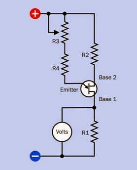
Figure 27-6 shows a test circuit to demonstrate the function of a UJT, with a volt meter indicating its status. A typical supply voltage would range from 9VDC to 20VDC.

clip_image017

Figure 27-6. A test circuit for a unijunction transistor (UJT) using a volt meter to show its response as a potentiometer increases the voltage applied to its emitter.

A PUT behaves similarly in many ways to a UJT but is internally quite different, consisting of four semiconducting layers and functioning similarly to a thyristor.

The PUT is triggered by increasing the voltage on the anode. Figure 27-7 shows a test circuit for a PUT. This component is triggered when the volt­ age at its anode exceeds a threshold level, while the gate sets the threshold where this occurs. When the PUT is triggered, its internal resistance drops, and current flows from anode to cathode, with a smaller amount of current entering through the gate. This behavior is almost identi­cal to that of a forward-biased diode, except that the threshold level can be controlled, or “pro­grammed,” according to the value of the positive potential applied at the gate, with R1 and R2 es­tablishing that potential by functioning as a volt­ age divider.

clip_image020

Figure 27-7. A test circuit for a programmable unijunction transistor (PUT) using a volt meter to show its response as a potentiometer increases the voltage applied to its anode.

The voltage output of a PUT follows a curve that is very similar to that shown in Figure 27-5, al­ though current and voltage would be measured at the cathode.

Variants

PUTs and UJTs are not made as surface-mount components.

UJTs are usually packaged in black plastic, al­ though older variants were manufactured in cans. PUTs are almost all packaged in black plas­ tic. With the leads pointing downward and the flat side facing toward the viewer, the lead func­tions of a PUT are usually anode, gate, and cath­ode, reading from left to right.

Values

The triggering voltage of a UJT can be calculated from the values of R1 and R2 in Figure 27-7 and the voltage at base 1. The term Rbb is often used to represent the sum of R1 + R2, with Vbb repre­ senting the total voltage across the two resistors (this is the same as the supply voltage in Figure 27-6). Vt, the triggering voltage, is given by:

Vt = Vbb * (R1 / Rbb)

The term (R1/Rbb) is known as the standoff ratio, often represented by the Greek letter ƍ.

Typically the standoff ratio in a UJT is at least 0.7, as R1 is chosen to be larger than R2. Typical values for R1 and R2 could be 180Ω and 100Ω, respec­tively. If R4 is 50K and a 100K linear potentiometer is used for R3, the PUT should be triggered when the potentiometer is near the center of its range. The emitter saturation voltage is typically from 2V to 4V.

If using a PUT, typical values in the test circuit could be supply voltage ranging from 9VDC to 20VDC, with resistances 28K for R1 and 16K for R2, 20Ω for R5, 280K for R4, and a 500K linear po­ tentiometer for R3. The PUT should be triggered when the potentiometer is near the center of its range.

Sustained forward current from anode to cath­ode is usually a maximum of 150mA, while from gate to cathode the maximum is usually 50mA. Power dissipation should not exceed 300mW. These values should be lower at temperatures above 25 degrees Centigrade.

Depending on the PUT being used, power con­sumption can be radically decreased by upping the resistor values by a multiple of 100, while supply voltage can be decreased to 5V. The cath­ ode output from the PUT would then be connec­ted with the base of an NPN transistor for ampli­fication.


How to Use it

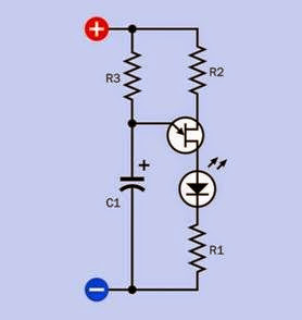
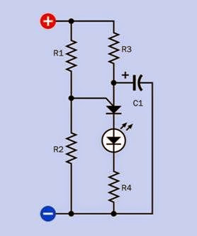
Figure 27-8 shows a simple oscillator circuit built around a UJT, Figure 27-9 shows a comparable circuit for a PUT. Initially the supply voltage charges the capacitor, until the potential at the emitter of the UJT or the gate of the PUT reaches the threshold voltage, at which point the capac­itor discharges through the emitter and the cycle repeats. Resistor values would be similar to those used in the test circuits previously described, while a capacitor value of 2.2μF would provide a visible pulse of the LED. Smaller capacitor values would enable faster oscillation. In the PUT circuit, adjusting the values of R1 and R2 would allow fine control of triggering the semiconductor.

clip_image022

Figure 27-8. A basic oscillator circuit using a unijunction transistor (UJT). As the capacitor accumulates charge, the voltage on the emitter increases until it triggers the UJT, at which point the capacitor discharges through the emitter.

Probably the most common use for a PUT at this time is to trigger a thyristor.

clip_image024

Figure 27-9. A basic oscillator circuit using a programmable unijunction transistor (PUT). As the capacitor accumulates charge, the voltage on the anode increases until it triggers the PUT, at which point the capacitor discharges through the anode. The gate voltage is preset by R1 and R2 to adjust the triggering voltage.

What Can Go Wrong
Name Confusion

A programmable unijunction transistor (PUT) is sometimes referred to simply as a “unijunction transistor” (UJT). Bearing in mind the totally dif­ferent modes of operation of UJT and PUT, the PUT should always be identified by its acronym or by its full name. A circuit will not function if a UJT is substituted for a PUT, or a PUT is substitu­ted for a UJT.

Incorrect Bias

Neither the UJT nor the PUT is designed to oper­ate with reverse bias. In the UJT, a small forward bias should be applied from base 2 to base 1 (that is, base 2 should be at a higher potential relative to base 1) regardless of the voltage on the emit­ ter. The emitter voltage may vary from 0 volts

What Can Go Wrong


upward. The PUT must be forward biased be­ tween its anode and cathode (the anode must have a higher potential relative to the cathode), with an intermediate positive voltage at the gate established by resistors R1 and R2 functioning as a voltage divider (see Figure 27-7). Failure to ob­serve correct biasing will result in unpredictable behavior and possible damage to the component.


Overload

Like any semiconductor, the UJT and the PUT must be protected from excessive current, which can burn out the component. Never connect ei­ther of these components directly across a power source without appropriate resistances to limit current flow. Maximum continuous power dissi­pation for UJTs and PUTs is usually 300mW.


servo motor What It Does,How It Works,Variants,Values,How to Use it and What Can Go Wrong


Should be referred to as an RC servo if it is intended for use in small devices that are remote-controlled and battery powered. However, in practice, the RC acronym is often omitted.

What It Does

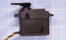
A servo motor is actually a combination of a motor, reduction gearing, and miniaturized control electronics, usually packaged together inside a very compact sealed plastic case. The motor itself may be AC or DC, and if DC, it may be brushed or brushless. What distinguishes a servo from other types of motor is that it is not designed for con­tinuous rotation. It is a position-seeking device. Its rotational range may be more than 180 de­grees but will be significantly less than 360 de­grees. Two typical RC servos are shown in Figure 24-1. A side view of a motor is shown in Figure 24-2.

The electronics inside the motor enclosure inter­pret commands from an external controller. The command code specifies the desired turn angle measured as an offset either side of the center position of the motor’s range. The motor turns quickly to the specified position and stops there. So long as the command signal continues and power to the motor is sustained, the motor will hold its position and “push back” against any ex­ternal turning force. In the absence of such a force, while the motor is stationary, it will use very little current.

clip_image004

Figure 24-1. A typical RC servo motor is capable of more than 50 inch-ounces of torque yet can be driven by three or four AA alkaline cells in series, and weighs under 2 oun- ces.

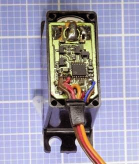
The electronics inside a typical RC servo motor are shown in Figure 24-3.

How It Works

Servo motors are generally controlled via pulse- width modulation (PWM).

clip_image008

Figure 24-2. RC servo motors are mostly similar in size. This is a typical side view.

An industrial servo typically requires a controller that is an off-the-shelf item sold by the manu­facturer of the motor. The encoding scheme of the control signals may be proprietary. A heavy- duty servo may be designed to run from three- phase power at a relatively high voltage, and may be used in applications such as production-line automation.

The remainder of this encyclopedia entry will fo­cus primarily on small RC servos rather than in­ dustrial servos.

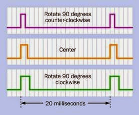
For small RC servos, the stream of control pulses is at a constant frequency of 20ms, with the pos­itive durations of each pulse being interpreted as a positioning command to the motor, and the gaps between the pulses being disregarded. A typical range of pulse widths for a small motor is 1ms to 2ms, specifying a range of -90 to +90 de­ grees either side of a center location. Many modern motors are capable of excursions be­ yond these limits, and can be calibrated to es­tablish the precise relationship between pulse width and turn angle. The motor can then be controlled by a lookup table in microcontroller software, or by using a conversion factor be­ tween degree-angle and pulse width.

Figure 24-4 shows the typical range of pulse widths within the fixed 20ms period (a frequency of 50Hz) between the start of one pulse and the

start of the next, and the meaning of each pulse width to the servo motor. Intermediate pulse widths are interpreted as instructions to rotate to intermediate positions.

clip_image010

Figure 24-3. The electronics inside a servo motor decode a stream of pulses that specify the turn angle of the motor.

Small servo motors require the user to provide a controller that will conform with the above spec­ ification. This is often achieved by programming a microcontroller, and some microcontroller chips make this especially easy by providing a PWM output specifically tailored to the require­ ments of an RC servo. Either way, the microcon­troller can be directly connected to the servo, enabling an extremely simple and flexible way to manage a positioning device.

Alternatively, a simple pulse generator such as a 555 timer chip can be used, or controller boards are available from hobbyist supply sources. Some controller boards have USB connections enabling a servo to be governed by computer software.

clip_image013

Figure 24-4. The turn angle of a small RC servo motor is determined by a pulse width from a controller ranging from 1ms to 2ms in duration. The frequency of the pulses is constant at 50Hz.

In Figure 24-5, a schematic illustrates the con­nection of a 555 timer with an RC servo, with component values to create a constant frequen­ cy of about 48Hz (slightly more than 20ms from peak to peak). The 1μF capacitor in the circuit charges through the 2.2K resistor in series with the diode, which bypasses the 28K resistor. This charging time represents the “on” cycle of the timer chip. The capacitor discharges through the 28K resistor, representing the “off” cycle. The 1K potentiometer, in series with the 5K resistors, acts as a voltage divider applied to the control pin of the timer, adjusting the timer’s charge and dis­ charge thresholds. Turning the potentiometer will lengthen or shorten the “on” time of each cycle, without changing the frequency. In prac­ tice, because capacitors are manufactured with wide tolerances, the frequency of the timer out­ put cannot be guaranteed. Fortunately most ser­vos will tolerate some inaccuracy.

Since the motor shares the power supply of the timer in this circuit, a protection diode and ca­pacitor have been added between the power supply to the motor and negative ground, to suppress noise and back-EMF.

clip_image015Figure 24-5. An RC servo can be controlled via a 555 timer with appropriate component values. The potentiometer determines the angular position of the servo.

Inside a servo motor’s casing, the electronics in­ clude a potentiometer that turns with the output shaft, to provide feedback confirming the motor’s position. The limited turning range of the potentiometer determines the turn limits of the motor output shaft.

Variants

Small servos may contain brushed or brushless DC motors. Naturally the brushless motors have greater longevity and create less electrical noise. See the DC motor entry in this encyclopedia for a discussion of brushed versus brushless motors.

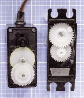
Servos may use nylon, “Karbonite,” or metal re­ duction gearing. The nylon gears inside a cheap­ er RC servo are shown in Figure 24-6.

Brushless motors and metal gears add slightly to the price of the motor. Metal gears are stronger than nylon (which can crack under load) but may wear faster, leading to backlash and inaccuracy in the gear train. The friction between nylon-to- nylon surfaces is very low, and nylon is certainly


clip_image018

Figure 24-6. Nylon gearing inside a servo motor.

adequate and may be preferable if a servo will not be heavily loaded. “Karbonite” is claimed to be five times stronger than nylon and may be a satisfactory compromise. If a gear set experien­ces a failure (for example, teeth can be stripped as a result of excessive load), manufacturers usu­ally will sell a replacement set to be installed by the user. Installation requires manual dexterity and patience, and some skill.

Servos may have roller bearings or plain sintered bearings, the latter being cheaper but much less durable under side loading.

So-called digital servos use faster internal elec­tronics than the older, so-called analog servos, and because they sample the incoming pulse stream at a higher frequency, they are more re­ sponsive to small, rapid commands from the con­troller. For this reason they are preferred by hob­ byists using servos to control the flight of model airplanes. Externally, the control protocol for dig­ ital and analog servos is the same, although a

digital servo can be reprogrammed with new code values establishing the limits to its range. A standalone programming unit must be pur­chased to achieve this.

The most popular manufacturers of small servo motors are Futaba and Hitec. While their control protocols are virtually identical, the motor out­ put shafts differ. The shaft is typically known as the spline, and is grooved to fit push-on attach­ ments. The spline of a Futaba motor has 25 grooves, while Hitec uses 24 grooves. Attach­ ments must be appropriate for the brand of mo­ tor that has been chosen.

Values

A small servo typically weighs 1 to 2 ounces, has a rotation time of 1 to 2 seconds from one end of its travel to the other, and can exert a surprisingly robust torque of 50 ounce-inches or greater.

Voltage

Small servos were originally designed to run from 4.8V rechargeable batteries in model aircraft. They can be driven with 5VDC to 6VDC on a routine basis. A few servos are designed for higher voltages.

Amperage

The datasheets provided by most manufac­turers often fail to specify the power that a servo will draw when it is exerting maximum torque (or indeed, any torque at all). Since small servos are often driven by three or four AA alkaline batteries in series, the maximum current draw is unlikely to be much greater than 1 amp. When the motor is energized but not turning, and is not resisting a turning force, its power consumption is negligible. This feature makes servos especially desira­ble for remote-controlled battery-powered devices.

Some motors that have a turning range exceed­ing 180 degrees will respond to pulses of less than 1ms or greater than 2ms. A newly acquired motor should be tested with a microcontroller


that steps through a wide range of pulse dura­tions, to determine the limits empirically. Pulses that are outside the motor’s designed range will generally be ignored and will not cause damage.

The turn rate or transit time specified in a data­ sheet is the time a servo takes to rotate through 60 degrees, with no load on the output shaft. A high-torque servo generally achieves its greater turning force by using a higher reduction gear ratio, which tends to result in a longer transit time.

How to Use it

Typical applications for a small servo include ro­tating the flaps or rudder of a model aircraft, steering a model boat, model car, or wheeled ro­bot, and turning robotic arms.

A servo generally has three wires, colored red (power supply), black or brown (ground), and or­ange, yellow, or white (for the pulse train from the controller). The ground wire to the motor must be common with the ground of the con­troller, and consequently a ceramic bypass ca­pacitor of 0.1μF or 0.01μF should be placed be­ tween the (red) power wire to the motor and ground. A protection diode should also be used. Neither a diode nor a capacitor should be attach­ed to the wire carrying control signals, as it will interfere with the pulse train.

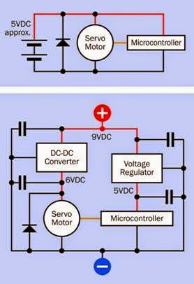
When powering the motor, an AC adapter should only be used with some caution, as its power output may be inadequately smoothed. A volt­ age regulator is not necessary, but bypass capacitors are mandatory. Figure 24-7 shows two hypothetical schematics. The upper section of the figure shows a battery-driven system, possi­bly using four 1.2V NiMH rechargeable batteries. Since batteries do not generally create voltage spikes, no capacitors are used, but a diode is in­cluded to protect the microcontroller from EMF when the servo stops and starts. The lower sec­tion of the figure shows the additional precau­tions that may be necessary when using DC pow­er from an AC adapter. The DC-DC converter,

which derives 6VDC for the motor requires smoothing capacitors (this should be specified in its datasheet), and so does the voltage regu­lator, which delivers regulated 5VDC power to the microcontroller. Once again, the protection diode is included. In both diagrams, the orange wire represents the control wire transmitting pul­ses to the servo motor.

clip_image020

Figure 24-7. Two possible schematics to run a small servo motor, the upper example using battery power (for example, from four 1.2V NiMH cells) and the lower example us- ing a 9VDC AC adapter. See text for additional explanation.

Various shaft attachments are available from the same online hobby-electronics suppliers that sell servos. The attachments include discs, single arms, double arms, and four arms in a cross- shaped configuration. A single-arm attachment is often known as a horn, and this term may be applied loosely to any kind of attachment. The

horn is usually perforated so that other compo­nents can be fixed to it by using small screws or nuts and bolts. Figure 24-8 shows a variety of horns.

clip_image022

Figure 24-8. Various shaft attachments, known as horns, are available from motor manufacturers. The blue one is metallic; the others are plastic.

After the horn is pushed onto the spline (the mo­tor shaft), it is held in place with one central screw. As previously noted, the two major man­ ufacturers of small servos, Futaba and Hitec, have incompatible splines.

Modification for Continuous Rotation

It is possible to modify a small servo motor so that it will rotate continuously.

First the motor case must be opened, and the potentiometer must be centered by using a controller to send some 1.5ms pulses. The potenti­ometer must then be glued or otherwise secured with its wiper in this precise center position, after which the potentiometer is disconnected from the drive train.

Mechanical stops that would limit the rotation of the motor shaft must be cut away, after which the motor is reassembled. Because the potenti­ometer has been immobilized, the motor’s inter­ nal electronics will now “see” the shaft as being in its center position at all times. If the controller sends a pulse instructing the motor to seek a po­sition clockwise or counter-clockwise from cen­ ter, the motor will rotate in an effort to reach that

position. Because the potentiometer will not provide feedback to signal that the motor has achieved its goal, the shaft will continue to rotate indefinitely.

In this mode, the primary distinguishing charac­teristic of the servo has been disabled, in that it can no longer turn to a specific angle. Also, stop­ ping the servo may be problematic, as it must receive a command that precisely matches the fixed position of the potentiometer. Since the potentiometer may have moved fractionally dur­ing the process in which it was immobilized, some trial and error may be needed to determine the pulse width that corresponds with the po­tentiometer position.

The purpose of modifying a servo for continuous rotation is to take advantage of its high torque, small size, light weight, and the ease of control­ ling it with a microcontroller.

In response to the interest shown by hobbyists in modifying servos for continuous rotation, some manufacturers now market servos with continuous rotation as a built-in feature. Typical­ ly they include a trimmer potentiometer to cali­ brate the motor, to establish its center-off posi­tion.

What Can Go Wrong
Incorrect Wiring

The manufacturer’s datasheet should be checked to confirm the color coding of the wires. While a simple DC motor can be reversed by in­ verting the polarity of its power supply, this is totally inappropriate for a servo motor.

Shaft/Horn Mismatch

Attachments for the spline of one brand of motor may not fit the spline of another brand, and can­ not be forced to fit.

Unrealistically Rapid Software Commands

Microcontroller software that positions a servo must allow sufficient time for the servo to re­spond before the software specifies a new posi­ tion. It may be necessary to insert delay loops or other wait times in the software.

Jitter

A servo arm that twitches unpredictably usually indicates that the pulse train is being corrupted by external electrical noise. The control wire to the servo should be as short as possible, and should not run closely adjacent to conductors carrying AC or high frequency current switching, or control wires for other servo motors.

Motor Overload

A servo capable of delivering 2 lbs of force 1 inch from its shaft can easily generate enough torque, when it stalls, to break itself free from its mounts, or bend or break any arm or linkage attached to its shaft. Ideally, a relatively “weak link” should be included so that if breakage occurs, it will be pre­dictable and will be relatively easy and cheap to repair.


Unrealistic Duty Cycle

Small servos are designed for intermittent use. Constant cycling will cause wear and tear, espe­cially if the motor has a brushed commutator or metal reduction gears.

Electrical Noise

Brushed motors are always a source of electrical interference, and any servo will also tend to cre­ate a voltage dip or surge when it starts and stops. A protection diode may be insufficient to isolate sensitive microcontrollers and other inte­grated circuit chips. To minimize problems, the servo can be driven by a source of positive volt­ age that is separate from the regulated power supply used by the chips, and larger filter capac­itors may be added to the voltage supply of the microcontroller. A common ground between the motor and the chips is unfortunately unavoidable.


solenoid What It Does,How It Works,Variants,Values,How to Use it,What Can Go Wrong

The term solenoid was historically used to describe any coil without a magnetic core. More recently and more commonly it describes a coil inside of which a cylindrical plunger moves in response to the magnetic field generated by the coil. In this encyclopedia, the term electromagnet has its own entry, and describes a coil with a center component of ferromagnetic material that does not move relative to the coil. It is used solely to attract or repel other parts that have inherent magnetic properties. By comparison, the induc­tor entry describes a coil that is used for the specific purpose of creating reactance, or self-inductance, in an electronic circuit, often in association with alternating current and in combination with resistors and/or capacitors. The inductor entry contains a basic discussion and explanation of magnetic force created by electricity.

What It Does

A typical solenoid consists of a hollow coil inside a frame, which may be a sealed cylinder or box- shaped with open sides. In the case of a cylinder, its opposite ends may be referred to as pole faces.

At least one of the pole faces has a hole through which a plunger (also known as an armature) is pulled or pushed by the solenoid. Thus, the sol­enoid is a device for applying a linear mechanical force in response to current passing through it. In most solenoids, current must be maintained in order to maintain the mechanical force.

A small open-frame solenoid is pictured in Figure 21-1. The upper section of the figure shows the three basic parts: frame, compression spring, and plunger. The lower part of the figure shows the parts assembled.

A larger, closed, cynlindrical solenoid is shown in Figure 21-2, with the plunger and spring re­ moved.

A 3D rendering showing a simplified, imaginary, cylindrical solenoid cut in half appears in Figure 21-3. The diagram includes a gray cylin­drical shell, often described as the frame; the coil, shown in orange; the plunger, which is pulled in­ to the coil by its magnetic field; and the triangular stop, which limits the plunger’s upward travel. The frame of the solenoid exists not merely to protect the coil, but to provide a magnetic circuit, which is completed through the plunger.

The lower end of the plunger is often fitted with a nonmagnetic yoke or perforated plate for con­ nection with other components. Stainless steel can be used for this purpose. The stop may be fitted with a thrust rod (also fabricated from stainless steel) if the solenoid is intended to “push” as well as “pull.” Springs to adjust the force of the plunger, or to return it to its initial position when the current through the coil is interrupted, are not shown in the rendering.

clip_image005

Figure 21-1. A small 12VDC solenoid.

clip_image007

Figure 21-2. A larger solenoid rated for 24VDC.

Because there is no standardized schematic sym­bol for a solenoid, and because this type of com­ponent is so widely used in conjunction with valves, any diagram involving solenoids is more likely to emphasize fluid or gas flow with symbols that have been developed for that purpose. In such circuits, a solenoid may be represented sim­ply by a rectangle. However, the symbols shown in Figure 21-4 may occasionally be found.

How It Works

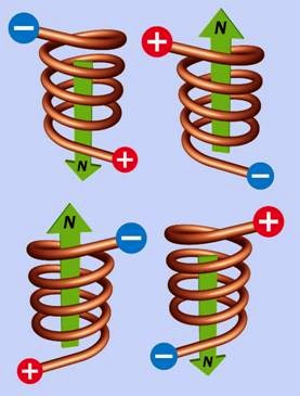
Current flowing through the coil creates a mag­netic force. This is explained in the inductor en­ try of this encyclopedia, using diagrams in Figure 14-3, Figure 14-4, Figure 14-5, and

Figure 14-6.

If the plunger is fabricated from a material such as soft iron, the coil will induce an equal and op­ posite magnetic polarity in the plunger. Conse­quently the plunger will attempt to occupy a po­ sition inside the coil where the ends of the plung­er are equal distances from the ends of the coil. If a collar is added to the free end of the plunger, this can increase the pulling force on the plunger when it is near the end of its throw because of the additional magnetic pull distributed be­ tween the collar and the frame of the solenoid.

clip_image011

Figure 21-3. A simplified view of a solenoid cut in half, showing the primary parts.

clip_image013

Figure 21-4. Although no standard schematic symbol for a solenoid exists, these symbols may sometimes be found.

A spring can be inserted to apply some resistive force to compensate for the increase in pulling

force that occurs as a larger proportion of the plunger enters the coil. A spring may also be used to eject the plunger, partially at least, when cur­ rent to the coil is interrupted.

If the plunger is a permanent magnet, reversing DC current to the coil will reverse the action of the plunger.

A solenoid with a no magnetized plunger may be energized by AC current, since polarity rever­sals in the magnetic field generated by the coil will induce equal and opposite reversals in the polarity of the plunger. However, the force curve of an AC-powered solenoid will be different from the force curve of a DC-powered solenoid. See Figure 21-5. The alternating current is likely to induce humming, buzzing, and vibration.

clip_image015

Figure 21-5. A comparison of the force exerted on a plunger, relative to its position as it enters the coil, in hypothetical AC and DC solenoids.

The frame of the solenoid increases the magnetic power that the coil can exert by providing a mag­netic circuit of much lower reluctance than that of air (reluctance being the magnetic equivalent of electrical resistance). For a lengthier discussion of this effect, see “Magnetic Core” (page 122) in the inductor entry of this

encyclopedia. If current flowing through the coil increases to the point where the frame becomes magnetically saturated, the pulling power of the solenoid will level off abruptly.

The heat generated by a solenoid when it is maintained in its energized state may be reduced if the manufacturer includes a series resistor and a switch that functions as a bypass switch. The switch is normally closed, but is opened me­chanically when the plunger reaches the end of its throw, thus diverting electricity through the series resistor. This itself will generate some heat as a result of the current flowing through it, but by increasing the total resistance of the system, the total heat output will be reduced. The resistor value is chosen to provide the minimum power needed to retain the plunger at the end of its throw.

Variants

The most common variant is tubular, with open- frame as a secondary option. A tubular solenoid has been shown in Figure 21-2.

Additional variants include:

Low Profile

A shorter, fatter solenoid which may be used if a short throw is acceptable.

Latching

A permanent magnet holds the plunger when it reaches the end of its travel, and continues to hold it after power to the solenoid is disconnec­ ted. The plunger itself is also a permanent mag­ net, and is released by running current of reverse polarity through the coil.

Rotary

This variant is similar in principle to a brushless DC motor and causes the armature to rotate through a fixed angle (typically ranging from 25

to 90 degrees) instead of moving linearly. It is used as a mechanical indicator in control panels, although it is being displaced by purely elec­ tronic indicators.

Hinged Clapper

Instead of a plunger, a small hinged panel (the “clapper”) moves in when the solenoid is active, and springs back when the power is interrupted.

Values

The stroke length, duty cycle, and holding force are the most significant values found in solenoid datasheets.

Holding forces for DC solenoids can range from a few grams to hundreds of kilograms. The hold­ing force will be inversely proportional to the length of the solenoid, if all other variables are equal. The force that the solenoid can exert on its plunger also varies depending on the position of the plunger in the length of its throw.

Duty cycle is of special importance because the solenoid continues to draw power and create heat so long as it is holding the plunger at the end of its throw (assuming the solenoid is not the latching type). The initial current surge in an AC solenoid generates additional heat.

The duty cycle is simply calculated. If T1 is the time for which the solenoid is on and T2 is the time for which the solenoid is off, the duty cycle, D, is derived as a percentage from the formula

D = 100 * (T1 / (T1 + T2))

Some solenoids are designed to withstand a 100% duty cycle, but many are not, and in those cases, there is a maximum value not only for D but for the peak “on” time, regardless of the duty cycle. Suppose a solenoid is rated for a 25% duty cycle. If the solenoid is appropriately switched on for one second and off for three seconds, the heat will be allowed to dissipate before it has time to reach overload levels. If the solenoid is switched

on for one minute and off for three minutes, the duty cycle is still 25%, but the heat that may ac­ cumulate during a one-minute “on” cycle may overload the component before the “off” cycle can allow it to dissipate.

Coil Size vs. Power

Because additional windings in a coil will induce a greater magnetic force, a larger solenoid tends to be more powerful than a smaller solenoid. However this means that if a larger and a smaller solenoid are both designed to generate the same force over the same distance, the smaller sole­ noid will probably draw more current (and will therefore generate more heat) because of its fewer coil windings.

How to Use it

Solenoids are primarily used to operate valves in fluid and gas circuits. Such circuits are found in laboratory and industrial process control, fuel in­ jectors, aircraft systems, military applications, medical devices, and space vehicles. Solenoids may also be used in some electronic locks, in pin­ ball machines, and in robotics.

What Can Go Wrong
Heat

Overheating is the principal concern when using solenoids, especially if the maximum “on” time is exceeded, or the duty cycle is exceeded. If the plunger is prevented from reaching the end of its throw, this can be another cause of overheating.

Because coil resistance increases with heat, a hot solenoid passes less current and therefore de­

velops less power. This effect is more pronounced in a DC solenoid than an AC solenoid. A manufacturer’s force curve should show the solenoid performance at its maximum rated temperature, which is typically around 75 de­grees Centigrade, in a hypothetical ambient tem­ perature of 25 degrees Centigrade. Exceeding these values may result in the solenoid failing to perform. As in all coils using magnet wire, there is the risk of excessive heat melting the insulation separating the coil windings, effectively short­ ening the coil, which will then pass more current, generating more heat.

AC Inrush

When an AC solenoid reaches the end of its travel, the sudden stop of the plunger results in forward EMF that generates additional heat. Generally speaking, a longer stroke creates a greater surge. Rapid cycling will therefore exacerbate coil heat­ing.

Unwanted EMF

Like any device containing a coil, a solenoid cre­ates back EMF when power is connected, and forward EMF when the power is disconnected. A protection diode may be necessary to suppress power spikes that can affect other components.

Loose Plunger

The plunger in many solenoids is not anchored or retained inside the frame and may fall out if the solenoid is tilted or subjected to extreme vi­bration.


electromagnet What It Does,How It Works,Variants,Values,How to Use it,What Can Go Wrong

The term electromagnet is used here to mean a coil containing a core of ferromagnetic material that does not move relative to the coil. The core is used solely to create a mag­netic field that attracts or repels other parts that have appropriate inherent magnetic properties. Where a center component moves in response to the magnetic force created by current through a coil, this is discussed in the solenoid entry. By comparison, the inductor entry describes a coil that may or may not have a ferromagnetic core, and is used for the specific purpose of creating reactance, or self-inductance, in an electronic circuit, often in association with alternating current and in combination with resistors and/or capacitors. The inductor entry contains a basic discussion and explanation of magnetic force created by electricity.

What It Does

An electromagnet consists of a coil that creates a magnetic field in response to an electric cur­ rent. The field is channeled and reinforced by a core of magnetic material (that is, material that can be magnetized). Electromagnets are incor­porated in motors, generators, loudspeakers, mi­crophones, and industrial-sized applications such as mag-lev trains. On their own, they pro­ vide a means for electric current to hold, lift, or move objects in which a magnetic field can be induced.

A very small, basic electromagnet about 1 inch in diameter is shown in Figure 20-1. No specific schematic symbol for an electromagnet exists, and the symbol for an induction coil with a solid core is often used instead, as shown in Figure 14-1 (the center variant of each of the three) in the inductor entry of this encyclopedia.

clip_image004

Figure 20-1. An electromagnet approximately 1 inch in di- ameter, rated to draw 0.25A at 12VDC.

How It Works

Electric current flowing through a circle of wire (or a series of connected loops that form a helix

169

Variants

electromagnetism > linear > electromagnet

or coil) will induce a magnetic field through the center. This is illustrated in the inductor entry of this encyclopedia, specifically in diagrams Figure 14-3, Figure 14-4, Figure 14-5, and

Figure 14-6.

If a stationary piece of ferromagnetic material is placed in the center of the circle or coil, it enhan­ces the magnetic force because the reluctance (magnetic resistance) of the material is much lower than the reluctance of air. The combination of the coil and the core is an electromagnet. This is illustrated in Figure 20-2. For a lengthier discussion of this effect, see “Magnetic Core” (page 122).

clip_image008

Figure 20-2. Direct conventional current flowing through a wire coiled around a ferromagnetic rod induces a mag- netic force in the rod, conventionally considered to flow from south to north.

The magnitude of the electromagnetic flux den­ sity will be proportional to the current flowing through the coil, assuming a DC power source.

Variants

Electromagnet designs vary according to their application. The simplest design consists of a sin­ gle coil wound around a rod which may termi­nate in a plate for applications such as lifting scrap metal. This design is relatively inefficient because the magnetic circuit is completed through air surrounding the electromagnet.

A more efficient, traditional design consists of a U-shaped core around which are wound one or two coils. If the U-shaped core is smoothly curved, it resembles a horse-shoe magnet, as shown in Figure 20-3. This design has become relatively uncommon, as it is cheaper to make windings across two separate, straight vertical cores and bridge them. However, the horseshoe configuration is extremely efficient, as the coils induce north and south magnetic polarities in the open ends of the U-shaped core, and the magnetic circuit is completed through any ob­ ject that is attracted toward the open ends and links them. The attracted object is shown as a rectangular plate in Figure 20-3. Because a mag­ neticcircuit will naturally attempt to limit its ex­ tent, and because this goal will be achieved when the circuit is completed, the attractive force of the U-shaped magnet is maximized.

An electromagnet powered by direct current naturally produces a consistently polarized, sta­ble magnetic field. When AC current is applied, an electromagnet may still be used to exert an attractive force on a passive object that is not magnetized but is capable of being magnetized. The electromagnet will change its polarity at al­ most the same frequency as the AC, and will in­ duce equal and opposite fluctuating polarity in the target, causing mutual attraction. The core of the magnet will be composed of plates separa­ted by thin layers of insulation to inhibit the eddy currents induced by the AC, but still an AC- powered electromagnet will be less efficient than a comparable DC-powered electromagnet because it will also suffer from hysteresis as power is consumed by repeatedly reversing the polarity of the magnetic domains in the core.

Some electromagnets that are described as suit­ able for AC power actually contain rectifiers that convert the AC to DC.

clip_image012

Figure 20-3. This traditional design for an electromagnet has a pedigree stretching back for more than a century. It maximizes efficiency by completing a magnetic circuit through any object that the magnet attracts.

Values

Electromagnets are typically calibrated in terms of their power consumption and retaining force (the weight of an iron target that they can sup­ port). The retaining force is usually measured in grams or kilograms.

How to Use it

Electromagnets are used mostly as subassem­ blies in other components, such as motors and generators, relays, loudspeakers, and disk drives. They have also been used in audio (and video) tape recorders to magnetize ferric oxide on tape, using a magnetic field of varying strength to re­ cord an audio signal. In this application, a form of horseshoe magnet with an extremely narrow gap is used, the width of the gap determining the highest frequency that the electromagnet can record, in conjunction with the speed of the tape moving past the head.

The tape recording process can be reversed when the electromagnet “reads” the tape and turns the signal back into a weak alternating cur­ rent that can be amplified and reproduced through a loudspeaker.

A simple application for an electromagnet is in a traditional-style doorbell, where one or two coils attract a spring-loaded lever, at the top of which is a knob that hits a bell. When the lever is pulled toward the bell, it breaks a contact that supplies power to the electromagnet. This allows the lever to spring back to its original position, which re- establishes the circuit, repeating the process for as long as power is applied to the bell. The bulk and weight of the component parts in this type of doorbell are making it obsolete, as electronic versions containing small loudspeakers become relatively cheaper. However, a solenoid may still be used in the type of bell that creates a single chime or pair of chimes.

In any device using a cathode-ray tube, electro­ magnetic coils are used to form a yoke around the neck of the tube, to deflect the beam of elec­ trons on its way to the screen. A similar principle is used in electron microscopes. In some cases, electrostatically charged plates are used to ach­ ieve the same purpose.

An electromagnet may be used to activate a reed switch (the diagram in Figure 9-7 shows such a switch). In this application, the combination of the electromagnet and the switch are function­ ing as a relay.

When an electromagnet is energized by alter­ nating current, it can be used to degauss (in other words, to demagnetize) other objects. The AC is either applied with diminishing current, so that the alternating magnetic polarities gradually subside to zero, or the electromagnet is gradually moved away from the target, again reducing the magnetic influence to (virtually) zero. This latter procedure may be used periodically to demag­ netize record and replay heads on tape recorders, which otherwise tend to acquire residual mag­ netism, inducing background hiss on the tape.

Traditional large-scale applications for electro­ magnets tend to involve lifting and moving heavy objects or scrap metal, such as junked cars. A more modern application is in magnetic reso­ nance imaging (MRI), which has revolutionized some areas of medicine.

Very large-scale applications for electromagnets include particle accelerators, in which multiple magnetic coils are energized sequentially, and fusion-power generators, where high- temperature plasma is contained by a magnetic field.


What Can Go Wrong

Because an electromagnet requires constant power to maintain its magnetic force, yet it is not doing any actual work so long as its target re­ mains stationary (in contact with the core of the magnet), the current running through the coil of the magnet must be dissipated entirely as heat. Further discussion of this issue will be found at “Heat” (page 177) in the solenoid section of this encyclopedia.


inductor What It Does,How It Works,Variants,Values,How to Use it,What Can Go Wrong

The term inductor is used here to describe a coil that has the purpose of creating self- inductance in an electronic circuit, often while passing alternating current in combination with resistors and/or capacitors. A choke is a form of inductor. By comparison, the elec­tromagnet entry in this encyclopedia describes a coil containing a center component of ferromagnetic material that does not move relative to the coil, and has the purpose of attracting or repelling other parts that respond to a magnetic field. A coil containing a center component of ferromagnetic material that moves as a result of current passing through the coil is considered to be a solenoid in this encyclopedia, even though that term is sometimes more broadly applied.

What It Does

An inductor is a coil that induces a magnetic field in itself or in a core as a result of current passing through the coil. It may be used in circuits to block or reshape AC current or a range of AC fre­quencies, and in this role can “tune” a simple ra­dio receiver or various types of oscillators. It can also protect sensitive equipment from destruc­tive voltage spikes.

The schematic symbol for an inductor includes a coil that can be drawn in two basic styles, shown at the top and at the bottom of Figure 14-1. The style at the bottom has become more common. In each vertical section of the diagram, the func­tionality of the symbols is identical.

One or two parallel lines alongside the coil indi­cate that it is wound around a solid core of ma­terial that can be magnetized, while one or two

dotted lines indicate that it is wound around a core containing metal particles, such as iron fil­ings. Where no core is shown, this indicates an air core.

clip_image004

Figure 14-1. The coil symbol for an inductor may be drawn in two styles which are functionally identical. Line(s) beside the coil indicate a solid core. Dotted line(s) indicate a core containing metal particles.


A selection of inductors designed for through- hole mounting is shown in Figure 14-2.

clip_image007

Figure 14-2. Four inductors designed for through-hole insertion into printed circuit boards.

How It Works

Direct current passing through an electrical con­ductor, such as a wire, creates a magnetic field around the conductor. In Figure 14-3, conven­tional current (flowing from positive to negative) is passing through a straight wire from left to right, as indicated by the red/blue arrow. The re­sulting magnetic field is indicated by the green arrows. If the wire is now bent into a curve, as shown in Figure 14-4, the magnetic field exerts an aggregate force downward through the curve. This magnetic force is conventionally said to flow from south to north.

If direct current could be induced to circulate through an unbroken circle of wire, the resulting magnetic field could exert a force through the circle as shown in Figure 14-5, assuming clock­ wise circulation of conventional current as sug­gested by the red/blue arrows.

Conversely, if a magnet was pushed through the center of the circle, it would induce a pulse of electric current in the circle. Thus, electricity passing through a wire can induce a magnetic field around the wire, and conversely, a magnet moving near a wire can induce an electric current

clip_image010

Figure 14-3. Conventional current passing through a wire from left to right (as indicated by the red/blue arrow) in- duces a magnetic field around the wire (shown by the green arrows).

clip_image012

Figure 14-4. If the wire is bent into a curve, the magnetic fields can create a net force shown by the large green arrow.

in the wire. This principle is used in an electrical generator, and also in a transformer, where al­ternating current in the primary coil induces a fluctuating magnetic field in the core, and the field in the core is turned back into alternating current in the secondary coil.

Note that a static or unchanging magnetic field will not induce a flow of electricity.

clip_image015

Figure 14-5. Hypothetically, if conventional current flows around a circular conductor (as suggested by the red/ blue arrows), it will create a magnetic field that can create

a force as shown by the green arrow.

DC Through a Coil

If the wire is formed into a helix (a series of ap­proximate circles) as shown in Figure 14-6, and if DC current is passed through the wire, the ag­gregate of the magnetic fields can create a force in the direction of the green arrow in each ex­ ample, depending whether the wire is wound clockwise or counter-clockwise, and depending on the direction of the current. The helix is usually referred to as a coil or a winding.

In actuality, a magnetic field is not open-ended, and its lines of force are completed by circling around outside the inductor, to complete a mag­netic circuit. This completion of the field can be demonstrated by the traditional high-school ex­periment of positioning a compass or scattering iron filings on a sheet of paper above a magnet. A simplified depiction of lines of force complet­ing a magnetic circuit is shown in Figure 14-7,

clip_image017

Figure 14-6. When DC current flows through a coil, it cre- ates magnetic fields that will exert a force whose directiondepends on the direction of the current and on whether the coil is wound clockwise or counterclockwise. The force is shown by the green arrow in each case.

where a coil is inducing the magnetic field. Note that throughout this encyclopedia, the color green is used to indicate the presence of magnetic force.

The completion of a magnetic field is not relevant to the primary function of the inductor. In fact the external part of the magnetic field is mostly a source of trouble in electronics applications, since it can interact with other components, and may necessitate the use of magnetic shielding. In addition, the field is weakened by completing itself through air, as air presents much greater reluctance (the magnetic equivalent of resist­ance) than the core of an electromagnet.

The polarity of a magnetic field created by a coil can be demonstrated by moving a small perma­nent magnet toward the coil, as shown in

clip_image020

Figure 14-7. A magnetic field in reality is not open-ended, and each line of force traveling through a rod-shaped magnet or electromagnet is completed outside of the magnet. The completion of magnetic fields has been omitted from other diagrams here for clarity.

Figure 14-8. If the magnet has opposite polarity to the coil, it will tend to be repelled, as like poles repel. If it has the same polarity, it will tend to be attracted, because opposite poles attract. This principle may be used in solenoids.

clip_image022

Figure 14-8. A permanent magnet (left) will either be drawn toward a DC-energized coil or repelled from it, de- pending on the polarity of the two magnetic fields.


Magnetic Core

The inductive power of a coil will be enhanced, and the saturation point will be reduced, by us­ing a magnetic core. The term “magnetic” in this context does not mean that the core is a perma­ nent magnet; it means that the core can be mag­netized briefly by a transient pulse of electricity through the surrounding coil.

A core enhances the effectiveness of an inductor because it has a lower reluctance than that of air. In other words, magnetic flux will flow much more readily through the core than through air.

Roughly speaking, the permeability of a magnetic circuit is the opposite of reluctance; it is a meas­ure of how easily a magnetic field can be induced, and is usually expressed relative to the permea­bility of air, which is approximately 1. The per­meability of different core types is discussed in the following “Values” section.

The core of the coil contains magnetic domains that behave as tiny magnets, with north and south poles. In the absence of a polarizing mag­netic field, the domains are randomly aligned. As a magnetic field is introduced around them and grows stronger, the domains align themselves with it, increasing the total magnetic force. When the domains are almost all uniformly aligned, the core approaches magnetic saturation and ceases adding to the net magnetic field. At this point the current in the inductor is said to be continuous.

When power to the coil is disconnected, the do­ mains revert partially to their previous random orientation. Thus the core remains a weak per­manent magnet. This effect is known as hystere­ sis, while the weak residual field is known as re­manent magnetism.

EMF and Back-EMF

When DC current is connected through an in­ductor, the creation of a magnetic field takes a brief but measurable period of time. The field in­duces an EMF (electro-motive force) in the wire. Since this force opposes the supplied current, it

is referred to as back-EMF. It lasts only so long as the field is increasing to its full strength. After the field reaches a steady state, current flows through the coil normally.

This transient resistive effect is caused by the self- inductance of the coil, and is opposite to the be­havior of a capacitor, which encourages an initial inrush of direct current until it is fully charged, at which point it blocks subsequent current flow.

When high-frequency alternating current at­ tempts to flow through an inductor, if each pulse is too brief to overcome the back-EMF, the coil will block the current. A coil can thus be designed to block some frequencies but not others.

Even a simple electrical circuit that does not con­tain a coil will still have some self-inductance, simply because the circuit consists of wires, and even a straight length of wire induces a magnetic field when the power is switched on. However, these inductive effects are so small, they can generally be ignored in practical applications.

The transient electrical resistance to alternating current caused by either an inductor or a capac­itor is known as reactance, although it occurs un­ der opposite electrical conditions, as the coil im­pedes an initial pulse of DC current and then gradually allows it to pass, while a capacitor al­ lows an initial pulse of DC current and then im­pedes it.

When a flow of DC current through a coil is switched off, the magnetic field that was created by the coil collapses and releases its stored en­ergy. This can cause a pulse of forward EMF, and like back-EMF, it can interfere with other compo­nents in a circuit. Devices such as motors and large relays that contain substantial coils can cre­ate problematic spikes of back-EMF and forward- EMF. The forward-EMF that occurs when power to the coil is interrupted is typically dealt with by putting a diode in parallel with the coil, allowing current to circulate through it. This is known as clamping the voltage transient. A diode-

capacitor combination known as a snubber is also commonly used. For a schematic and additional information on this topic, see “Snubber” (page 108).

A schematic to demonstrate EMF and back-EMF is shown in Figure 14-9. The coil can be a 100-foot spool of 26-gauge (or smaller) hookup wire, or magnet wire. It will function more effectively if a piece of iron or steel, such as half-inch galvanized pipe, is inserted through its center. When the button is pressed, current is briefly impeded by the back-EMF created by the coil, and is diverted through D1, making it flash briefly. Then the coil’s reactance diminishes, allowing the current to flow through the coil and bypass the LED. When the pushbutton is released, the coil’s magnetic field collapses, and the consequent forward-EMF circulates through D2, causing it to flash briefly. Note that the polarity of back-EMF and forward- EMF are opposite, which is why the LEDs in the circuit are oriented with opposite polarities.

The 220Ω resistor should be rated at 1/4 watt minimum, and the button should not be held down for long, as the electrical resistance of the coil is relatively low. The LEDs ideally should be rated for a minimal forward current of no more than 5mA.

Electrical and Magnetic Polarity

 Various mnemonics and images have been cre­ated to assist in memorizing the polarity or di­rection of the magnetic field that will be created

by a flow of electricity. The right-hand rule sug­gests that if the fingers of the right hand are curled around a coil in the same direction in which the turns of the coil were wound, and if conventional DC current also flows in this direc­tion, the extended thumb will point in the direc­tion of the principal force that can be created by the magnetic field.

By convention, the magnetic field is oriented from south to north, which can be remembered since the north end of the magnetic field will be

clip_image024

Figure 14-9. A test circuit to demonstrate the EMF and back-EMF created when DC current starts and stops passing through a coil. See text for details.

the negative end of the coil (north and negative both beginning with letter N). This mnemonic only works if conventional (positive) current flows through a coil that is wound clockwise.

Another model is the “corkscrew rule” in which we imagine conventional DC current flowing from the handle of a corkscrew, down through its metal section, toward the pointed end. If the corkscrew is turned clockwise, in the same direction as the electricity, the corkscrew will sink into the cork in the same as the direction as the re­ sulting magnetic force.

Variants

Variants include core materials, core shapes, ter­ination style (for through-hole mounting in

perforated board, or for surface-mount), and ex­ternal finish (some inductors are dipped in insu­lating material, while others allow their copper magnet wire to be exposed).

In addition there are two functional variants: variable inductors and ferrite beads. Their sche­matic symbols are shown in Figure 14-10.

clip_image026

Figure 14-10. Schematic symbols for a ferrite bead (farthest right) and variable inductors (all other symbols, which are functionally identical).

Magnetic Cores

A magnetic core may be made from solid iron, plates of iron or steel separated by thin insulating material, powdered iron mixed with a binder, or a ferrite compound derived from nickel, zinc, manganese, or a combination. An iron core has at least 1,000 times the permeability of air, while some ferrites are 10,000 times as permeable.

One major disadvantage of a magnetic core is hysteresis, which in this context refers to the ten­dency of the core to retain some magnetic “memory” as a cycle of alternating current changes from positive to negative. This residual magnetism must be overcome by the next posi­tive pulse of AC. The tendency of the core to re­ tain magnetic polarity is known as its retentivity. Iron cores are especially retentive.

Another disadvantage of some magnetic cores is that they may host eddy currents induced by the magnetic field of the coil. These electrical cur­ rents tend to circulate through the core, reducing efficiency by generating waste heat, especially if coil currents are high. Forming a core from iron or steel plates, separated by thin layers of insu­lation, will inhibit these currents. Powdered iron

inhibits eddy currents because the particles have limited contact. Ferrites are nonconductive, and are therefore immune to eddy currents. They are widely used.

Hysteresis and eddy currents both incur energy losses with each AC cycle. Therefore, the losses increase linearly as the AC frequency increases. Consequently, inductor cores that suffer either of these problems are not well-suited to high fre­quencies.

Nonmagnetic Cores

The problems associated with magnetic cores may be avoided by winding the coil around a nonmagnetic core that may be hollow, ceramic, or plastic. A hollow core is referred to as an air core. The permeability of ceramic and plastic cores is close to that of air.

An inductor with a nonmagnetic core will be im­mune to eddy currents and retentivity, but will have to be significantly larger than a magnetic- cored coil with comparable inductance. In the case of a very primitive radio receiver, such as a crystal set, the air-cored coil that selects a radio frequency may be several inches in diameter. A basic circuit diagram for a crystal set (so-called because it uses a diode containing a germanium crystal) is shown in Figure 14-11. The antenna, at top, receives signals broadcast from radio sta­tions. The coil can be tapped (as indicated by the black dots) as a simple way to select different in­ ductance values, blocking all but a narrow range of frequencies. The T-shaped white component at right is a high-impedance earphone. The diode blocks the lower half of the alternating current in a radio signal, and since the signal is amplitude- modulated, the earphone responds to variations in intensity in the signal and reproduces the sound encoded in it.

clip_image028

Figure 14-11. An early and basic application for an induc- tor is to select radio-station frequencies, as in this schematic for a crystal set. See text for details.

Variable Inductors

A variable inductor, also known as an adjustable inductor, is relatively uncommon but can be fab­ricated by using a magnetic core that penetrates the center of the inductor on an adjustable screw thread. The inductance of the assembly will in­ crease as a larger proportion of the magnetic core penetrates into the open center of the coil. A photograph of a variable inductor is at Figure 14-12.

clip_image030

Figure 14-12. A variable inductor. Its inductance is adjusted via a screw thread that varies the insertion of the core in the coil. In this component the core is turned by inserting a hex wrench, as shown. It is rated from 0.09μH to 0.12μH.

Ferrite Beads

A ferrite bead inverts the design of a typical in­ductor by running a wire through a hole in the center of the bead, instead of coiling the wire around the core. Two ferrite beads are shown in Figure 14-13. At top, the bead is divided into two sections, each mounted in one-half of a plastic clam shell, which can be closed around a wire. At bottom, the bead must be threaded onto a wire. The purpose is either to limit radio-frequency ra­diation from a wire by absorbing it into the bead (where it is transformed into heat), or to protect a wire from external sources of radio-frequency radiation. Computer cabling to external devices; lamp dimmers; and some types of motors can be sources of radio frequency.

clip_image032

Figure 14-13. Two examples of ferrite beads. They can inhibit radio-frequency radiation from a wire, or protect the wire from interference.

Toroidal Cores

The magnetic circuit created by a rod-shaped core must be completed by the lines of force traveling back around from one end of the rod to the other, through the surrounding air. Since air has low permeability, this is a major source of in­

efficiency. By comparison, a torus (a geometrical shape resembling a donut) completes the entire magnetic circuit inside its core. This significantly increases its efficiency. Also, because its field is better contained, a toroidal inductor needs little or no shielding to protect other components from stray magnetic effects.

Two through-hole toroidal inductors are shown in Figure 14-2. Bottom left: Rated at 345μH. Bot­ tom right: Rated at 15μH. The one at bottom-left has pins beneath it for insertion into a printed circuit board.

Surface-mount inductors often are toroidal to maximize the efficiency of a component that has to function on a very small scale. Examples are shown in Figure 14-14, Figure 14-15, and Figure 14-16.

clip_image034

Figure 14-14. In a typical toroidal inductor, the coil is wrapped around a magnetic core shaped as a torus. This surface-mount component (viewed from the bottom, at left, and from the top, at right) is at the low end of the range of component sizes. It is rated at 750nH.

clip_image036

Figure 14-15. A medium-sized surface-mount toroidal inductor (viewed from the bottom, at left, and from the top, at right). It is rated at 25μH.

clip_image038

Figure 14-16. A larger-sized surface-mount toroidal inductor (viewed from the bottom, at left, and from the top, at right). It is rated at 3.8μH.

A chart showing some types of inductor cores, their commonly available inductances, and their maximum frequencies is shown in Figure 14-17.

Gyrator

A gyrator is a small network, sometimes encap­sulated in a silicon chip, using resistors, a semi­ conductor, and a capacitor to simulate some but not all of the behavior of a coil-based inductor. The semiconductor may be a transistor or a ca­pacitor, depending on the specific circuit. A sam­ple schematic is shown in Figure 14-18. Because no magnetic effects are induced, the gyrator is completely free from the problems of saturation and hysteresis, which affect coils with cores, and also produces no back-EMF. It simply attenuates a signal initially, and then gradually lowers its re­ actance, thus imitating this aspect of an inductor.

A gyrator may be used where a coil may be un­ acceptably large (as in a cellular phone) or where signal quality is of paramount importance—for example, in a graphic equalizer or other audio components that perform signal processing at input stages, such as preamplifiers.

clip_image040

Figure 14-17. Some commonly used inductor cores and their characteristics. Adapted from “Producing wound components” by R.Clark@surrey.ac.uk.

clip_image042

Figure 14-18. A possible schematic for a coil substitute known as a gyrator, which may be used where a conventional coil would be unacceptably bulky.

A gyrator does impose some limits on circuit de­ sign. While neither side of a real inductor needs to be at ground potential, a gyrator does require a ground connection. However, the performance advantages of gyrators are significant, as they can emulate high inductance without parasitic effects, can be more accurately calibrated (lead­ing to more predictable performance), and do not create magnetic fields that can interfere with other components.

Values
Calculating Inductance

The magnetic inductance of a coil is measured with a unit known as the Henry, named after Jo­ seph Henry, a pioneer in electromagnetism. It is defined by imagining a coil in which current is fluctuating, causing the creation of EMF. If the rate of fluctuation is 1 amp per second and the induced EMF is 1 volt, the inductance of the coil is 1 Henry.

The letter L is commonly used to represent in­ ductance. To derive a useful formula, L will be expressed in microhenrys. If D is the diameter of a coil, N is the number of turns of wire, and W is


the width of coil (when the windings are viewed from the side, as shown in Figure 14-19), the pre­ cise relationship of the variables is complex but can be reduced to an approximate formula:

L = approx (D2 * N2) / 18 * D) + (40 * W

clip_image044

Figure 14-19. Dimensions of a coil, referenced by a for- mula to calculate its approximate inductance. See text for details.

From this, it is clear that inductance tends to in­ crease with coil diameter, and also increases (more significantly) with the square of the num­ ber of turns. If the number of turns remains con­ stant, inductance will be higher for a coil that is short and fat than for a coil that is narrow and long.

Because the Henry is a large unit, inductors in electronics circuits typically have their inductan­ces measured in millihenrys (mH), microhenrys (μH), and nanohenrys (nH), where 1H = 1,000mH, 1 mH = 1,000μH, and 1μH = 1,000 nH. This rela­ tionship is shown in Figure 14-20.

Calculating Reactance

The reactance of an inductor (that is, its dynamic resistance to alternating current) varies with the frequency of the current. If f is the AC frequency (in Hertz), and L is the inductance (in Henrys), the reactance, XL in ohms, is given by the formula:

XL = 2 * π * f * L

From this equation, it’s apparent that as the fre­quency tends toward zero (DC current), or if the inductance tends toward zero (a short piece of

clip_image046

Figure 14-20. Inductance is typically measured in nanohenrys (nH), microhenrys (μH), and millihenrys (mH). Equivalent values in these units are shown here.

straight wire), the reactance will tend toward zero. Conversely, the inductor will impede cur­ rent increasingly as the frequency and/or the in­ ductance increases.

Calculating Reluctance

The letter S is often used to represent reluctance, while Greek letter μ customarily represents per­ meability (not to be confused with the use of μ as a multiplication factor of 1/1,000,000, as in μF, meaning “microfarad”). If A is the area of cross- section of the magnetic circuit and L is its length:

S = L / μ * A

Datasheet Terminology

A typical manufacturer’s datasheet should in­ clude an inductance index for an inductor, ex­ pressed in μH per 100 turns of wire (assuming the wire is in a single layer) for inductors with a pow­ dered iron core, and mH per 1,000 turns of wire for inductors with ferrite cores.

The DCR is the DC resistance of an inductor, de­ rived purely from the wire diameter and its length.

The SRF is the self-resonant frequency. An induc­ tor should be chosen so that AC current passing through it will never get close to that frequency.

ISAT (or Isat) is the saturation current, which re­ sults in a magnetic core losing its function as a result of magnetic saturation. When this occurs, inductance drops and the charge current rate in­ creases drastically.

Series and Parallel Configurations Because the inductance of a coil conducting DC current is proportional to the current, the calcu­ lations to derive the total inductance of coils in

series or in parallel are identical to the calcula­

tions used for resistors.

In series, all the coils inevitably pass the same current, and the total inductance is therefore found by summing the individual inductances. When coils are wired in parallel, the current dis­ tributes itself according to the inductances; therefore, if L1 is the reluctance of the first coil, L2 is the reluctance of the second coil, and so on, the total reluctance L of the network is found from the formula:

1/L = 1/L1 + 1/L2 + 1/L3. . .

This is shown in Figure 14-21. In reality, differ­ ences between the coils (such as their electrical resistance), and magnetic interaction between the coils, will complicate this simple relationship.

Time Constant

Just as the time constant of a capacitor defines the rate at which it accumulates voltage when power is applied through a resistor, the time con­ stant of an inductor defines the rate at which it gradually allows amperage to pass through it, overcoming the EMF generated by the coil. In both cases, the time constant is the number of seconds that the component requires to acquire approximately 63% of the difference between its current value and its maximum value. In the case of an inductor, suppose we assume zero internal resistance in the power source, zero resistance in

clip_image048

Figure 14-21. Calculating the total inductance of induc- tors in parallel (top) and series (bottom).

the coil windings, and an initial current of zero. If L is the inductance of the coil and R is the value of the series resistor, then the time constant—TC

—is given in seconds by the formula

TC = L / R

Therefore a coil of 10 millihenrys (0.01 Henry) in series with a 100-ohm resistor will pass 63% of the full current in 0.0001 seconds, or 1/10 of a millisecond; it will take an equal additional amount of time for the current to rise by another 63% of the remaining difference between its charge and the maximum amperage of the cir­ uit. In theory, the reactance of a coil can never diminish to zero, but in practice, five time con­ stants are considered adequate to allow maxi­ mum current flow.

How to Use it

Because the inductance of an inductor peaks as current increases, and then gradually diminishes,

an inductor can be used to block or attenuate high frequencies. A circuit that does this is often referred to as a low-pass filter. The schematic and a graph suggesting its performance are shown in Figure 14-22. A basic application could be the crossover network in a loudspeaker system, where high-frequency signals are blocked from a low-frequency driver and are diverted to a high-frequency driver.

clip_image050

Figure 14-22. By using the ability of an inductor to block a range of frequencies, a low-pass filter blocks higher fre- quencies.

If the location of the inductor is shifted so that it shunts the signal away from the output, the re­ sults are reversed, and the circuit becomes a high-pass filter. The schematic and a graph sug­ gesting its performance are shown in Figure 14-23.

Note that capacitors may also be used to create frequency filters, but because their function is roughly inverse to that of inductors, the place­

clip_image052

Figure 14-23. Here the inductor diverts low frequencies away from the output, allowing high frequencies to pass through.

ment of a capacitor in a circuit would be opposite to the placement of the inductor. Examples of filter circuits using capacitors are found in the entry for that component in this encyclopedia.

An inductor can be combined with a capacitor to form a bandpass filter, as shown in Figure 14-24. In this configuration, the inductor blocks the high frequencies while the capacitor blocks the low frequencies, allowing only a limited band of frequencies to get through.

Once again if the location of the components is shifted to shunt the signal away from the output, the results are reversed, as shown in Figure 14-25. This is known as a notch filter.

The performance of these filters will depend on the component values, and in most applications, additional components will be necessary. So­ phisticated filter circuits are outside the scope of this encyclopedia.

clip_image054

Figure 14-24. If the values of a capacitor and an inductor are correctly chosen, and the components are placed in series, the inductor blocks high frequencies while the ca- pacitor blocks low frequencies, creating a bandpass filter, in which only a narrow band of frequencies can get through.

Inductors are of great importance in DC-DC con­ verters and AC-DC power supplies where volt­ age changes are enabled by rapid switching. See the relevant entries of this encyclopedia for ad­ditional details.

Generally, as electronic equipment has become increasingly miniaturized, the unavoidable bulk of inductors has limited their application. How­ ever they may still be used to tune oscillators, to block sudden spikes in power supplies, and to protect equipment from sudden voltage spikes (they are used, for example, in surge suppressors for computing equipment).


clip_image056

Figure 14-25. Here the capacitor and inductor block all frequencies except a narrow band, which they divert from the output. The result is a notch filter.

Core Choices

Air-cored inductors have relatively low induc­ tance, because of their low permeability. How­ ever, they can be operated at very high frequen­cies up to the gigahertz range, and can tolerate higher peak currents.

Inductors with an iron core suffer increasing power losses due to hysteresis and eddy currents as the AC frequency passing through the induc­ tor increases. Consequently, iron-cored induc­ tors are not suitable for frequencies much above 10KHz.

Miniaturization

A low-value inductor can be formed by etching a spiral onto a circuit board, in applications where size must be minimized. They may also beincor­ porated in integrated circuit chips. However, in small devices such as cellular phones, it is more common to use a coil substitute such as a gyra­ tor, as described previously.

What Can Go Wrong
Real-World Defects

The theoretically ideal inductor has no resistance or capacitance and suffers no energy losses. In reality, an inductor possesses both resistance and capacitance, also creates electrical noise, and may pick up electrical noise. It tends to create stray magnetic fields, and generally is more trou­blesome to deal with than its two cousins, the resistor and the capacitor.

Parasitic capacitance occurs between adjacent turns of wire. This capacitance becomes more significant at higher frequencies, leading ulti­mately to a situation where the coil becomes self resonant.

The workarounds for these problems involve coil geometries and choices of core material that go beyond the scope of this encyclopedia.

A gyrator should be considered as a possible sub­stitute where inductors are troublesome or ex­cessively expensive.

Saturation

Inductance increases as the current passing through a coil increases, but if a magnetic core is used, its contribution to inductance will stop abruptly when the core becomes magnetically saturated. In other words, when all of the ran­ domly distributed magnetic domains in the core have been induced to align themselves with the pervasive magnetic field, the core cannot be­ come more highly magnetized, and ceases to contribute to the inductance. Note that as a core approaches saturation levels, its hysteresis in­ creases because reversing its magnetization re­ quires greater energy. Antidotes to saturation would include a larger core, a lower current, a smaller number of turns in the coil, and using a core with lower permeability (such as air).

RF Problems

Radio frequencies (RF) introduce various prob­lems affecting the efficiency of inductors. The skin effect is the tendency of high-frequency AC current to flow primarily on the surface of a strand of wire. The proximity effect refers to the tendency of the magnetic fields caused by adja­ cent wires to introduce eddy currents in the coil.

Both of these effects increase the effective re­sistance of the coil. Various coil geometries have been developed to minimize these effects, but are outside the scope of this encyclopedia. The fundamental lesson is that coils specifically de­ signed for RF are the only ones that should be used with RF.


voltage regulator What It Does,How It Works,Variants,Values,How to Use it and What Can Go Wrong

Correctly known as a linear voltage regulator to distinguish it from a switching regulator or DC-DC converter. However, the full term is not generally used, and “voltage regulator” is normally understood to mean a linear voltage regulator.

What It Does

A linear voltage regulator provides a tightly con­ trolled DC output, which it derives from an un­ regulated or poorly regulated DC input. The DC output remains constant regardless of the load on the regulator (within specified limits). It is a cheap, simple, and extremely robust compo­nent.

There is no single schematic symbol for a linear voltage regulator.

The general physical appearance of a commonly used type of regulator, rated for an output of around 1A DC, is shown at Figure 19-1. The LM7805, LM7806, LM7812, and similar regulators in the LM78xx series are encapsulated in this type of package, with pins that are spaced at 0.1” and have functions as shown. Other types of regula­tor may differ in appearance, or may look identi­cal to this one but have different pin functions. Always check datasheets to be sure.

How It Works

and using the error value to control the base of a pass transistor that is placed between the input and the output of the regulator. Because the transistor operates below saturation level, its output current varies linearly with the current applied to its base, and this behavior gives the linear regulator is name. Figure 19-2 shows the relationship of these functions in simplified form; Figure 19-3 shows a little more detail, with a Dar­ ling ton pair being used as the pass transistor. The base of the pair is controlled by two other tran­sistors and a comparator that delivers the error voltage. This version of a voltage regulator is known as the standard type.

The voltage difference required between the base and emitter of an NPN transistor is a mini­ mum of 0.6V. Because multiple transistors are used inside a standard-type voltage regulator, it requires a minimum total voltage difference, be­ tween its input and its output, of 2VDC. This volt­ age difference is known as the dropout voltage. If the voltage difference falls below this minimum, the regulator ceases to deliver a reliable output

voltage until the input voltage rises again. Low

All linear regulators function by taking some feedback from the output, deriving an error val­ue by comparing the output with a reference voltage (most simply provided by a zener diode),

dropout regulators allow a lower voltage differ­

ence, but are more expensive and less commonly used. They are described under the following Variants section.

clip_image005

Figure 19-1. The package design of a commonly used voltage regulator. Others may be significantly different, and the pin functions may vary. Check manufacturer da- tasheets for details.

Discrete components could in theory be used to build a voltage regulator, but this ceased to be cost-effective several decades ago. The term is now understood to mean one small integrated package containing the basic circuit augmented with additional, desirable features, such as auto­matic protection against overload and excessive heat. Instead of burning out if it is overloaded, the component simply shuts down. Most voltage regulators also tolerate accidentally reversed power connection (as when batteries are inser­ted the wrong way around) and accidentally re­ versed insertion of the regulator in a circuit board.

Other components can satisfy the requirement to deliver power at a reduced voltage. Most sim­ply, if two resistors in series are placed across a

clip_image007

Figure 19-2. A linear voltage regulator basically consists of a transistor whose base is controlled by corrective feed- back derived from the output.

clip_image009

Figure 19-3. The fundamental internal features of a standard-type voltage regulator, including a Darlington pair, two transistors, a voltage divider, comparator, and reference voltage source, shown inside the dashed white line.

power source, they form a voltage divider, which provides an intermediate voltage at the connec­tion between them. However, this voltage will vary depending on fluctuations in the input volt­ age and/or load impedance. A voltage regulator is the simplest way to supply a voltage that re­ mains stable regardless of excursions in the input or fluctuations in power consumed by the load.

The disadvantage of a standard-type voltage regulator is that it is inefficient, especially when a relatively high input voltage is used to deliver a relatively low output voltage. If Vin is the input voltage, Vout is the output voltage, and Iout is the output current, the average power loss, P, is given by the formula:

P = Iout * (Vin – Vout)

For example, if the output current is 1A, the input voltage is 9VDC, and the output is 5VDC, 44% of the input power will be wasted, and the compo­ nent will be only 56% efficient. The wasted power (about 4 watts, in this case) will be dissipated as heat. Even when a standard-type regulator runs at its minimum 2VDC dropout voltage, it must dissipate 1W when delivering 0.5A.

Variants
Packaging

The package for the LM78xx series of regulators, shown in Figure 19-1, incorporates an aluminum plate drilled with a hole so that it can be bolted to a heat sink. Voltage regulators with a lower rated maximum output current (typically, 100mA) do not have the same need for a heat sink, and are available in a package that resem­bles a small transistor.

Some integrated circuits are available containing two voltage regulators, electrically isolated from each other.

Popular Varieties

In the LM78xx series, the last two digits in the part number specify the output voltage, which is fixed. Thus the LM7805 delivers 5VDC, the

LM7806 delivers 6VDC, and so on. For regulators with a fractional voltage output (3.3VDC being common), an additional letter may be inserted in the part number, as in the 78M33.

Many copies of the LM78xx series are made by different manufacturers, the copies being func­tionally identical, regardless of additional letters that are added to the part number to identify its source or other attributes.

The LM78xx regulators are mostly rated to be ac­ curate within 4%, although actual samples al­ most always deliver voltages that are more pre­cise than this range suggests.

Adjustable Regulators

While the majority of regulators have a fixed out­ put, some allow the user to set the output by adding one or more resistors. The LM317 is a popular example. Its output voltage can range from 1.25VDC to 37VDC and is set via a resistor and a trimmer potentiometer, as illustrated in Figure 19-4. If R1 is the fixed-value resistor and R2 is the trimmer, as shown in the schematic, the output voltage, Vout, is given by the formula

Vout = 1.25 * (1 + (R2 / R1))

Typical values for R1 and R2 would be 240Ω and 5K, respectively. With the trimmer at the middle of its range, Vout would be 1.25 * (1 + (2500 / 240))

= approximately 15VDC, requiring an input of at least 17VDC. However, if the trimmer is reduced to 720Ω, the output would be 5VDC. In practice, the value of a trimmer should be chosen so that a mid-range setting provides approximately the desired output. This will enable fine adjustment of the output voltage.

While the versatility of an adjustable regulator is desirable, its overall power dissipation is still pro­portional to the difference between the input voltage and the output voltage. To minimize heat loss, this difference should not exceed the drop­ out voltage by a larger amount than is absolutely necessary.

An adjustable regulator may require larger by­ pass capacitors than a regulator with a fixed out­ put. A manufacturer’s recommendations for the LM317 are shown in Figure 19-4.

Negative and Positive Regulators While most linear voltage regulators are de­ signed for “positive input” (conventional current flow from input to output), some are intended

for “negative input.” In this variant, the common

terminal is positive, and the input and output are negative in relation to it.

clip_image014

Figure 19-4. Schematic for the LM317L adjustable volt- age regulator, based on a circuit recommended by Nation- al Semiconductor, with bypass capacitors added for ripple rejection.

Low-Dropout Linear Regulators

Lowdropout regulators (sometimes referred to as LDO regulators) allow a much lower dropout voltage by using a single PNP or MOSFET tran­sistor. LDO regulators are popularly used in battery-powered devices where efficiency should be maximized and heat dissipation should be minimized. For example, the LM330 is

a regulator with a 5VDC output, tolerating a dropout voltage of 0.6V, allowing it to be used with four AAA cells. In an LDO regulator the drop­ out voltage actually varies with load current and may diminish to as little as one-tenth of its rated value when the output current is minimal.

The majority of low-dropout regulators are sold in surface-mount packages, and are designed for maximum output of 100mA to 500mA. Only a few exceptions exist. They tend to be slightly more expensive than regulators with the typical 2V dropout rating.

Three voltage regulators are shown in Figure 19-5. From left to right, they are rated 5VDC at 1A, 12VDC at 1A, and 5VDC at 7.5A. The two smaller regulators are of the LM78xx series. The larger regulator claims a low maximum drop­ out voltage of 1.5VDC, and its output voltage can be adjusted with an external potentiometer and resistor.

clip_image016

Figure 19-5. Two voltage regulators from the LM78xx series, and a third high-current, low-dropout, adjustable regulator rated 5VDC (adjustable upward) at 7.5A.

Quasi-Low-Dropout Linear Regulators

Where a standard regulator uses a Darlington pair as the pass transistor and an LDO uses a single PNP transistor, the so-called Quasi-LDO uses a combination of NPN and PNP transistors and has an intermediate dropout voltage, typi­cally a maximum of 1.5VDC. However, the terms LDO and Quasi-LDO are not used uniformly in the industry. One manufacturer markets Quasi-LDO regulators as LDO regulators, and describes its LDO regulators as Very Low Dropout regulators. Consult datasheets to determine the actual spec­ification of the product, regardless of its classification.

Additional Pin Functions

Some voltage regulators include an extra pin, typically known as an enable pin, which switches off the device in response to a signal from a mi­crocontroller or logic gate.

Some regulators offer another option, an addi­tional status pin that can signal a microcontroller that an error mode exists if the regulator output falls significantly below its rated value.

In battery-powered devices, a low-battery sensor is a desirable feature, since a regulator may sim­ ply shut down without warning if the input volt­ age is insufficient. A few regulators, such as the LP2953, provide a low-battery warning output via an extra pin.

Values

Maximum output current is typically 1A or 1.5A, in the traditional three-pin, through-hole, TO-220 format. A surface-mount version is avail­ able. Other surface-mount formats have lower power limits.

Accuracy may be expressed as a percentage or as a figure for load regulation in mV. A typical load regulation value would be 50mV, while voltage regulation accuracy ranges from 1% to 4%, de­ pending on the manufacturer and the compo­ nent. While low-dropout regulators are generally more efficient, they do require more ground-pin current. This is not usually a significant factor.

How to Use it

Some components, such as many old-design CMOS chips or the traditional TTL version of the 555 timer, allow a wide range of acceptable input voltages, but most modern logic chips and mi­ crocontrollers must have a properly controlled power supply. Regulators such as the LM7805 are traditionally used to provide this, especially in small and relatively simple devices that draw a moderate amount of current, have a low com­ponent count, and are powered via a battery or an AC adapter. A fully fledged switching power supply is overkill in this kind of application.

A linear voltage regulator cannot respond in­ stantly to changes in input voltage. Therefore, if the input supply contains voltage spikes, these spikes may pass through the regulator. Bypass capacitors should be applied preventively. A

sample schematic showing an LM7805 regulator

Linear voltage regulators with a single, fixed out­ put are commonly available to supply DC out­ puts of 3.3, 5, 6, 8, 9, 10, 12, 15, 18, and 24 volts, with a few variants offering fractional values in between. The most commonly used values are 5, 6, 9, 12, and 15 volts. The input voltage may be as high as 35VDC.

with bypass capacitors recommended by a man­ ufacturer is shown in Figure 19-6.

In a battery-powered device where standby power is required for long periods and full power is only needed intermittently, the quiescent cur­ rent drawn by a minimally loaded voltage regulator is important. Modern LDO regulators may draw as little as 100μA when they are very lightly loaded. Other types may consume significantly more. Check datasheets to find the most appro­priate component for a particular application.

clip_image019

Figure 19-6. Typical schematic for use of an LM7805 regulator, with capacitor values based on recommendations from Fairchild Semiconductor.

Note that DC-DC power converters may draw a lot of current when they are lightly loaded, and will dissipate large amounts of heat as a result. An LDO is therefore preferable in this situation.

What Can Go Wrong
Inadequate Heat Management

The ability to “dial up” a wide range of voltages from an adjustable regulator such as the LM317 can be a temptation to use it on a “one size fits all” basis, to deliver any output ranging from 5VDC to 18VDC from a uniform 24VDC input. As­ suming 1A output current, the worst-case power dissipation in this scenario would be almost 20W. To achieve reasonable efficiency and maintain waste heat at a manageable level, the input volt­ age should not exceed the output voltage by much more than the dropout voltage.

Even when a voltage regulator is used correctly, it can generate more heat than was expected if the requirements of a circuit are altered during development. An initial handful of components may draw only 100mA, but as more capabilities are requested and more parts are added (espe­cially relays or LED displays) the power consump­tion can quickly add up, generating an unexpec­ ted amount of waste heat and raising the possi­bility of a sudden (and mysterious) shutdown if the regulator does not have an adequate heat sink.

Transient Response

When there is a major fluctuation in the demand by the load (for example, if an inductive device is switched on elsewhere in the circuit), the voltage regulator requires a finite time to adjust itself and maintain its specified output voltage. This time lag is known as its transient response. If a mo­mentary fluctuation is likely, and other compo­nents may be sensitive to it, a larger capacitor should be used between the output of the volt­ age regulator and ground.

The transient response time may also be insuffi­ cient to block sudden, brief spikes in input volt­ age. This may occur, for example, when a low- cost AC adapter that does not have a properly smoothed output is used as the power source. Additional 1μF bypass capacitors may be added at the input and output of a regulator to provide better protection from power fluctuations.

Misidentified Parts

Many types of linear voltage regulators appear physically identical. Care is needed to distinguish those which have fixed output from those that allow a variable output. When using the LM78xx series, double-check the last pair of digits in the part number, which provide the only guide re­ garding the output. Using an LM7808 instead of an LM7805 may be sufficient to destroy all the 5VDC chips in a logic circuit. It is advisable to use a meter to check the output of any power supply before connecting it with a circuit.

Misidentified Pins

The LM78xx series of voltage regulators uses a very intuitively obvious and consistent scheme for the functions of its pins: input on the left, ground in the center, and output on the right, when looking at the regulator from the front, with its pins facing downward. Unfortunately the consistency of this scheme can encourage an unthinking habit for making connections. The LM79xx series of negative voltage regulators swaps the identity of the input and ground pins, whereas adjustable regulators use yet another different scheme. Good practice suggests check­ ing a component against the manufacturer’s da­ tasheet before connecting it.

Dropout Caused by Low Battery

If a regulator rated to deliver 6VDC has a 2VDC dropout voltage and is powered from a 9V bat­tery, the battery can easily drop below the mini­ mum acceptable 8VDC if it becomes old or depleted. When this happens, the output from the regulator will tend to fall, or may oscillate.

Inaccurate Delivered Voltage

A voltage regulator maintains its output voltage between its output pin and ground pin. Thin traces on a circuit board, or a long run of very small-gauge wiring, can impose some electrical resistance, reducing the actual voltage delivered to a component. Ohm’s Law tells us that the volt­ age drop imposed by a trace (or thin wire) will be proportional to the current flowing through it. For example, if the resistance between the out­ put pin of a voltage regulator and a component is 0.5Ω and the current is 0.1A, the voltage drop will be only 0.05V. But if the current increases to 1A, the voltage drop is now 0.5V. Bearing this in mind, a linear voltage regulator should be posi­tioned close to voltage-sensitive components. In printed circuit designs, the traces that deliver power should not have significant resistance.

When using linear voltage regulators with ad­ justable output, there may be a temptation to

connect adjustment resistor R1 to the positive end of the load, to obtain a “more accurate” de­ livered voltage. This configuration will not pro­ duce the desired result. R1 should always be con­ nected as closely as possible between the output pin and the adjustment pin of the voltage regu­ lator, while R2 should connect between the ad­ justment pin and the negative end of the load. This is illustrated in Figure 19-7, where the gray wire in each schematic indicates that it possesses significant resistance.

clip_image022

Figure 19-7. When the connection between an adjustable- output voltage regulator and load components has a significant resistance (shown here as a gray “resistive wire”), R1 should always be connected as closely as possible to the pins of the regulator, as shown in the upper schematic. (Derived from schematics prepared by National Semi- conductor.)


DC-AC inverter What It Does,How It Works,Variants,Values,How to Use it,What Can Go Wrong

A power inverter must not be confused with a logic inverter, which functions as a digital component in logic circuits to invert the state of a low-voltage DC input from high to low or low to high. Logic inverters are discussed in Volume 2.

What It Does

A power inverter is included here as counter­ point to a power supply or AC adapter, since it has the opposite function. The inverter receives an input of direct current (typically 12VDC from a car battery) and delivers an output of alternating current (AC) in the range 110VAC-120VAC or 220VAC-240VAC, suitable to power many low- wattage appliances and devices. The interior of a low-cost inverter is shown in Figure 18-1.

clip_image005

Figure 18-1. The interior components in a 175-watt inverter.


How It Works

The first stage of an inverter typically raises a 12VDC input to a higher DC voltage via an internal DC-DC converter, then uses a switching cir­cuit to create an approximation of the sinusoidal profile that is characteristic of AC voltage.

Digital switching components naturally tend to create square waves, whose simple appearance conceals the presence of higher frequencies, or harmonics, that are ignored by some devices (especially those that convert electricity into heat) but can be troublesome in consumer electronics equipment. A primary objective of inverter design is to adapt or combine square waves to emulate a classic AC sine wave with reasonable fidelity. Generally speaking, the more accurately an inverter emulates a sine wave, the more ex­ pensive it tends to be.

The most primitive inverter would create a plain square wave such as that shown in red in Figure 18-2, superimposed on a comparable sine wave (in green). Note that alternating current rated at 115 volts actually peaks at around 163 volts because the number 115 is the approximate root mean square (RMS) of all the voltage values during a single positive cycle. In other words, if the voltage is sampled x times during a cycle, an

RMS value can be derived by squaring each sam­ple, adding all the samples, dividing by x, and then taking the square root of the result. The RMS value is important as a means to calculate actual power delivered because it can be multiplied by the current to obtain an approximate value in watts.

clip_image008

Figure 18-2. Comparison of an AC voltage sine wave (green) and a square wave of the same frequency (red), both delivering a roughly similar amount of power.

Variants

As a first step toward a better approximation of a sine wave, gaps of zero voltage can be inserted between square-wave pulses. This “gapped” square wave is shown in Figure 18-3.

clip_image011

Figure 18-3. Introducing pauses or gaps of zero voltage between square-wave pulses can produce slightly improved resemblance to a sine wave.

A further improvement can be achieved if an ad­ditional, shorter pulse of higher voltage is added to each primary pulse, as shown in Figure 18-4. Outputs of this kind are referred to as modified sine wave, although they are actually square waves modified to emulate a sine wave. Their in­ accuracy is expressed as total harmonic distor­tion (THD). Some authorities estimate that the THD of gapped square-wave output is around 25%, whereas the addition of shorter square waves reduces this to around 6.5%. This is a topic on which few people agree, but there is no doubt that a “stacked” sequence of square waves pro­ vides a closer emulation of a sine wave.

clip_image013

Figure 18-4. A secondary stream of narrower square- wave pulses can improve the fidelity of an inverter’s out- put.

A true sine wave inverter typically uses pulse-width modulation (PWM) to achieve THD of less than 1%. It generates a stream of pulses much higher in frequency than that of the AC output, and varies their widths in such a way that their aver­ aged voltage closely approximates the voltage variations in a sine wave. A simplified represen­tation of this principle is shown in Figure 18-5.

Values

Small inverters are typically rated to deliver up to 100 watts and may be fitted with a 12VDC plug for insertion in a vehicle’s cigarette lighter. Since a cheap inverter may be only 80% efficient, 100 watts at 135VAC will entail drawing as much as

clip_image017

Figure 18-5. Pulse-width modulation adjusts the widths of pulses delivered at a high frequency. The pulse widths can be averaged to generate voltage that follows a close approximation of a sine wave.

10 amps at 12VDC. Cigarette lighters are usually fused at 15 or 20 amps, so 100 watts is a reason­ able value. Inverters that are rated above 150 watts usually have cables terminating in oversize alligator clips for direct connection to the termi­nals of a 12V battery.

While the cold cranking rating of a car battery may be 100 amps or more, the battery is only designed to deliver that power for up to 30 sec­ onds at a time. Inverters rated for as much as 500 watts will exceed the normal capacity of a single car battery, although if the battery is mounted in a vehicle, it can be supplemented by running the engine so that the alternator shares some of the load. A 500-watt inverter is better supplied by two or more 12-volt car batteries wired in paral­lel.

How to Use it

Small inverters are typically used in vehicles to run cellphone chargers, music players, or laptop computers. Large inverters are an integral part of off-the-grid solar and wind-powered systems, where battery power must be converted to AC house current. Uninterruptible power supplies contain batteries and inverters capable of run­

ning computer equipment for a brief period. Battery-driven electric vehicles with AC motors use inverters with an exceptionally high current rating.

There is a lack of consensus regarding possible harmful effects of powering electronics equip­ment with a low-cost modified sine wave inver­ter. Anecdotal evidence suggests that where the equipment uses its own switching power supply or uses an AC adapter (either mounted internally or as an external plug-in package), the filtering built into the power supply will block harmonics from the inverter.

Other evidence suggests that cheap inverters may have adverse effects on devices containing synchronous motors that run direct from AC. There are reports that fluorescent lighting and photographic electronic flash systems may be unsuitable for use even with modified sine wave inverters. However, differences in product design and component quality make it impossible to generalize. A cheaply made inverter may gener­ate a wave form that is not even a close approx­imation of a square wave. See Figure 18-6.

clip_image019

Figure 18-6. A cheaply made inverter can generate a distorted wave form that is even higher in noise than a pure square wave. This sample is adapted from an actual oscilloscope trace.

What Can Go Wrong

If multiple batteries are connected in parallel, us­ing suitably heavy-gauge wire to power a large inverter, the batteries must be identical in spec­ification and age, and must all be equally charged to prevent high and potentially dangerous flows of current among the batteries as they attempt to reach an equilibrium among themselves. In­ terconnections must be firmly clamped to clean battery terminals. For additional information, see the battery entry in this encyclopedia.

Problems associated with inverters are likely to be mundane. A 12V wiring to the inverter can

overheat if items such as clothes or bedding are left on top of it; a high-wattage fan-cooled in­ verter can overheat if the fan is obstructed by poor placement or impaired by accumulated dirt; alligator clips may become dislodged from battery terminals; and power surges drawn by inductive loads such as motors may trigger the inverter’s breaker, especially if they are used in conjunction with other equipment.

As always, high amperage should be treated with caution and respect, regardless of it being deliv­ered at “only 12 volts.”


capacitor What It Does,How It Works,Variants,Values,How to Use it,What Can Go Wrong

Quite often referred to as a cap. Formerly known (primarily in the United Kingdom) as a

condenser, but that term has become obsolete.

What It Does

A capacitor connected across a DC power source will accumulate a charge, which then persists af­ter the source is disconnected. In this way, the capacitor stores (and can then discharge) energy like a small rechargeable battery. The charge/ discharge rate is extremely fast but can be limited by a series resistor, which enables the capacitor to be used as a timing component in many elec­ tronic circuits.

A capacitor can also be used to block DC current while it passes pulses, or electrical “noise,” or al­ternating current, or audio signals, or other wave forms. This capability enables it to smooth the output voltage provided by power supplies; to remove spikes from signals that would otherwise tend to cause spurious triggering of components in digital circuits; to adjust the frequency re­ sponse of an audio circuit; or to couple separate components or circuit elements that must be protected from transmission of DC current.

Schematic symbols for capacitors are shown in Figure 12-1. At top-left is anonpolarized capaci­tor, while the other two indicate that a polarized capacitor must be used, and must be oriented as shown. The variant at the bottom is most com­monly used in Europe. Confusingly, the nonpo­larized symbol may also be used to identify a po­

larized capacitor, if a + sign is added. The polar­ized symbols are sometimes printed without + signs, but the symbols still indicate that polarity must be observed.

clip_image005

Figure 12-1. Schematic symbols for polarized and non polarized capacitors. See text for details.

How It Works

In its simplest form, a capacitor consists of two plates, each with a lead attached to it for con­nection with a DC power source. The plates are separated by a thin, insulating layer known as the dielectric, which is usually a solid or a paste but may be liquid, gel, gaseous, or vacuum.

The plates in most capacitors are made from thin metal film or metallized plastic film. To minimize the size of the component, the film may be rolled up to form a compact cylindrical package, or multiple flat sections may be interleaved.

Electrons from the power source will migrate on­ to the plate attached to the negative side of the source, and will tend to repel electrons from the other plate. This may be thought of as creating electron holes in the other plate or as attracting positive charges, as shown in Figure 12-2. When the capacitor is disconnected from the power source, the opposite charges on its plates will persist in equilibrium as a result of their mutual attraction, although the voltage will gradually dissipate as a result of leakage, either through the dielectric or via other pathways.

clip_image008

Figure 12-2. Because the plates of a capacitor are electri- cally conductive, they will become populated with positive and negative charges when connected with a DC power source. As opposite charges attract each other, they will tend to congregate on either side of the dielectric, which is an insulating layer. The battery symbol is shown here colored for clarity.

When a resistor is placed across the leads of a charged capacitor, the capacitor will discharge

itself through the resistor at a rate limited by the resistance. Conversely, if a capacitor is charged through a resistor, the resistor will limit the charg­ing rate.

A resistor in series with a capacitor is known as an RC network (Resistor-Capacitor network). In Figure 12-3, an RC circuit is shown with a SPDT switch that charges or discharges the capacitor via a series resistor. The voltage at point A in­ creases nonlinearly (relative to the negative side of the power supply) while the capacitor is charging, and decreases nonlinearly while the capaci­ tor is discharging, as suggested by the graphs. At any moment, the time that the capacitor takes to acquire 63% of the difference between its current charge and the voltage being supplied to it is known as the time constant for the circuit. See “The Time Constant” (page 105) for additional in­ formation.

When a capacitor is connected across an AC volt­ age source, each surge of electrons to one plate induces an equal and opposite positive surge to the other plate, and when polarity of the power supply reverses, the charges on the plates switch places. These surges may make it seem that the capacitor is conducting AC current, even though the dielectric that separates the plates is an in­ sulator. See Figure 12-4. Often a capacitor is said to “pass” AC, even though this is not really hap­pening. For convenience, and because the con­cept is widely established, this encyclopedia refers to capacitors as “passing” AC.

Depending on the size of the capacitor, it will block some AC frequencies while passing others. Generally speaking, a smaller capacitor will pass high frequencies relatively efficiently, as each lit­ tle surge of current fills each plate. However, the situation is complicated by the inductive reac­tance (which creates the effective series resist­ ance) of a capacitor, as discussed below. See “Al­ ternating Current and Capacitive Reactance” (page 106).

clip_image011

Figure 12-3. An RC (Resistor-Capacitor) network with a switch to control charge and discharge of a capacitor. At top, the curve gives an approximate idea of the charging behavior of the capacitor. At bottom, the curve illustrates its discharging behavior.

Variants
Format

The three most common packages for capacitors are cylindrical, disc, and rectangular tablet.

A cylindrical capacitor may have axial leads (a wire attached to each end) or radial leads (both wires emerging from one end). Radial capacitors are

clip_image014

Figure 12-4. In the left diagram, a source of alternating current charges the upper plate of a capacitor positively and the lower plate negatively. This process entails a flow of conventional current shown by the arrows. A moment later, when the AC current flow reverses, the flow also re- verses, creating the impression that the capacitor “pass- es” AC current.

more widely used as they allow easy insertion into a circuit board. The capacitor is usually pack­ aged in a small aluminum can, closed at one end, capped with an insulating disc at the other end, and wrapped in a thin layer of insulating plastic. Some samples are shown in Figure 12-5 and Figure 12-6.

clip_image016

Figure 12-5. Cylindrical capacitors with radial leads. All are electrolytic.

clip_image019

Figure 12-6. Cylindrical capacitors with radial leads (top and bottom) and axial leads (center). All are electrolytic.

A disc capacitor (sometimes referred to as a but­ ton capacitor) is usually encased in an insulating ceramic compound, and has radial leads. Modern small-value ceramic capacitors are more likely to be dipped in epoxy, or to be square tablets. Some samples are shown in Figure 12-7.

clip_image021

Figure 12-7. Generic ceramic capacitors. Left: rated for 0.1μF at 50V. Center: 1μF at 50V. Right: 1μF at 50V.

A surface-mount capacitor is square or rectangu­ lar, usually a few millimeters in each dimension, with two conductive pads or contacts at oppo­ site ends. It appears almost identical to a surface- mount resistor. Larger-value capacitors are inevi­ tably bigger but can still be designed for surface- mount applications. See Figure 12-8.

clip_image023

Figure 12-8. Most surface-mount capacitors are as tiny as other surface-mount components, but this 4,700μF electrolytic (at 10V) has a base approximately 0.6” square. A solder tab is visible at the center of the nearest edge.

Many capacitors are non polarized, meaning that they are insensitive to polarity. However, elec­trolytic and tantalum capacitors must be con­nected “the right way around” to any DC voltage source. If one lead is longer than the other, it must be the “more positive” lead. A mark or band at one end of the capacitor indicates the “more negative” end. Tantalum capacitors are likely to indicate the positive lead by using a + sign on the body of the component.

An arrow printed on the side of a capacitor usu­ ally points to the “more negative” terminal. In an aluminum can with axial leads, the lead at one end will have an insulating disc around it while the other lead will be integral with the rounded end of the can. The wire at the insulated end must be “more positive” than the wire at the other end.

A capacitor array contains two or more capacitors that are isolated from each other internally and accessed by external contacts. They are sold in surface-mount format and also in through-hole chips of DIP (dual-inline package) or SIP (single- inline package) format. The internal components may be connected in one of three configurations: isolated, common-bus, or dual-ended common bus. Technically the isolated configuration should be referred to as a capacitor array, but in practice, all three configurations are usually re­ ferred to as capacitor networks. See Figure 12-9 and Figure 12-10.

clip_image025

Figure 12-9. A capacitor network most often consists of a single-inline package (SIP) chip containing multiple capacitors in one of three configurations shown here. Top: Isolated. Center: Common bus. Bottom: Dual-ended common bus. Individual capacitor values ranging from 0.001μF to 0.1μF are common.

Capacitor networks can reduce the component count in circuits where digital logic chips require bypass capacitors. They are comparable in con­ cept to resistor arrays.

clip_image027

Figure 12-10. A capacitor array in through-hole, SIP for- mat.

Chips containing RC circuits (multiple resistor- capacitor pairs) are available, although uncom­mon.

Principal Types

Electrolytic capacitors are relatively cheap, com­ pact, and available in large values. These at­ tributes have made them a popular choice in consumer electronics, especially for power sup­ plies. The capacitive capability of an electrolytic is refreshed by periodic application of voltage. A moist paste inside the capacitor is intended to improve the dielectric performance when volt­ age is applied, but can dry out during a period of years. If an electrolytic is stored for 10 years or so, it may allow a short circuit between its leads when power is applied to it. The capacitors in Figure 12-5 and Figure 12-6 are all electrolytic. The capacitor in Figure 12-11 is at the high end of the scale.

A bipolar electrolytic is a single package contain­ing two electrolytic capacitors in series, end-to- end, with opposed polarities, so that the combi­ nation can be used where the voltage of a signal fluctuates above and below 0VDC. See Figure 12-12 and Figure 12-13. This type of com­ ponent is likely to have “BP” (bipolar) or “NP”

clip_image029

Figure 12-11. This 13,000μF electrolytic capacitor is larg- er than would be required in most everyday applications.

(nonpolarized) printed on its shell. It may be used in audio circuits where polarized capacitors are normally unsuitable, and is likely to be cheaper than non-electrolytic alternatives. However, it suffers from the same weaknesses as all electro­ lytics.

Tantalum capacitors are compact but relatively expensive, and can be vulnerable to voltage spikes. They are sensitive to application of the wrong polarity. Typically they are epoxy-dipped rather than mounted inside a small aluminum can like electrolytics, and consequently the elec­trolyte may be less likely to evaporate and dry out. In Figure 12-14, two tantalum capacitors (rated 330μF at 6.3V, left, and 100μF at 20V, right) are shown above a polyester film capacitor (rated

clip_image031

Figure 12-12. Schematic view of the internal configura- tion of a bipolar electrolytic capacitor, also known as non- polarized electrolytic capacitor. It consists of two electro- lytics in series, with opposing polarities.

clip_image033

Figure 12-13. Bipolar electrolytic capacitors. The larger size of the one at top-left is a consequence of its higher voltage rating. “BP” on the other two capacitors is an ac- ronym for “bipolar,” meaning that they have no polarity, even though one lead may be shorter than the other.

10μF at 100V). Surface-mount tantalum capaci­ tors are decreasing in popularity as large-value ceramic capacitors are becoming available, with smaller dimensions and lower equivalent series resistance.

Plastic-film capacitors are discussed in the fol­ lowing section.

Single-layer ceramic capacitors are often used for bypass, and are suitable for high-frequency or audio applications. Their value is not very stable with temperature, although the “NPO” variants are more stable. Multilayer ceramic capacitors are more compact than single-layer ceramic, and

clip_image035

Figure 12-14. Two tantalum capacitors are shown above a polyester film capacitor. The polarity of the tantalum capacitors is indicated by the plus signs adjacent to the longer lead, in each case. The polyester capacitor is non- polarized.

consequently are becoming increasingly popu­lar. Three multilayer ceramic capacitors are shown in Figure 12-15. At bottom-right, even the largest (rated at 47μF at 16V) is only 0.2” square.

clip_image037

Figure 12-15. Multilayer ceramic capacitors are extremely compact, and are non polarized. Top: 1,000pF (i.e. 1nF) at 100V. Bottom left: 1μF at 25V. Bottom right: 47μF at 16V.


Dielectrics

The dielectric used in a capacitor most often con­sists of an electrolytic layer, a ceramic compound, a plastic film (polycarbonate, polypropylene, or polystyrene), or paper.

An electrolytic layer in an electrolytic capacitor traditionally consists of paper soaked in an elec­trolyte. It is interleaved with a thin film of alumi­ num on which is deposited a layer of aluminum oxide. The layers are rolled up to create a cylin­drical component. The functioning dielectric is created when voltage is applied.

Polyester

This is the most common type of plastic film, with the highest dielectric constant, ena­bling highest capacitance per unit volume. Widely used in DC applications, but the rol­ led layers create parasitic inductance. Often used in decoupling, coupling, and bypass, but not so suitable for situations requiring stability and low leakage. May not be suit­ able for high current.

Polycarbonate

Thermally very stable, often specified for fil­ ters and timing circuits that require a fixed frequency. An excellent type of capacitor, compatible for mil-spec applications, but ex­ pensive.

Mylar, Polyester, and other plastic-film types are often used in audio circuits, where their voltage limitation (typically less than 100VDC) is not a problem, and their nonpolarized attribute is an advantage.

Polypropylene

Vulnerable to heat (a maximum of 85 de­grees Centigrade is common), and less ther­mally stable than polycarbonate. A very low power dissipation factor allows it to handle higher power at higher frequencies. Avail­ able with tolerances down to 1%. These ca­pacitors are a popular choice in crossover

networks for loudspeaker combinations, and are used in switching power supplies. They tend to be physically larger than other capacitors using film dielectric.

Values
Farads

The electrical storage capacity of a capacitor is measured in farads, universally represented by the letter F. A capacitor that can be charged with a potential difference between its plates of 1 volt, in a time of 1 second, during which it draws 1 amp, has a capacitance of 1 farad.

Because the farad is a large unit, capacitors in electronic circuits almost always have fractional values: microfarads (μF), nanofarads (nF), and pi­ cofarads (pF). The Greek letter μ (mu) should be used in the μF abbreviation, but a lowercase let­ ter u is often substituted. Thus, for example, 10uF means the same as 10μF.

1F = 1,000,000μF, and 1μF = 1,000,000pF. There­

fore, 1 farad is equivalent to 1 trillion picofarads

—a very wide range of possible values. See Figure 12-16 and Figure 12-17 for charts showing equivalent values in different units.

clip_image040

Figure 12-16. Equivalent values for picofards, nan of arads, and microfarads. The nF unit is used primarily in Europe.

clip_image042

Figure 12-17. Equivalent values for microfarads and far- ads. Because the farad is such a large unit, electronic cir- cuits almost always use fractional values.

The nF unit is more common in Europe than in the United States. A 1nF capacitance is often ex­ pressed in the US as 0.001μF or 1,000pF. Similarly, a 10nF capacitance is almost always expressed as a 0.01μF, and a 0.1nF capacitance is more likely to be expressed as 100pF.

European schematics may use value-symbols as a substitute for decimal points. For example, a 4.7pF capacitor may be shown as 4p7, a 6.8nF capacitor may be shown as 6n8, and a 3.3μF ca­ pacitor may be shown as 3μ3.

Commonly Used Values

The traditional range of capacitor values was es­tablished on the same basis as the traditional range of resistor values, by assuming an accuracy of plus-or-minus 20% and choosing factors that would minimize the possible overlap between adjacent tolerance ranges. The factors 1.0, 1.5, 2.2, 3.3, 4.7, 6.8, and 10 satisfy this requirement. See Chapter 10 for a more detailed explanation, including a graphical representation of values and overlaps in Figure 10-8. While many resistors are now manufactured with high precision, 20%

tolerance is still common for electrolytic capaci­tors. Other types of capacitors are available with an accuracy of 10% or 5%, but are more expen­ sive.

While large-value capacitors are likely to have their actual value printed on them, smaller ca­ pacitors are identified by a variety of different codes. These codes are not standardized among manufacturers, and exist in various colors and abbreviations. Amultimeter that can measure capacitance is a quicker, easier, and more reliable method of determining the value of a compo­ nent than trying to interpret the codes.

In addition to capacitance, a large capacitor is likely to have its working voltage printed on it. Exceeding this value increases the risk of dam­ aging the dielectric. In the case of electrolytic ca­ pacitors, a voltage that is much lower than the rated value should also be avoided, because these capacitors require an electrical potential to maintain their performance.
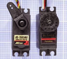
In common electronics applications, values larg­ er than 4,700μF or smaller than 10pF are unusual.

Electrolytics are available at a moderate price in a wider range of values than other commonly used capacitors. They range from 1μF to 4,700μF and sometimes beyond. Working voltages typically range from 6.3VDC to 100VDC, but can be as high as 450VDC.

Tantalum capacitors are usually unavailable in sizes above 150μF or for voltages above 35VDC.

Single-layer ceramic capacitors have small val­ues ranging from 0.01μF to 0.22μF, with working voltages usually not exceeding 50VDC, although very small-value capacitors may be rated much higher for special applications. Poor tolerances of +80% to -20% are common.

Some variants of multi-layer ceramic capacitors are capable of storing up to 47μF, although 10μF is a more common upper limit. They are seldom rated above 100VDC. Some are accurate to plus- or-minus 5%.


Dielectric Constant

If A is the area of each plate in a capacitor (meas­ ured in square centimeters), and T is the thick­ ness of the dielectric (measured in centimeters), and K is the dielectric constant of the capacitor, the capacitance, C (measured in farads) will be obtained from the formula:

C = (0.0885 * K * A) / T

The dielectric constant of air is 1. Other dielectrics have different standard values. Polyethylene, for instance, has a constant of approximately 2.3. Thus a capacitor of 1 square centimeter plate area and polyethylene dielectric 0.01 centime­ ters thick would have a capacitance of about 20pF. A tantalum capacitor of equal plate area and dielectric thickness would have capacitance closer to 100pF, since the dielectric constant of tantalum oxide is much higher than that of poly­ ethylene.

The Time Constant

When a capacitor is charged in series through a resistor (it is used in an RC network), and it begins with no charge on its plates, the time constant is the time, in seconds, required to charge the ca­ pacitor to 63% of the supply voltage. After an additional, identical interval of time, the capaci­ tor will acquire 63% of the remaining difference between itself and the power supply. In theory the capacitor gets closer and closer to a full charge, but never quite reaches 100%. However, five time constants are sufficient for the capacitor to reach 99%, which is regarded as close enough to being fully charged for all practical purposes.

Refer to Figure 12-3 for a schematic of an RC net­ work.

The time constant is a simple function of the re­ sistance and the capacitance. If R is the value of the resistor (in ohms), and C is the value of the capacitor (in farads), the time constant, TC, will be obtained by the formula:

TC = R * C

If we multiply the R value by 1,000 while dividing the C value by 1,000, the time constant remains the same, and we can use the more convenient values of kilohms for the resistance and μF for the capacitance. In other words, the formula tells us that a 1K resistor in series with a 1,000μF capac­itor has a time constant of 1 second.

The formula suggests that if the value of R di­ minishes to zero, the capacitor will charge in­ stantly. In reality, the charging time will be rapid but finite, limited by factors such as the electrical resistance of the materials used.

Multiple Capacitors

When two or more capacitors are wired in parallel, their total capacitance is the sum of their sep­ arate capacitances. When two or more capacitors are wired in series, the relationship between their total capacitance © and their individual capaci­tances (C1, C2, C3 . . .) is given by this formula:

1 / C = (1/C1) + (1/C2) + (1/C3). . .

The formula to calculate the total capacitance of capacitors connected in series resembles the one used to calculate the total resistance of resistors connected in parallel. See Chapter 10.

Alternating Current and Capacitive Reactance

The apparent resistance of a capacitor to AC is properly known as capacitive reactance. In the following formula, capacitive reactance (XC, in ohms) is derived as a function of capacitance (C, in farads) and AC frequency (f, measured in hertz):

XC = 1 / (2 * π * f * C)

The formula shows that when frequency be­ comes zero, capacitive reactance becomes infin­ ite; in other words, a capacitor has theoretically infinite resistance when DC current tries to flow through it. In reality, a dielectric has a finite re­ sistance, and thus always allows some leakage.

The formula also shows that capacitive reactance diminishes when the size of the capacitor increa­

ses and/or the frequency being applied to it in­ creases. From this it appears that an AC signal will be attenuated less at higher frequencies, espe­ cially if we use a small capacitor. However, a real- world capacitor also exhibits some degree of in­ ductive reactance. This value will depend on its configuration (cylindrical vs. multiple flat plates), its physical length, the materials from which it is fabricated, the lengths of its leads, and other fac­ tors. Inductive reactance tends to increase with frequency, and since capacitive reactance tends to decrease with frequency, at some point the curves for the two functions intersect. This point represents the capacitor’s self-resonant frequen­ cy, which is often referred to simply as its resonant frequency. See Figure 12-18.
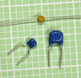
clip_image044

Figure 12-18. As an AC current applied to a capacitor in- creases in frequency, the capacitive reactance of the com- ponent decreases, while its inductive reactance increases. The resonant frequency of the capacitor is found where the two functions intersect.

Equivalent Series Resistance

A theoretically ideal capacitor would be purely reactive, without any resistance. In reality, capac­ itors are not ideal, and they have equivalent series resistance, or ESR. This is defined as the resistor
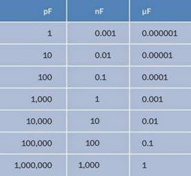
that you would have to place in series with an ideal version of the capacitor, so that the combi­ nation would behave like the real version of the capacitor on its own.

If Xc is the reactance of the capacitor, then its Q factor (which means its quality factor) is given by the simple formula:

Q = Xc / ESR

Thus, the quality factor is higher if the ESR is rel­ atively low. However, the reactance of the capac­ itor will vary significantly with frequency, and this simple formula is only an approximate guide.

The Q-factor for capacitors should not be con­ fused with the Q-factor for inductors, which is calculated quite differently.

How to Use it

The figures illustrate some simplified schematics for common applications.

Bypass Capacitor

In Figure 12-19, a low-value capacitor (often 0.1μF) is placed near the power input pin of a sensitive digital chip to divert high-frequency spikes or noise to negative ground. This bypass capacitor may also be described as a decoupling capacitor.

clip_image046

Figure 12-19. A bypass capacitor (typically 0.1μF) config- ured to protect an integrated circuit logic chip from volt- age spikes and noise in the power supply.


Coupling Capacitor

In Figure 12-20, a 1μF coupling capacitor trans­ mits a pulse from one section of a circuit to an­ other, while blocking the DC voltage. Some re­ shaping of the waveform may occur.

clip_image048

Figure 12-20. A coupling capacitor (typically around 1μF) preserves DC isolation of one section of a circuit from an- other, while allowing a pulse to be transmitted.

High-Pass Filter

In Figure 12-21, a 0.1μF capacitor blocks the low- frequency component of a complex waveform and transmits only the higher frequency that was superimposed on the low frequency.

Low-Pass Filter

In Figure 12-22, a 0.1μF decoupling capacitor di­ verts the higher frequency component of a com­ plex waveform to negative ground, allowing only

clip_image050

clip_image052Figure 12-21. A small capacitor (typically 0.1μF) can be used to create a high-pass filter, passing high frequencies while blocking low frequencies.

the lower frequency to be preserved. A lower- value capacitor (such as 0.001μF) will bleed away high-frequency noise from an AM radio source without affecting audio frequencies.

Smoothing Capacitor

In Figure 12-23, a 100μF capacitor charges and discharges to smooth an AC signal after a diode has removed the negative portion.

Snubber

In Figure 12-24, an RC network (inside a white dashed line) is known as a snubber when used to protect a switch from the problem of arcing (pro­ nounced “arking”)—that is, a sustained spark that can quickly erode the switch contacts. Arc­ ing may occur in switches, pushbuttons, or relays

Figure 12-22. A small capacitor (typically 0.1μF) in this configuration routes high frequencies to negative ground, filtering them out of an analog signal.

that control an inductive load, such as a large motor. This problem can become significant at high DC currents (10A or more) or relatively high AC or DC voltages (100V or more).

When the switch is opened, the magnetic field that has been sustained by the inductive load collapses, causing a surge of current, or forward EMF. The capacitor in the snubber absorbs this surge, thus protecting the switch contacts. When the switch is closed again, the capacitor dis­ charges itself, but the resistor limits the outrush of current—again, protecting the switch.

A snubber placed around the switch in a DC cir­ cuit could typically use a 0.1μF capacitor (poly­ propylene or polyester) rated for 125VAC/ 200VDC, and a 100-ohm carbon resistor rated 0.5

clip_image054

clip_image056Figure 12-23. A capacitor of 100μF or more smooths the upper half of an AC signal that has passed through a di- ode. The capacitor charges during each positive pulse and discharges to “fill the gaps” between them.

watt or higher. Prepackaged snubbers contain­ ing appropriate capacitor-resistor pairs are avail­ able from some parts suppliers, primarily for in­ dustrial use.

In an AC circuit, a snubber can be placed around the inductive load itself. Although a diode is often used this way in a DC circuit, it cannot be used with AC.

Although solid-state switching devices such as a solid state relay contain no mechanical con­ tacts, they may still be damaged by substantial pulses of back-EMF, and can be protected by a snubber where they are controlling inductive loads that take 10A or more at 100V or more.

Figure 12-24. An RC network (outlined with a white dash- ed line) protects a switch that controls a high inductive load. Used in this way, the RC network is known as a snub- ber.

Capacitor as a Battery Substitute

A capacitor may be substituted for a battery for some applications, although it has a lower ener­ gy density and will be more expensive to manu­ facture. A capacitor charges and discharges much more rapidly than a battery because no chemical reactions are involved, but a battery sustains its voltage much more successfully dur­ ing the discharge cycle.

Capacitors that can store a very large amount of energy are often referred to as supercapacitors.

What Can Go Wrong

Common problems associated with capacitors are age-related deterioration (especially in elec­ trolytics), inductive reactance (especially in cy­ lindrical formats), nonlinear response, resistivity, excessive current leakage, and dielectric memo­ ry. Some of these problems are discussed below. A manufacturer’s datasheet should be consulted

carefully in conjunction with the notes regarding compositions in the preceding Variants section before making a commitment to a particular type of capacitor.

Wrong Polarity

A polarized capacitor may offer virtually no re­ sistance if it is connected the wrong way around to a DC power source. A very high current can result, damaging the capacitor and probably other components in the circuit. Failing to ob­ serve the polarity of a tantalum capacitor can have destructive or even explosive conse­ quences, depending on the amperage.

Voltage Overload

If the DC working voltage of a capacitor is excee­ ded, there is a risk of breaking down the dielectric and allowing a spark, or arc, that will form a short circuit. Note that the DC rating of a capacitor does not mean that it can be used safely with an equivalent AC voltage. The maximum AC voltage should be no greater than approximately 0.7 times the DC rated voltage. If a DC-rated capac­ itor is used directly across an AC power line, it will create an effective short circuit.

If capacitors are connected in series or in parallel, ideally the voltage rating for each capacitor should be the same, and certainly no less than the supply voltage.

Tantalum capacitors are easily damaged by cur­ rent spikes that exceed their maximum working voltage, and are unsuitable for high-frequency coupling because of their inductance.

Leakage

Charge leakage is a problem especially associ­ ated with electrolytic capacitors, which are not suitable for storing a charge over a significant in­ terval. Polypropalene or polystyrene film capac­ itors are a better choice.

Dielectric Memory

Also known as dielectric absorption, this is a phe­ nomenon in which a capacitor’s electrolyte dis­

plays some percentage of its former voltage after the capacitor has been discharged and then dis­ connected from the circuit. Single-layer ceramic capacitors especially tend to suffer from this problem.

Specific Electrolytic Issues Electrolytic capacitors have high inductive reac­ tance, are not manufactured to close tolerances, and deteriorate significantly with age. While oth­

er components may be stockpiled and used over

a period of years, this is not a sensible policy with electrolytics.

The “capacitor plague” affecting many of these capacitors manufactured from 1999 onward pro­ vided a salutary lesson regarding their potential weaknesses. Faulty composition of the dielectric allowed it to deteriorate, liberating hydrogen gas, which eventually caused the aluminum shells of the capacitors to bulge and burst. Circuit boards from major manufacturers were affected. Because the problem took two years to become apparent, literally millions of boards with faulty capacitors had been sold before the fault was di­ agnosed and eventually corrected.

Unfortunately electrolytics cannot be easily re­ placed with other types of capacitors in applica­ tions such as power supplies, because substi­ tutes will be considerably larger and more ex­ pensive.

Heat

The equivalent series resistance (ESR) of a large capacitor inevitably means that it must dissipate some power as heat during use. Ripple current can also create heat. Capacitor performance will change as the temperature increases. A common maximum component temperature for electro­ lytic capacitors is 85 degrees Centigrade.

Vibration

In a high-vibration environment, electrolytics should be protected by clamping them mechan­ ically in place, using a capacitor clamp, also known as a c-clamp.

clip_image009[6]110 Encyclopedia of Electronic Components Volume 1

power > moderation > capacitor What Can Go Wrong

Misleading Nomenclature

Rarely, in the United States, the term “mF” may be used as a probable alternative to μF. This can be a source of confusion and risk because mF is properly (but very rarely) used to mean “millifar­ ads.” The term should always be avoided.


DC-DC converter What It Does,How It Works,Variants,Values,How to Use it,What Can Go Wrong

Often referred to as a switching regulator, and sometimes as a switcher, not to be confused with a switching power supply.

What It Does

A DC-DC converter, often referred to simply as a converter, receives a DC voltage as its input and converts it to a regulated DC voltage as its out­ put. The output voltage may be higher or lower than the input voltage, may be user-adjustable by adding an external resistor, and may be com­pletely electrically isolated from the input, de­ pending on the type of converter that is used.

There is no single symbol to represent a DC-DC converter. Some simplified schematics showing the principles of operation of commonly used converters are referenced under the following Variants section.

A DC-DC converter is also typically found in the output stage of a switching AC-DC power sup­ ply.


The overall efficiency is not greatly affected by

the difference between input and output volt­ age, and can exceed 90%, minimizing waste heat and enabling the unit to be extremely compact.

A DC-DC converter is an integrated circuit pack­ age that includes a high-speed switching device (almost always, a MOSFET) in conjunction with an oscillator circuit, an inductor, and a diode. By comparison, a linear regulator is usually based around bipolar transistors. Its input must always be at a higher voltage than its output, and its ef­ficiency will be inversely proportional with the voltage drop that it imposes. See the voltage regulator entry in this encyclopedia for addi­tional information.

How It Works

An internal oscillator controls a MOSFET semi­ conductor that switches the DC input on and off at a high frequency, usually from 50KHz to 1MHz. Output voltage is adjusted by varying the duty cycle of the oscillator—the length of each “on” pulse relative to each “off” interval. This is known as pulse-width modulation, or PWM. The duty cy­cle is controlled by sampling the output of the converter and using a comparator to subtract the output voltage from a reference voltage, to es­tablish an error value. This is passed to another comparator, which subtracts the error voltage from an oscillator ramp signal. If the error increa­ses, the oscillator signal is more heavily clipped, thus changing the effective ratio of on/off pulse

lengths. A simplified schematic of the PWM cir­cuit is shown in Figure 17-1, which omits other components for clarity. The system of subtract­ing an error voltage from a ramp oscillator volt­ age to obtain a pulse-width modulated signal is illustrated in Figure 17-2.

clip_image005

Figure 17-1. The heart of a DC-DC converter is a MOSFET switch, which operates at a high frequency with pulse-width modulation used to create an adjustable DC output.

clip_image008

Figure 17-2. To achieve pulse-width modulation, an error- level voltage is established by comparing the output from the converter with a reference voltage. The error level, shown as an orange line, is then subtracted from the out- put from a ramp oscillator. The pulse width varies accordingly.

The key to the efficiency of a DC-DC converter is an inductor, which stores energy in its magnetic field during “on” pulse and releases it in the dis­ charge phase. Thus, the inductor is used as a temporary reservoir and minimizes the ripple current. All converter variants use a coil for this purpose, although its placement varies in rela­tion to the diode and capacitor that complete the basic circuit.

Variants

Four basic switching circuits are used in DC-DC converters and are defined in the coming sec­tions, with a formula to determine the ratio be­ tween input voltage (Vin) and output voltage (Vout) in each case. In these formulae, variable D is the duty cycle in the pulse train generated through an internal MOSFET switch. The duty cy­cle is the fraction of the total on-off cycle that is occupied by each “on” pulse. In other words, if


Ton is the duration of an “on” pulse and Toff is the “off” time:

0= Ton / (Ton + Toff)

Buck Converter

See Figure 17-3. The output voltage is lower than the input voltage. The input and output share a common ground. For this circuit:

Vout = Vin * D

clip_image010

Figure 17-3. Basic topology of a buck-type DC-DC converter.

Boost Converter

See Figure 17-4. The output voltage is greater than the input voltage. The input and output share a common ground. For this circuit:

Vout = Vin / (1-D)

clip_image013

Figure 17-4. Basic topology of a boost-type DC-DC converter.

Flyback Converter with Inductor

Commonly known as a buck-boost converter. See Figure 17-5. The output voltage can be less than or greater than the input voltage. The input and

output share a common ground. For this circuit:

Vout = Vin * (D / (1-D))

clip_image015

Figure 17-5. Basic topology of a fly back type DC-DC converter.


Fly back Converter with Transformer

See Figure 17-6. The output voltage can be less than or greater than the input voltage. The input and output are isolated from one another. For this circuit:

Vout = Vin * (D / (1-D))

clip_image017

Figure 17-6. Basic topology of a fly back type DC-DC con- verter. (Buck, boost, and fly back topologies adapted from Maxim Integrated Products.)

Using a transformer in the converter allows mul­tiple outputs with different voltages, supplied through multiple transformer windings.

Formats

A converter may be packaged in a flat rectangu­lar box that requires no additional heat sink and has pins for through-hole insertion into a PC board. Sizes usually range up to to 2” × 2”. Power handling can range from 5 to 30 watts. Convert­ers of this type are shown in Figure 17-7. (Top: Input range of 9 to 18VDC, fixed output of 5VDC at 3A completely isolated from the input. Typical efficiency of approximately 80%. The case is made of copper, providing good heat dissipation with electrical shielding. Center: Input range of 9 to 18VDC, fixed output of 5VDC at 500mA com­pletely isolated from the input. Typical efficiency of approximately 75%. The manufacturer claims that external capacitors are only needed in criti­cal applications. Bottom: SIP format, fixed input

of 12VDC, fixed output of 5VDC at 600mA com­pletely isolated from the input. Typical efficiency of approximately 75%. Requires external capac­itors for ripple rejection.)

clip_image020

Figure 17-7. A selection of sealed DC-DC converters.

Lower-power converters are also available as surface-mount devices.

Some adjustable-output converters are supplied as multiple surface-mounted components pre­ installed on a mini-board that has pins for through-hole insertion in a printed circuit board. Their high efficiency enables them to handle a lot of power for their size. In Figure 17-8, the con­verter accepts a 4.5 to 14VDC input range and has an adjustable output of 0.6 to 6VDC. It is rated at a surprising 10A or 50W and is more than 90% efficient. However, it draws 80mA in a no-load state, causing it to become quite hot. A thermal cutout or automatic shutdown may be used if the converter will not be driving a consistent load.


clip_image022

Figure 17-8. An adjustable DC-DC converter rated for 10A or 50W. The output voltage is determined by adding an external resistor or trimmer potentiometer. External smoothing capacitors are required, as shown in the component’s datasheet.

The miniboard in Figure 17-9 accepts an input voltage from 7 to 36VDC and has an adjustable output ranging from 2.5 to 12.6VDC, at up to 6A. It is non-isolated (has a common negative bus) and claims to be more than 95% efficient at full load.

The miniboard in Figure 17-10 accepts an input voltage from 4.5 to 14VDC and has an adjustable output ranging from 0.6 to 6VDC at up to 20A. It is non-isolated (has a common negative bus) and claims to be more than 90% efficient at full load.

Values

Relevant values include:

Nominal Input Voltage and Frequency

A wide range of input voltages is often accepta­ble, as the PWM can vary accordingly. Converters

clip_image024

Figure 17-9. Another adjustable DC-DC converter. The output voltage is determined by adding an external resistor or trimmer potentiometer. External smoothing capaci- tors are required, as shown in the component’s datasheet.

clip_image026

Figure 17-10. Another adjustable DC-DC converter. The output voltage is determined by adding an external resistor or trimmer potentiometer. External smoothing capaci- tors are required, as shown in the component’s datasheet.

often allow equipment to be usable internation­ ally, on any voltage ranging from 100VAC to 250VAC, at a fequency of 50Hz or 60Hz, without any adaptation.

Output Voltage

As previously noted, many converters allow the output voltage to be adjusted by adding an ex­ternal resistor or potentiometer. Alternatively, there may be multiple fixed output voltages, ac­ cessible via different pins on the package. They may also provide a positive voltage and equally opposite negative voltage relative to a ground pin.

Input Current and Output Current Because input voltage and output voltage are likely to be different, the current alone is not a reliable guide to power handling.

A datasheet should specify input current with no load (open circuit on the output side). This cur­ rent will have to be entirely dissipated as heat.

Load Regulation

This is usually expressed as a percentage and suggests the extent to which output voltage may be pulled down when the load on a DC-DC con­verter increases. If Vnil is the measured output voltage with no load, and Vmax is the measured output voltage with the maximum rated load:

Load regulation = 100 * (Vnil – Vmax)/Vmax

However, note that some converters are de­ signed with the expectation that they will never be used with zero load across the output. In these cases, Vnil will be the voltage at minimum rated load.

Efficiency

This is a measure of how much input current must be dissipated as heat. A converter with a 12-volt input, drawing a maximum 300mA input current, will consume 3.6 watts (3,600mW). If it is 80% efficient, it will have to dissipate roughly 20% of its power as heat, or 720mW.

Ripple and Noise

Sometimes abbreviated R/N, this may be meas­ured in mV or as a percentage. Check the speci­fication carefully to determine whether the ripple-and-noise values require use of external smoothing capacitors. Often, this is the case.

Isolated or Non-Isolated

This crucial piece of information is often found near the top of a datasheet, not in the detailed specifications.

How to Use it

Because a converter creates electrical noise, it should be prevented from affecting other com­ ponents by adding substantial bypass capaci­tors as close as possible to its input and output pins. For most converters, external capacitors are mandatory, and their effective series resistance (ESR) should be as low as possible (see the ca­pacitor entry in this encyclopedia for an explan­ation of ESR). Tantalum capacitors are preferable to electrolytics for this reason, and are also more durable. Some manufacturers recommend plac­ing a tantalum capacitor in parallel with an elec­trolytic. A small ceramic capacitor, typically 0.1μF, is often recommended in an addition to larger- value capacitors on the output side.

The voltage rating of each capacitor should be twice the voltage at the point in the circuit where it is used. The capacitance value will usually be higher for higher-current converters. Values of 100μF are common, but for high amperage, a value may be as high as 1,000μF.

While datasheets are often inadequate for some types of components, datasheets for DC-DC converters usually include detailed instructions regarding bypass capacitors. Following these in­ structions is essential. In the relatively rare in­ stances that a datasheet makes no mention of bypass capacitors for a converter, this does not necessarily mean that the capacitors are unnec­ essary. The manufacturer may assume that they will be used as a matter of course.

Converters are used in a very wide range of de­ vices, supplying power ranging from a few milli­ amps to tens of amps. At the lower end of the scale, devices such as cellular telephones, portable computers, and tablets contain sub- circuits that require different voltages, some of which may be higher than the voltage of a single battery or battery pack that powers the device. A converter can satisfy this requirement. Because a converter can be designed to maintain a fixed output in response to a range of input voltages, it can also compensate for the gradual decline in voltage that occurs during battery usage.

A boost-type converter can be used to double the voltage from a single 1.5V battery in an LED flashlight where 3 volts are required to power the LED. Similarly, a boost-type converter can pro­ vide the necessary voltage to run a cold-cathode fluorescent tube that provides backlighting in an LCD computer display.

On a circuit board that is primarily populated with 5VDC components and is fed by a single 5VDC power supply, a converter can be used to supply 12VDC for one special purpose, such as an analog-digital converter or a serial data con­nection.

If electromechanical relays or other inductive loads share a common ground with compo­nents ,such as logic chips or microcontrollers, it may be difficult to protect the sensitive compo­ nents from voltage spikes. A A fly back converter with a transformer separating the output from the input can allow the “noisy” section of the cir­cuit to be segregated, so long as the converter itself does not introduce noise. Since the elec­tromagnetic interference (EMI) introduced by converters varies widely from one model to an­ other, specifications should be checked carefully.

Very low-power components can pick up EMI from the wires or traces leading into and out of a converter. In this type of circuit, adequate noise suppression may be impossible, and a converter may not be appropriate.

What Can Go Wrong

Electrical Noise in Output

Electrolytic capacitors may be inadequate to smooth the high frequencies used. Multilayer ce­ramic capacitors or tantalum capacitors may be necessary. Check the manufacturer’s datasheet for minimum and maximum values. Also check the datasheet for advice regarding placement of capacitors on the input side as well as across the output.

Excess Heat with No Load

Some converters generate substantial heat while they are powered without a load. The manufac­turer’s datasheet may not discuss this potential problem very prominently or in any detail. Check the input rating, usually expressed in mA, speci­ fied for a no-load condition. All of this current will

have to be dissipated as heat, and the very small size of many converters can result in high local­ized temperatures, especially since many of them allow no provision for a heat sink.

Inaccurate Voltage Output with Low Load

Some converters are designed to operate with at least 10% of full rated load across their output at all times. Below this threshold, output voltage can be grossly inaccurate. Read datasheets care­ fully for statements such as this: “Lower than 10% loading will result in an increase in output volt­ age, which may rise to typically double the speci­fied output voltage if the output load falls to less than 5%.” Always use a meter to verify the output voltage from a converter at a variety of different loads, and perform this test before installing the converter in a circuit.