Recurrent Neural Networks , Hopfield Network , Autoassociative Memory , Bidirectional Associative Memories (BAM) , Fuzzy Systems , Fuzzification , Rule Evaluation and Defuzzification .

Recurrent Neural Networks

In contrast to feed forward neural networks, with recurrent networks neuron outputs can be connected with their inputs. Thus, signals in the network can continuously circulate. Until recently, only a limited number of recurrent neural networks were described.

Hopfield Network

The single-layer recurrent network was analyzed by Hopfield (1982). This network, shown in Fig. 19.29, has unipolar hard threshold neurons with outputs equal to 0 or 1. Weights are given by a symmetrical square matrix W with zero elements (wij = 0 for i = j ) on the main diagonal. The stability of the system is usually analyzed by means of the energy function

image

It has been proved that during signal circulation the energy E of the network decreases and the system converges to the stable points. This is especially true when the values of system outputs are updated in the asynchronous mode. This means that at a given cycle, only one random output can be changed to the required values. Hopfield also proved that those stable points which the system converges can be programmed by adjusting the weights using a modified Hebbian rule,

image

Such memory has limited storage capacity. Based on experiments, Hopfield estimated that the maximum number of stored patterns is 0.15N, where N is the number of neurons.

Later the concept of energy function was extended by Hopfield (1984) to one-layer recurrent networks having neurons with continuous activation functions. These types of networks were used to solve many optimization and linear programming problems.

Autoassociative Memory

Hopfield (1984) extended the concept of his network to autoassociative memories. In the same network structure as shown in Fig. 19.29, the bipolar hard-threshold neurons were used with outputs equal to −1

image

or +1. In this network, pattern s m are stored into the weight matrix W using the autocorrelation algorithm

image

where M is the number of stored pattern and I is the unity matrix. Note that W is the square symmetrical matrix with elements on the main diagonal equal to zero (w ji for i = j ). Using a modified formula (19.42), new patterns can be added or subtracted from memory. When such memory is exposed to a binary bipolar pattern by enforcing the initial network states, after signal circulation the network will converge to the closest (most similar) stored pattern or to its complement. This stable point will be at the closest minimum of the energy

image

Like the Hopfield network, the autoassociative memory has limited storage capacity, which is estimated to be about Mmax = 0.15N. When the number of stored patterns is large and close to the memory capacity, the network has a tendency to converge to spurious states, which were not stored. These spurious states are additional minima of the energy function.

Bidirectional Associative Memories (BAM)

The concept of the autoassociative memory was extended to bidirectional associative memories (BAM) by Kosko (1987, 1988). This memory, shown in Fig. 19.30, is able to associate pairs of the patterns a and b. This is the two-layer network with the output of the second layer connected directly to the input of the first layer. The weight matrix of the second layer is WT and W for the first layer. The rectangular weight matrix W is obtained as a sum of the cross-correlation matrixes

image

where M is the number of stored pairs, and am and bm are the stored vector pairs. If the nodes a or b are initialized with a vector similar to the stored one, then after signal circulations, both stored patterns am and bm should be recovered. The BAM has limited memory capacity and memory corruption problems similar to the autoassociative memory. The BAM concept can be extended for association of three or more vectors.

image

Fuzzy Systems

The main applications of neural networks are re- lated to the nonlinear mapping of n-dimensional input variables into m-dimensional output variables.

Such a function is often required in control systems, where for specific measured variables certain control variables must be generated. Another approach for nonlinear mapping of one set of variables into another set of variables is the fuzzy controller. The principle of operation of the fuzzy controller significantly differs from neural networks. The block diagram of a fuzzy controller is shown in Fig. 19.31.

image

In the first step, analog inputs are converted into a set of fuzzy variables. In this step, for each analog input, 3–9 fuzzy variables typically are generated. Each fuzzy variable has an analog value between zero and one. In the next step, a fuzzy logic is applied to the input fuzzy variables and a resulting set of output variables is generated. In the last step, known as defuzzification, from a set of output fuzzy variables, one or more output analog variables are generated, which are used as control variables.

Fuzzification

The purpose of fuzzification is to convert an analog variable input into a set of fuzzy variables. For higher accuracy, more fuzzy variables will be chosen. To illustrate the fuzzification process, consider that the input variable is the temperature and is coded into five fuzzy variables: cold, cool, normal, warm, and hot. Each fuzzy variable should obtain a value between zero and one, which describes a degree of association of the analog input (temperature) within the given fuzzy variable. Sometimes, instead of the term degree of association, the term degree of membership is used. The process of fuzzification is illustrated in Fig. 19.32. Using Fig. 19.32 we can find the degree of association of each fuzzy variable with the given temperature.

For example, for a temperature of 57◦F, the following set of fuzzy variables is obtained: (0, 0.5, 0.2, 0, 0), and for T = 80◦F it is (0, 0, 0.25, 0.7, 0). Usually only one or two fuzzy variables have a value other than zero. In the example, trapezoidal functions are used for calculation of the degree of association. Various different functions such as triangular or Gaussian, can also be used, as long as the computed value is in the range from zero to one. Each membership function is described by only three or four parameters, which have to be stored in memory.

For proper design of the fuzzification stage, certain practical rules should be used:

✁ Each point of the input analog variable should belong to at least one and no more than two membership functions.

✁ For overlapping functions, the sum of two membership functions must not be larger than one. This also means that overlaps must not cross the points of maximum values (ones).

✁ For higher accuracy, more membership functions should be used. However, very dense functions lead to frequent system reaction and sometimes to system instability.

image

Rule Evaluation

Contrary to Boolean logic where variables can have only binary states, in fuzzy logic all variables may have any values between zero and one. The fuzzy logic consists of the same basic ∧ – AND, ∨-OR, and NOT operators

image

For example 0.1 ∧ 0.7 ∧ 0.3 = 0.1, 0.1 ∨ 0.7 ∨ 0.3 = 0.7, and 0¯.3 = 0.7. These rules are also known as Zadeh AND, OR, and NOT operators (Zadeh, 1965). Note that these rules are true also for classical binary logic.

Fuzzy rules are specified in the fuzzy table as it is shown for a given system. Consider a simple system with two analog input variables x and y, and one output variable z. The goal is to design a fuzzy sys- tem generating z as f (x, y). After fuzzification, the analog variable x is represented by five fuzzy variables: x1, x2, x3, x4, x5 and an analog variable y is represented by three fuzzy variables: y1, y2, y3. Assume that an analog output variable is represented by four fuzzy variables: z1, z2, z3, z4. The key issue of the design process is to set proper output fuzzy variables zk for all combinations of input fuzzy variables, as is shown in the table in Fig. 19.33. The designer has to specify many rules such as if inputs are represented by fuzzy variables xi and y j , then the output should be represented by fuzzy variable zk . Once the fuzzy table is specified, the fuzzy logic computation proceeds in two steps. First each field of the fuzzy table is filled with intermediate fuzzy variables tij , obtained from AND operator tij = min{xi , y j }, as shown in Fig. 19.33(b). This step is independent of the required rules for a given system. In the second step, the OR (max) operator is used to compute each output fuzzy variable zk . In the given example in Fig. 19.33, z1 = max{t11, t12, t21, t41, t51}, z2 = max{t13, t31, t42, t52}, z3 = max{t22, t23, t43}, z4 = max{t32, t34, t53}. Note that the formulas depend on the specifications given in the fuzzy table shown in Fig. 19.33(a).

Defuzzification

As a result of fuzzy rule evaluation, each analog output variable is represented by several fuzzy variables. The purpose of defuzzification is to obtain analog outputs. This can be done by using a membership function similar to that shown in Fig. 19.32. In the first step, fuzzy variables obtained from rule evaluations are used to modify the membership function employing the formula

image

For example, if the output fuzzy variables are: 0, 0.2, 0.7, 0.0, then the modified membership functions have shapes shown by the thick line in Fig. 19.34. The analog value of the z variable is found as a center of gravity of modified membership functions µ∗(z),

image

image

In the case where shapes of the output membership functions µk (z) are the same, the equation can be simplified to

image

Equation (19.47) is usually too complicated to be used in a simple microcontroller based system; therefore, in practical cases, Eq. (19.48) is used more frequently.


Learning Algorithms for Neural Networks : Hebbian Learning Rule , Correlation Learning Rule , Instar Learning Rule , Winner Takes All (WTA) , Out star Learning Rule , Widrow-Hoff LMS Learning Rule , Linear Regression , Delta Learning Rule , Error Backpropagation Learning , Special Feed forward Networks , Functional Link Network , Feed forward Version of the Counterpropagation Network and Cascade Correlation Architecture .

Learning Algorithms for Neural Networks

Similarly to the biological neurons, the weights in artificial neurons are adjusted during a training procedure. Various learning algorithms were developed, and only a few are suitable for multilayer neuron networks. Some use only local signals in the neurons, others require information from outputs; some require a supervisor who knows what outputs should be for the given patterns, and other unsupervised algorithms need no such information. Common learning rules are described in the following sections.

Hebbian Learning Rule

The Hebb (1949) learning rule is based on the assumption that if two neighbor neurons must be activated and deactivated at the same time, then the weight connecting these neurons should increase. For neurons operating in the opposite phase, the weight between them should decrease. If there is no signal correlation, the weight should remain unchanged. This assumption can be described by the formula

image

The training process starts usually with values of all weights set to zero. This learning rule can be used for both soft and hard threshold neurons. Since desired responses of neurons is not used in the learning procedure, this is the unsupervised learning rule. The absolute values of the weights are usually proportional to the learning time, which is undesired.

Correlation Learning Rule

The correlation learning rule is based on a similar principle as the Hebbian learning rule. It assumes that weights between simultaneously responding neurons should be largely positive, and weights between neurons with opposite reaction should be largely negative.

Contrary to the Hebbian rule, the correlation rule is the supervised learning. Instead of actual response o j , the desired response d j is used for the weight change calculation

image

This training algorithm usually starts with initialization of weights to zero values.

Instar Learning Rule

If input vectors and weights are normalized, or they have only binary bipolar values (−1 or +1), then the net value will have the largest positive value when the weights and the input signals are the same. Therefore, weights should be changed only if they are different from the signals

image

Note, that the information required for the weight is taken only from the input signals. This is a very local and unsupervised learning algorithm.

Winner Takes All (WTA)

The WTA is a modification of the instar algorithm where weights are modified only for the neuron with the highest net value. Weights of remaining neurons are left unchanged. Sometimes this algorithm is modified in such a way that a few neurons with the highest net values are modified at the same time. Although this is an unsupervised algorithm because we do not know what are desired outputs, there is a need for “judge” or “supervisor” to find a winner with a largest net value. The WTA algorithm, developed by Kohonen (1982), is often used for automatic clustering and for extracting statistical properties of input data.

Outstar Learning Rule

In the outstar learning rule, it is required that weights connected to a certain node should be equal to the desired outputs for the neurons connected through those weights

image

where d j is the desired neuron output and c is small learning constant, which further decreases during the learning procedure. This is the supervised training procedure because desired outputs must be known. Both instar and outstar learning rules were developed by Grossberg (1969).

Widrow-Hoff LMS Learning Rule

Widrow and Hoff (1960, 1962) developed a supervised training algorithm which allows training a neuron for the desired response. This rule was derived so that the square of the difference between the net and output value is minimized.

image

Note that weight change Υwij is a sum of the changes from each of the individual applied patterns. Therefore, it is possible to correct the weight after each individual pattern was applied. This process is known as incremental updating; cumulative updating is when weights are changed after all patterns have been applied. Incremental updating usually leads to a solution faster, but it is sensitive to the order in which patterns are applied. If the learning constant c is chosen to be small, then both methods give the same result. The LMS rule works well for all types of activation functions. This rule tries to enforce the net value to be equal to desired value. Sometimes this is not what the observer is looking for. It is usually not important what the net value is, but it is important if the net value is positive or negative. For example, a very large net value with a proper sign will result in correct output and in large error as defined by Eq. (19.13) and this may be the preferred solution.

Linear Regression

The LMS learning rule requires hundreds or thousands of iterations, using formula (19.14), before it converges to the proper solution. Using the linear regression rule, the same result can be obtained in only one step.

Considering one neuron and using vector notation for a set of the input patterns X applied through weight vector w, the vector of net values net is calculated using

image

Note that the size of the input patterns is always augmented by one, and this additional weight is responsible for the threshold (see Fig. 19.3(b)). This method, similar to the LMS rule, assumes a linear activation function, and so the net values net should be equal to desired output values d

image

Usually p > n + 1, and the preceding equation can be solved only in the least mean square error sense.

Using the vector arithmetic, the solution is given by

image

When traditional method is used the set of p equations with n + 1 unknowns Eq. (19.16) has to be converted to the set of n + 1 equations with n + 1 unknowns

image

Delta Learning Rule

The LMS method assumes linear activation function net = o, and the obtained solution is sometimes far from optimum, as is shown in Fig. 19.20 for a simple two-dimensional case, with four patterns belonging to two categories. In the solution obtained using the LMS algorithm, one pattern is misclassified. If error is defined as

image

since o = f (net) and the net is given by Eq. (19.2). Note that this derivative is proportional to the derivative of the activation function f t(net). Thus, this type of approach is possible only for continuous activation

image

FIGURE 19.20 An example with a comparison of results obtained using LMS and delta training algorithms. Note that LMS is not able to find the proper solution.

functions and this method cannot be used with hard activation functions (19.4) and (19.5). In this respect the LMS method is more general. The derivatives most common continuous activation functions are

image

the weight change should be proportional to input signal xi , to the difference between desired and actual outputs d jp o jp , and to the derivative of the activation function f t . Similar to the LMS rule, weights can be updated in both the incremental and the cumulative methods. In comparison to the LMS rule, the delta rule always leads to a solution close to the optimum. As it is illustrated in Fig. 19.20, when the delta rule is used, all four patterns are classified correctly.

Error Backpropagation Learning

The delta learning rule can be generalized for multilayer networks. Using an approach similiar to the delta rule, the gradient of the global error can be computed with respect to each weight in the network. Interestingly,

image

image

where K is the number of network outputs A jk is the small signal gain from the input of j th neuron to the kth network output, as Fig. 19.21 shows. The calculation of the backpropagating error starts at the output layer and cumulative errors are calculated layer by layer to the input layer. This approach is not practical from the point of view of hardware realization. Instead, it is simpler to find signal gains from the input of the j th neuron to each of the network outputs (Fig. 19.21). In this case, weights are corrected using

image

Note that this formula is general, regardless of if neurons are arranged in layers or not. One way to find gains Ajk is to introduce an incremental change on the input of the j th neuron and observe the change in the kth network output. This procedure requires only forward signal propagation, and it is easy to implement in a hardware realization. Another possible way is to calculate gains through each layer and then find the total gains as products of layer gains. This procedure is equally or less computationally intensive than a calculation of cumulative errors in the error backpropagation algorithm.

The backpropagation algorithm has a tendency for oscillation. To smooth the process, the weights increment Υwij can be modified according to Rumelhart, Hinton, and Wiliams (1986)

image

where α is the momentum term.

The backpropagation algorithm can be significantly sped up, when, after finding components of the gradient, weights are modified along the gradient direction until a minimum is reached. This process can be carried on without the necessity of a computationally intensive gradient calculation at each step. The new gradient components are calculated once a minimum is obtained in the direction of the previous gradient.

image

This process is only possible for cumulative weight adjustment. One method of finding a minimum along the gradient direction is the tree step process of finding error for three points along gradient direction and then, using a parabola approximation, jump directly to the minimum. The fast learning algorithm using the described approach was proposed by Fahlman (1988) and is known as the quickprop.

The backpropagation algorithm has many disadvantages, which lead to very slow convergency. One of the most painful is that in the backpropagation algorithm, the learning process almost perishes for neurons responding with the maximally wrong answer. For example, if the value on the neuron output is close to +1 and desired output should be close to −1, then the neuron gain f t(net) ≈ 0 and the error signal cannot backpropagate, and so the learning procedure is not effective. To overcome this difficulty, a modified method for derivative calculation was introduced by Wilamowski and Torvik (1993). The derivative is calculated as the slope of a line connecting the point of the output value with the point of the desired value, as shown in Fig. 19.22.

image

Note that for small errors, Eq. (19.31) converges to the derivative of activation function at the point of the output value. With an increase of system dimensionality, the chances for local minima decrease. It is believed that the described phenomenon, rather than a trapping in local minima, is responsible for convergency problems in the error backpropagation algorithm.

Special Feedforward Networks

The multilayer backpropagation network, as shown in Fig. 19.17, is a commonly used feedforward network. This network consists of neurons with the sigmoid type continuous activation function presented in Fig. 19.16(c) and Fig. 19.16(d). In most cases, only one hidden layer is required, and the number of neurons in the hidden layer are chosen to be proportional to the problem complexity. The number of neurons in the hidden layer is usually found by a trial-and-error process. The training process starts with all weights randomized to small values, and the error backpropagation algorithm is used to find a solution. When the learning process does not converge, the training is repeated with a new set of randomly chosen weights. Nguyen and Widrow (1990) proposed an experimental approach for the two-layer network weight initialization. In the second layer, weights are randomly chosen in the range from −0.5 to +0.5. In the first layer, initial weights are calculated from

image

where zij is the random number from −0.5 to +0.5 and the scaling factor β is given by

image

where n is the number of inputs and N is the number of hidden neurons in the first layer. This type of weight initialization usually leads to faster solutions.

For adequate solutions with backpropagation networks, typically many tries are required with different network structures and different initial random weights. It is important that the trained network gains a generalization property. This means that the trained network also should be able to handle correctly patterns that were not used for training. Therefore, in the training procedure, often some data are removed from the training patterns and then these patterns are used for verification. The results with backpropagation networks often depend on luck. This encouraged researchers to develop feedforward networks, which can be more reliable. Some of those networks are described in the following sections.

Functional Link Network

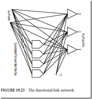
One-layer neural networks are relatively easy to train, but these networks can solve only linearly separated problems. One possible solution for nonlinear problems presented by Nilsson (1965) and elaborated by Pao (1989) using the functional link net- work is shown in Fig. 19.23. Using nonlinear terms with initially determined functions, the actual number of inputs supplied to the one-layer neural net- work is increased. In the simplest case, nonlinear elements are higher order terms of input patterns. Note that the functional link network can be treated as a one-layer network, where additional input data are generated off line using nonlinear transformations. The learning procedure for one-layer is easy and fast. Figure 19.24 shows an XOR problem solved using functional link networks. Note that when the functional link approach is used, this difficult problem becomes a trivial one. The problem with the functional link network is that proper selection of nonlinear elements is not an easy task. In many practical cases, however, it is not difficult to predict what kind of transformation of input data may linearize the problem, and so the functional link approach can be used.

image

image

image

Feedforward Version of the Counterpropagation Network

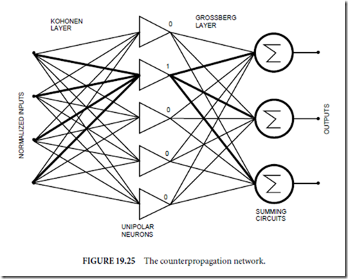
The counterpropagation network was originally proposed by Hecht-Nilsen (1987). In this section a modified feedforward version as described by Zurada (1992) is discussed. This network, which is shown in Fig. 19.25, requires numbers of hidden neurons equal to the number of input patterns, or more exactly, to the number of input clusters. The first layer is known as the Kohonen layer with unipolar neurons. In this layer only one neuron, the winner, can be active. The second is the Grossberg outstar layer. The Kohonen layer can be trained in the unsupervised mode, but that need not be the case. When binary input patterns are considered, then the input weights must be exactly equal to the input patterns. In this case,

image

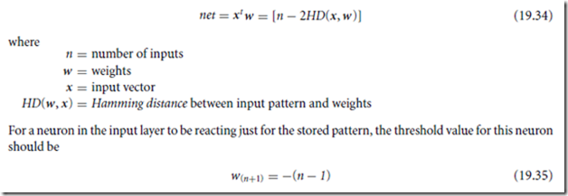
If it is required that the neuron must also react for similar patterns, then the threshold should be set to wn+1 = −[n − (1 + HD)], where HD is the Hamming distance defining the range of similarity. Since for a given input pattern only one neuron in the first layer may have the value of 1 and remaining neurons have 0 values, the weights in the output layer are equal to the required output pattern.

The network, with unipolar activation functions in the first layer, works as a lookup table. When the linear activation function (or no activation function at all) is used in the second layer, then the network also can be considered as an analog memory. For the address applied to the input as a binary vector, the stored set of analog values, as weights in the second layer, can be accurately recovered. The feedforward counterpropagation network may also use analog inputs, but in this case all input data should be normalized.

image

The counterpropagation network is very easy to design. The number of neurons in the hidden layer is equal to the number of patterns (clusters). The weights in the input layer are equal to the input patterns, and the weights in the output layer are equal to the output patterns. This simple network can be used for rapid prototyping. The counterpropagation network usually has more hidden neurons than required. However, such an excessive number of hidden neurons are also used in more sophisticated feedforward networks such as the probabilistic neural network (PNN) Specht (1990) or the general regression neural networks (GRNN) Specht (1992).

WTA Architecture

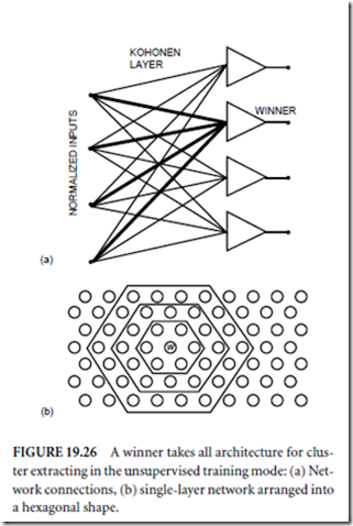
The winner takes all network was proposed by Kohonen (1988). This is basically a one-layer network used in the unsupervised training algorithm to extract a statistical property of the input data (Fig. 19.26(a)). At the first step, all input data are normalized so that the length of each input vector is the same and, usually, equal to unity (Eq. (19.36)). The activation functions of neurons are unipolar and continuous. The learning process starts with a weight initialization to small random values. During the learning process the weights are changed only for the neuron with the highest value on the output-the winner.

image

Usually, this single-layer network is arranged into a two-dimensional layer shape, as shown in Fig. 19.26(b). The hexagonal shape is usually chosen to secure strong interaction between neurons. Also, the algorithm is modified in such a way that not only the winning neuron but also neighboring neurons are allowed for the weight change. At the same time, the learning constant c in Eq. (19.37) de- creases with the distance from the winning neuron. After such a unsupervised training procedure, the Kohonen layer is able to organize data into clusters. Output of the Kohonen layer is then connected to the one- or two-layer feedforward network with the error backpropagation algorithm. This initial data organization in the WTA layer usually leads to rapid training of the following layer or layers.

image

Cascade Correlation Architecture

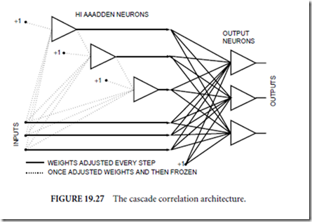
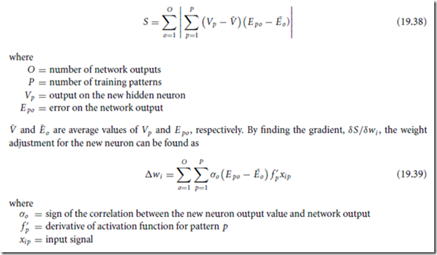
The cascade correlation architecture was proposed by Fahlman and Lebiere (1990). The process of net- work building starts with a one-layer neural net work and hidden neurons are added as needed. The network architecture is shown in Fig. 19.27. In each training step, a new hidden neuron is added and its weights are adjusted to maximize the magnitude

image

of the correlation between the new hidden neuron output and the residual error signal on the network output to be eliminated. The correlation parameter S must be maximized.

image

The output neurons are trained using the delta or quickprop algorithms. Each hidden neuron is trained just once and then its weights are frozen. The network learning and building process is completed when satisfactory results are obtained.

Radial Basis Function Networks

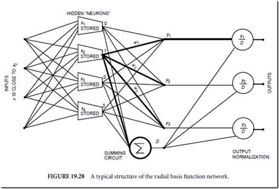
The structure of the radial basis network is shown in Fig. 19.28. This type of network usually has only one hidden layer with special neurons. Each of these neurons responds only to the inputs signals close to the stored pattern. The output signal hi of the i th hidden neuron is computed using formula

image

imageNote that the behavior of this “neuron” significantly differs form the biological neuron. In this “neuron,” excitation is not a function of the weighted sum of the input signals. Instead, the distance between the input and stored pattern is computed. If this distance is zero then the neuron responds with a maximum output magnitude equal to one. This neuron is capable of recognizing certain patterns and generating output signals that are functions of a similarity. Features of this neuron are much more powerful than a neuron used in the backpropagation networks. As a consequence, a network made of such neurons is also more powerful.

If the input signal is the same as a pattern stored in a neuron, then this neuron responds with 1 and remaining neurons have 0 on the output, as is illustrated in Fig. 19.28. Thus, output signals are exactly equal to the weights coming out from the active neuron. This way, if the number of neurons in the hidden layer is large, then any input/output mapping can be obtained. Unfortunately, it may also happen that for some patterns several neurons in the first layer will respond with a nonzero signal. For a proper approximation, the sum of all signals from the hidden layer should be equal to one. To meet this requirement, output signals are often normalized as shown in Fig. 19.28.

The radial-based networks can be designed or trained. Training is usually carried out in two steps. In the first step, the hidden layer is usually trained in the unsupervised mode by choosing the best patterns for cluster representation. An approach, similar to that used in the WTA architecture can be used. Also in this step, radii σi must be found for a proper overlapping of clusters.

The second step of training is the error backpropagation algorithm carried on only for the output layer.

Since this is a supervised algorithm for one layer only, the training is very rapid, 100–1000 times faster than in the backpropagation multilayer network. This makes the radial basis-function network very attractive.

Also, this network can be easily modeled using computers, however, its hardware implementation would be difficult.

image


Neural Networks and Fuzzy Systems , Neuron cell and Feedforward Neural Networks.

Neural Networks and Fuzzy Systems
New and better electronic devices have inspired researchers to build intelligent machines operating in a fashion similar to the human nervous system. Fascination with this goal started when McCulloch and Pitts (1943) developed their model of an elementary computing neuron and when Hebb (1949) introduced his learning rules. A decade latter Rosenblatt (1958) introduced the perceptron concept. In the early 1960s Widrow and Holf (1960, 1962) developed intelligent systems such as ADALINE and MADALINE. Nillson (1965) in his book Learning Machines summarized many developments of that time. The pub- lication of the Mynsky and Paper (1969) book, with some discouraging results, stopped for sometime the fascination with artificial neural networks, and achievements in the mathematical foundation of the backpropagation algorithm by Werbos (1974) went unnoticed. The current rapid growth in the area of neural networks started with the Hopfield (1982, 1984) recurrent network, Kohonen (1982) unsupervised training algorithms, and a description of the backpropagation algorithm by Rumelhart et al. (1986).
Neuron cell

A biological neuron is a complicated structure, which receives trains of pulses on hundreds of excitatory and inhibitory inputs. Those incoming pulses are summed with different weights (averaged) during the time period of latent summation. If the summed value is higher than a threshold, then the neuron itself is generating a pulse, which is sent to neighboring neurons. Because incoming pulses are summed with time, the neuron generates a pulse train with a higher frequency for higher positive excitation. In other words, if the value of the summed weighted inputs is higher, the neuron generates pulses more frequently. At the same time, each neuron is characterized by the nonexcitability for a certain time after the firing pulse. This so-called refractory period can be more accurately described as a phenomenon where after excitation the threshold value increases to a very high value and then decreases gradually with a certain time constant. The refractory period sets soft upper limits on the frequency of the output pulse train. In the biological neuron, information is sent in the form of frequency modulated pulse trains.

This description of neuron action leads to a very complex neuron model, which is not practical. McCulloch and Pitts (1943) show that even with a very simple neuron model, it is possible to build logic and memory circuits. Furthermore, these simple neurons with thresholds are usually more powerful than typical logic gates used in computers. The McCulloch-Pitts neuron model assumes that incoming and outgoing signals may have only binary values 0 and 1. If incoming signals summed through positive or negative weights have a value larger than threshold, then the neuron output is set to 1. Otherwise, it is set to 0.

image

image

Examples of McCulloch-Pitts neurons realizing OR, AND, NOT, and MEMORY operations are shown in Fig. 19.13. Note that the structure of OR and AND gates can be identical. With the same structure, other logic functions can be realized, as Fig. 19.14 shows.

The perceptron model has a similar structure. Its input signals, the weights, and the thresholds could have any positive or negative values. Usually, instead of using variable threshold, one additional constant input with a negative or positive weight can added to each neuron, as Fig. 19.15 shows. In this case, the threshold is always set to be zero and the net value is calculated as

image

image

These continuous activation functions allow for the gradient-based training of multilayer networks. Typical activation functions are shown in Fig. 19.16. In the case when neurons with additional threshold input are used (Fig. 19.15(b)), the λ parameter can be eliminated from Eqs. (19.6) and (19.7) and the steepness of the neuron response can be controlled by the weight scaling only. Therefore, there is no real need to use neurons with variable gains.

Note, that even neuron models with continuous activation functions are far from an actual biological neuron, which operates with frequency modulated pulse trains.

Feedforward Neural Networks

Feedforward neural networks allow only one directional signal flow. Furthermore, most feedforward neural networks are organized in layers. An example of the three-layer feedforward neural network is shown in Fig. 19.17. This network consists of input nodes, two hidden layers, and an output layer.

image

image

A single neuron is capable of separating input patterns into two categories, and this separation is linear. For example, for the patterns shown in Fig. 19.18, the separation line is crossing x1 and x2 axes at points x10 and x20. This separation can be achieved with a neuron having the following weights: w1 = 1/x10, w2 = 1/x20, and w3 = −1. In general for n dimensions, the weights are

image

One neuron can divide only linearly separated patterns. To select just one region in n-dimensional input space, more than n + 1 neurons should be used. If more input clusters are to be selected, then the number of neurons in the input (hidden) layer should be properly multiplied. If the number of neurons in the input (hidden) layer is not limited, then all classification problems can be solved using the three-layer network. An example of such a neural network, classifying three clusters in the two-dimensional space, is shown in Fig. 19.19. Neurons in the first hidden layer create the separation lines between input clusters. Neurons in the second hidden layer perform the AND operation, as shown in Fig. 19.13(b). Output neurons perform the OR operation as shown in Fig. 19.13(a), for each category. The linear separation property of neurons makes some problems specially difficult for neural networks, such as exclusive OR, parity computation for several bits, or to separate patterns laying on two neighboring spirals.

The feedforward neural network is also used for nonlinear transformation (mapping) of a multidimensional input variable into another multidimensional variable in the output. In theory, any input-output mapping should be possible if the neural network has enough neurons in hidden layers (size of output layer is set by the number of outputs required). In practice, this is not an easy task. Presently, there is no satisfactory method to define how many neurons should be used in hidden layers. Usually, this is found by the trial-and-error method. In general, it is known that if more neurons are used, more complicated

imageshapes can be mapped. On the other hand, networks with large numbers of neurons lose their ability for generalization, and it is more likely that such networks will also try to map noise supplied to the input.


Process , Select the Right Paradigm and then Automate and Defining Terms .

Process

Derived from the combination of steps taken to solve the problems of traditional systems engineering and software development, each DBTF system is defined with built-in quality, built-in productivity and built-in control (like the biological superorganism). The process combines mathematical perfection with engineering precision. Its purpose is to facilitate the “doing things right in the first place” development style, avoiding the “fixing wrong things up” traditional approach. Its automation is developed with the following considerations: error prevention from the early stage of system definition, life cycle control of the system under development, and inherent reuse of highly reliable systems. The development life cycle is divided into a sequence of stages, including: requirements and design modeling by formal specification and analysis; automatic code generation based on consistent and logically complete models; test and execution; and simulation.

The first step is to define a model with the language. This process could be in any phase of the develop- mental life cycle, including problem analysis, operational scenarios, and design. The model is automatically analyzed to ensure that it was defined properly. This includes static analysis for preventive properties and dynamic analysis for user intent properties. In the next stage, the generic source code generator automatically generates a fully production-ready and fully integrated software implementation for any kind or size of application, consistent with the model, for a selected target environment in the language and architecture of choice. If the selected environment has already been configured, the generator selects that environment directly; otherwise, the generator is first configured for a new language and architecture.

Because of its open architecture, the generator can be configured to reside on any new architecture (or interface to any outside environment), e.g., to a language, communications package, an internet interface, a database package, or an operating system of choice; or it can be configured to interface to the users own legacy code. Once configured for a new environment, an existing system can be automatically regenerated to reside on that new environment. This open architecture approach, which lends itself to true component based development, provides more flexibility to the user when changing requirements or architectures; or when moving from an older technology to a newer one.

It then becomes possible to execute the resulting system. If it is software, the system can undergo testing for further user intent errors. It becomes operational after testing. Application changes are made to the requirements definition—not to the code. Target architecture changes are made to the configuration of the generator environment (which generates one of a possible set of implementations from the model)—not to the code. If the real system is hardware or peopleware, the software system serves as a simulation upon which the real system can be based. Once a system has been developed, the system and the process used to develop it are analyzed to understand how to improve the next round of system development.

Seamless integration is provided throughout from systems to software, requirements to design to code to tests to other requirements and back again; level to level, and layer to layer. The developer is able to trace from requirements to code and back again.

Given an automation that has these capabilities, it should be no surprise that it has been defined with itself and that it continues to automatically generate itself as it evolves with changing architectures and changing technologies. Table 19.2 contains a summary of some of the differences between the more modern preventative paradigm and the traditional approach.

A relatively small set of things is needed to master the concepts behind DBTF. Everything else can be derived, leading to powerful reuse capabilities for building systems. It quickly becomes clear why it is no longer necessary to add features to the language or changes to a developed application in an ad hoc fashion, since each new aspect is ultimately and inherently derived from its mathematical foundations.

Although this approach addresses many of the challenges and solves many of the problems of traditional software environments, it could take time before this paradigm (or one with similar properties) is adopted by the more mainstream users, since it requires a change to the corporate culture. The same has been true in related fields. At the time when the computer was first invented and manual calculators were used for almost every computation; it has been said that it was believed by hardware pioneers like Ken Olson, founder of Digital Equipment Corporation, that there would only be a need for four computers in the world. It took awhile for the idea of computers and what they were capable of to catch on. Such could be the case for a more advanced software paradigm as well. That is, it could take awhile for software to be truly something to manufacture as opposed to being handcrafted as it is in today’s traditional development environments.

Select the Right Paradigm and then Automate

Where software engineering fails is in its inability to grasp that not only the right paradigm (out of many paradigms) must be selected, but that the paradigm must be part of an environment that provides an inherent and integrated automated means to solve the problem at hand. What this means is that the paradigm must be coupled with an integrated set of tools with which to implement the results of utilizing the paradigm to design and develop the system. Essentially, the paradigm generates the model and a toolset must be provided to generate the system.

Businesses that expected a big productivity payoff from investing in technology are, in many cases, still waiting to collect. A substantial part of the problem stems from the manner in which organizations are building their automated systems. Although hardware capabilities have increased dramatically, organizations are still mired in the same methodologies that saw the rise of the behemoth mainframes. Obsolete methodologies simply cannot build new systems.

There are other changes as well. Users demand much more functionality and flexibility in their systems. And given the nature of many of the problems to be solved by this new technology, these systems must also be error free.

image

Where the biological superorganism has built-in control mechanisms fostering quality and productivity, up until now, the silicon superorganism has had none. Hence, the productivity paradox. Often, the only way to solve major issues or to survive tough times is through nontraditional paths or innovation. One must create new methods or new environments for using new methods. Innovation for success often starts with a look at mistakes from traditional systems. The first step is to recognize the true root problems, then categorize them according to how they might be prevented. Derivation of practical solutions is a logical next step. Iterations of the process entail looking for new problem areas in terms of the new solution environment and repeating the scenario. That is how DBTF came into being.

With DBTF, all aspects of system design and development are integrated with one systems language and its associated automation. Reuse naturally takes place throughout the life cycle. Objects, no matter how complex, can be reused and integrated. Environment configurations for different kinds of architectures can be reused. A newly developed system can be safely reused to increase even further the productivity of the systems developed with it.

This preventative approach can support a user in addressing many of the challenges presented in today’s software development environments. There will, however, always be more to do to capitalize on this technology. That is part of what makes a technology like this so interesting to work with. Because it is based on a different premise or set of assumptions (axioms), a significant number of things can and will change because of it. There is the continuing opportunity for new research projects and new products. Some problems can be solved, because of the language, that could not be solved before. Software development, as we have known it, will never be the same. Many things will no longer need to exist—they, in fact, will be rendered extinct, just as that phenomenon occurs with the process of natural selection in the biological system. Techniques for bridging the gap from one phase of the life cycle to another become obsolete. Techniques for maintaining the source code as a separate process are no longer needed, since the source is automatically generated from the requirements specification. Verification, too, becomes obsolete. Techniques for man- aging paper documents give way to entering requirements and their changes directly into the requirements specification database. Testing procedures and tools for finding most errors are no longer needed because those errors no longer exist. Tools to support programming as a manual process are no longer needed.

Compared to development using traditional techniques, the productivity of DBTF developed systems has been shown to be significantly greater (DOD, 1992; Krut, 1993; Ouyang, 1995; Keyes, 2000). Upon further analysis, it was discovered that the productivity was greater the larger and more complex the system—the opposite of what one finds with traditional systems development. This is, in pa2004rt, because of the high degree of DBTF’s support of reuse. The larger a system, the more it has the opportunity to capitalize on reuse. As more reuse is employed, productivity continues to increase. Measuring productivity becomes a process of relativity—that is, relative to the last system developed.

Capitalizing on reusables within a DBTF environment is an ongoing area of research interest1 (Hamilton, 2003–2004). An example is understanding the relationship between types of reusables and metrics. This takes into consideration that a reusable can be categorized in many ways. One is according to the manner in which its use saves time (which translates to how it impacts cost and schedules). More intelligent tradeoffs can then be made. The more we know about how some kinds of reusables are used, the more information we have to estimate costs for an overall system. Keep in mind, also, that the traditional methods for estimating time and costs for developing software are no longer valid for estimating systems developed with preventative techniques.

There are other reasons for this higher productivity as well, such as the savings realized and time saved due to tasks and processes that are no longer necessary with the use of this preventative approach. There is less to learn and less to do—less analysis, little or no implementation, less testing, less to manage, less to document, less to maintain, and less to integrate. This is because a major part of these areas has been automated or because of what inherently takes place because of the nature of the formal systems language. The paradigm shift occurs once a designer realizes that many of the old tools are no longer needed to design and develop a system. For example, with one formal semantic language to define and integrate all aspects of a system, diverse modeling languages (and methodologies for using them), each of which defines only part of a system, are no longer necessary. There is no longer a need to reconcile multiple techniques with semantics that interfere with each other.

Software is a relatively young technological field that is still in a constant state of change. Changing from a traditional software environment to a preventative one is like going from the typewriter to the word processor. Whenever there is any major change, there is always the initial overhead needed for learning the new way of doing things. But, as with the word processor, progress begets progress.

In the end, it is the combination of the methodology and the technology that executes it that forms the foundation of successful software. Software is so ingrained in our society that its success or failure will dramatically influence both the operation and the success of businesses and government. For that reason, today’s decisions about systems engineering and software development will have far reaching effects.

Collective experience strongly confirms that quality and productivity increase with the increased use of properties of preventative systems. In contrast to the “better late than never” after the fact philosophy, the preventative philosophy is to solve—or possible, prevent—a given problem as early as possible. This means finding a problem statically is better than finding it dynamically. Preventing it by the way a system is defined is even better. Better yet, is not having to define (and build) it at all.

Reusing a reliable system is better than reusing one that is not reliable. Automated reuse is better than manual reuse. Inherent reuse is better than automated reuse. Reuse that can evolve is better than one that cannot evolve. Best of all is reuse that approaches wisdom itself. Then, have the wisdom to use it. One such wisdom is that of applying a common systems paradigm to systems and software, unifying their understanding with a commonly held set of system semantics.

DBTF embodies a preventative systems approach, the language supports its representation, and its automation supports its application and use. Each is evolutionary (in fact, recursively so), with experience feeding the theory, the theory feeding the language, which in turn feeds the automation. All are used, in concert, to design systems and build software. The answer continues to be in the results just as in the biological system and the goal is that the systems of tomorrow will inherit the best of the systems of today.

Defining Terms

Data base management system (DBMS): The computer program that is used to control and provide rapid access to a database. A language is used with the DBMS to control the functions that a DBMS provides. For example, SQL is the language that is used to control all of the functions that a relational architecture based DBMS provides for its users, including data definition, data retrieval, data manipulation, access control, data sharing, and data integrity.

Graphical user interface (GUI): The ultimate user interface, by which the deployed system interfaces with the computer most productively, using visual means. Graphical user interfaces provide a series of intuitive, colorful, and graphical mechanisms which enable the end-user to view, update, and manipulate information.

Formal system: A system defined in terms of a known set of axioms (or assumptions); it is therefore mathematically based (for example, a DBTF system is based on a set of axioms of control). Some of its properties are that it is consistent and logically complete. A system is consistent if it can be shown that no assumption of the system contradicts any other assumption of that system. A system is logically complete if the assumptions of the method completely define a given set of properties. This assures that a model of the method has that set of properties. Other properties of the models defined with the method may not be provable from the method’s assumptions. A logically complete system has a semantic basis (i.e., a way of expressing the meaning of that system’s objects). In terms of the semantics of a DBTF system, this means it has no interface errors and is unambiguous, contains what is necessary and sufficient, and has a unique state identification.

Interface: A seam between objects, or programs, or systems. It is at this juncture that many errors surface.

Software can interface with hardware, humans, and other software.

Methodology: A set of procedures, precepts, and constructs for the construction of software.

Metrics: A series of formulas which measure such things as quality and productivity.

Operating system: A program that manages the application programs that run under its control.

Software architecture: The structure and relationships among the components of software.

Acknowledgment

The author is indebted to Jessica Keyes for her helpful suggestions.

References

Boehm, B.W. 1981. Software Engineering Economics. Prentice-Hall, Englewood Cliffs, NJ.

Booch, G., Rumbaugh, J., and Jacobson, I. 1999. The Unified Modeling Language User Guide. Addison- Wesley, Reading, MA.

Department of Defense. 1992. Software engineering tools experiment-Final report. Vol. 1, Experiment Summary, Table 1, p. 9. Strategic Defense Initiative, Washington, DC.

Goldberg, A. and Robson, D. 1983. Smalltalk-80 the Language and its Implementation. Addison-Wesley, Reading, MA.

Gosling, J., Joy, B., and Steele, G. 1996. The Java Language Specification, Addison-Wesley, Reading, MA.

Hamilton, M. 1994. Development before the fact in action. Electronic Design, June 13. ES.

Hamilton, M. 1994. Inside development before the fact. Electronic Design, April 4. ES.

Hamilton, M. (In press). System Oriented Objects: Development Before the Fact.

Hamilton, M. and Hackler, W.R. 2000. Towards Cost Effective and Timely End-to-End Testing, HTI, prepared for Army Research Laboratory, Contract No. DAKF11-99-P-1236.

HTI Technical Report, Common Software Interface for Common Guidance Systems, US. Army DAAE30- 02-D-1020 and DAAB07-98-D-H502/0180, Precision Guided Munitions, Under the direction of Cliff McLain, ARES, and Nigel Gray, COTR ARDEC, Picatinny Arsenal, NJ, 2003–2004.

Harbison, S.P. and Steele, G.L., Jr. 1997. C A Reference Manual. Prentice-Hall, Englewood Cliffs, NJ.

Jones, T.C. 1977. Program quality and programmer productivity. IBM Tech. Report TR02.764, Jan.: 80, Santa Teresa Labs., San Jose, CA.

Keyes, J. The Ultimate Internet Developers Sourcebook, Chapter 42, Developing Web Applications with 001, AMACOM.

Keyes, J. 2000. Internet Management, chapters 30–33, on 001-developed systems for the Internet, Auerbach.

Krut, B. Jr. 1993. Integrating 001 Tool Support in the Feature-Oriented Domain Analysis Methodology (CMU/SEI-93-TR-11, ESC-TR-93-188). Pittsburgh, PA: Software Engineering Institute, Carnegie-Mellon University.

Lickly, D. J. 1974. HAL/S Language Specification, Intermetrics, prepared for NASA Lyndon Johnson Space Center.

Lientz, B.P. and Swanson, E.B. 1980. Software Maintenance Management. Addison-Wesley, Reading, MA.

Martin, J. and Finkelstein, C.B. 1981. Information Engineering. Savant Inst., Carnforth, Lancashire, UK.

Meyer, B. 1992. Eiffel the Language. Prentice-Hall, New York.

NSQE Experiment: http://hometown.aol.com/ONeillDon/index.html, Director of Defense Research and Engineering (DOD Software Technology Strategy), 1992–2002.

Ouyang, M., Golay, M. W. 1995. An Integrated Formal Approach for Developing High Quality Software of Safety-Critical Systems, Massachusetts Institute of Technology, Cambridge, MA, Report No. MIT-ANP-TR-035.

Software Engineering Inst. 1991. Capability Maturity Model. Carnegie-Mellon University Pittsburgh, PA.

Stefik, M. and Bobrow, D.J. 1985. Object-Oriented Programming: Themes and Variations. AI Magazine, Zerox Corporation, pp. 40–62.

Stroustrup, B. 1994. The Design and Evolution of C++. AT&T Bell Laboratories, Murray Hill, NJ.

Stroustrup, B. 1997. The C++ Programming Language, Addison-Wesley, Reading, MA.

Yourdon E. and Constantine, L. 1978. Structured Design: Fundamentals of a Discipline of Computer

Program and Systems Design, Yourdan Press, New York.

Further Information

Hamilton, M. and Hackler, R. 1990. 001: A rapid development approach for rapid prototyping based on a system that supports its own life cycle. IEEE Proceedings, First International Workshop on Rapid System Prototyping (Research Triangle Park, NC) pp. 46–62, June 4.

Hamilton, M. 1986. Zero-defect software: The elusive goal. IEEE Spectrum 23(3):48–53, March. Hamilton, M. and Zeldin, S. 1976. Higher Order Software—A Methodology for Defining Software. IEEE

Transactions on Software Engineering, vol. SE-2, no. 1.

McCauley, B. 1993. Software Development Tools in the 1990s. AIS Security Technology for Space Operations Conference, Houston, Texas.

Schindler, M. 1990. Computer Aided Software Design. John Wiley & Sons, New York.

The 001 Tool Suite Reference Manual, Version 3, Jan. 1993. Hamilton Technologies Inc., Cambridge, MA.


Apollo On-Board Flight Software Effort: Lessons Learned , Development Before the Fact and Development Before the Fact Theory .

Apollo On-Board Flight Software Effort: Lessons Learned

The original purpose of the empirical study, which had its beginnings in 1968, was to learn from Apollo’ s flight software and its development in order to make use of this effort for future Apollo missions as well as for the then up and coming Skylab and Shuttle missions. A better way was needed to define and develop software systems than the ones being used and available, because the existing ones (just like the traditional ones today) did not solve the pressing problems. There was a driving desire to learn from experience; what could be done better for future systems and what should the designers and developers keep doing because they were doing it right. The search was in particular for a means to build ultra reliable software.

The results of the study took on multiple dimensions, not just for space missions but for systems in general; some of which were not so readily apparent for many years to come. The Apollo software, given what had to be accomplished and the time within which it had to be accomplished, was as complex as it could get; causing other software projects in the future to look (and be) less daunting than they might have been in comparison. The thought was if problems from a worst case scenario could be solved and simplified, the solutions might be able to be applied to all kinds of systems.

On hindsight, this was an ideal setting from which to understand systems and software and the kinds of problems that can occur and issues that need to be addressed. Because of the nature of the Apollo software there was the opportunity to make just about every kind of error possible, especially since the software was being developed concurrently with the planning of the space missions, the hardware, the simulator, and the training of the astronauts (demonstrating how much the flight software was part of a larger system of other software, hardware and peopleware); and since no one had been to the moon before there were many unknowns. In addition the developers were under the gun with what today would have been unrealistic expectations and schedules. This and what was accomplished (or not accomplished) provided a wealth of information from which to learn. Here are some examples:

It was found during the Apollo study that interface errors (errors resulting from ambiguous relationships, mismatches, conflicts in the system, poor communication, lack of coordination, inability to integrate) accounted for approximately 75% of all the errors found in the software during final testing, the Verification and Validation (V&V) phase (using traditional development methods the figure can be as high as 90%); interface errors include data flow, priority and timing errors from the highest levels of a system to the lowest levels of a system, to the lowest level of detail. It was also determined that 44% of the errors were found by manual means (suggesting more areas for automation) and that 60% of the errors had unwittingly existed in earlier missions—missions that had already flown, though no errors occurred (made themselves known) during any flights. The fact that this many errors existed in earlier missions was down-right frightening. It meant lives were at stake during every mission that was flown. It meant more needed to be done in the area of reliability. Although no software problem ever occurred (or was known to occur) on any Apollo mission, it was only because of the dedication of the software team and the methods they used to develop and test the software.

A more detailed analysis of interface errors followed; especially since they not only accounted for the majority of errors but they were often the most subtle errors and therefore the hardest to find. The realization was made that integration problems could be solved if interface problems could be solved and if integration problems could be solved, there would be traceability. Each interface error was placed into a category according to the means that could have been taken to prevent it by the very way a system was defined. It was then established that there were ways to prevent certain errors from happening simply by changing the rules of definition. This work led to a theory and methodology for defining a system that would eliminate all interface errors.

It quickly became apparent that everything including software is a system and the issues of system design were one and the same as those of software. Many things contributed to this understanding of what is meant by the concept of “system.” During development of the flight software, once the software group implemented the requirements (“thrown over the wall” by system design experts to the software people), the software people necessarily became the new experts. This phenomenon forced the software experts to become system experts (and vice versa) suggesting that a system was a system whether in the form of higher level algorithms or software that implemented those algorithms.

Everyone learned to always expect the unexpected and this was reflected in every design; that is, they learned to think, plan and design in terms of error detection and recovery, reconfiguration in real time; and to always have backup systems. The recognition of the importance of determining and assigning (and ensuring) unique priorities of processes was established as part of this philosophy. Towards this end it was also established that a “kill and start over again” restart approach to error detection and recovery was far superior as opposed to a “pick up from where you left off ” approach; and it simplified both the operation of the software as well as the development and testing of the software. The major impact a system design for one part of the software could have on another part further emphasized that everything involved was part of a system—the “what goes around comes around” syndrome. For example, choosing an asynchronous executive (one where higher priority processes can interrupt lower priority processes) for the flight software not only allowed for more flexibility during the actual flights but it also provided for more flexibility to make a change more safely and in a more modular fashion during development of the flight software.

It became obvious that testing was never over (even with many more levels of testing than with other kinds of applications; and with added testing by independent verification and validation organizations). This prompted a search for better methods of testing. Again, traditional methods were not solving the problem. With the realization that most of the system design and software development processes could be mechanized (and the same generic processes were being performed throughout each of all phases of development), it became clear they could be automated. This suggested an environment that would do just that, automate what traditional systems still to this day do manually. In addition, for the space missions, software was being developed for many missions all at once and in various stages, leading the way to learn how to successfully perform distributed development.

It was learned during this process of evaluation of space flight software that traditional methods did not support developers in many areas and allowed too much freedom in other areas (such as freedom to make errors, both subtle and serious) and not enough freedom in other areas (such as areas that required an open architecture and the ability to reconfigure in real time to be successful). It further became clear that a new kind of language was needed to define a system having certain “built-in” properties not available in traditional languages; such as inherent reliability, integration, reuse, and open architecture capabilities provided simply by the use of the language itself. In addition it was realized a set of tools could be developed to support such a language as well as take away tedious mechanical processes that could become automated, thus avoiding even further errors, reducing the need for much after the fact testing. It was only later understood the degree to which systems with “built-in reliability” could increase the productivity in their development, resulting in “built-in productivity.”

Lessons learned from this effort continue today. Key aspects are that systems are asynchronous in nature and this should be reflected inherently in the language used to define systems. Systems should be assumed to be event driven and every function to be applied should have a unique priority; real time event and priority driven behavior should be part of the way one specifies a system in a systems language and not defined on a case by case basis and in different programming languages with special purpose data types.

Rather than having a language whose purpose is to run a machine the language should naturally describe what objects there are and what actions they are taking. Objects are inherently distributed and their interactions asynchronous with real time, event-driven behavior. This implies that one could define a system and its own definition would have the necessary behaviors to characterize natural behavior in terms of real time execution semantics. Application developers would no longer need to explicitly define schedules of when events were to occur. Events would instead occur when objects interact with other objects. By describing the interactions between objects the schedule of events is inherently defined.

The result of this revelation was that a universal systems language could be used to tackle all aspects of a system: its planning, development, deployment, and evolution. This means that all the systems that work together during the system’s lifecycle can be defined and understood using the same semantics.

Development Before the Fact

Once the analysis of the Apollo effort was completed, the next step was to create (and evolve) a new mathematical paradigm from the “heart and soul” of Apollo; one that was preventative instead of curative in its approach. A theory was derived for defining a system such that the entire class of errors, known as interface errors, would be eliminated. The first generation technology derived from this theory concentrated on defining and building reliable systems in terms of functional hierarchies (Hamilton, 1986). Having realized the benefits of addressing one major issue, that is, reliability, just by the way a system is defined, the research effort continued over many years (and still continues) to evolve the philosophy of addressing this issue further as well as addressing other issues the same way, that is, using language mechanisms that inherently eliminate software problems. The result is a new generation technology called development before the fact (DBTF) (see Fig. 19.12) where systems are designed and built with preventative properties integrating all aspects of a system’s definition including the inherent integration of functional and type hierarchical networks, (Hamilton and Hackler, in press; Hamilton, 1994; Hamilton, 1994; Keyes, 2001), http://www.htius.com/.

image

Development before the fact is a system oriented object (SOO) approach based on a concept of control that is lacking in other software engineering paradigms. At the base of the theory that embodies every system are a set of axioms—universally recognized truths—and the design for every DBTF system is based on these axioms and on the assumption of a universal set of objects. Each axiom defines a relation of immediate domination. The union of the relations defined by the axioms is control. Among other things, the axioms establish the control relationships of an object for invocation, input and output, input and output access rights, error detection and recovery, and ordering during its developmental and operational states. Table 19.1 summarizes some of the properties of objects within these systems.

Combined with further research it became clear that the root problem with traditional approaches is that they support users in “fixing wrong things up rather than in “doing things the right way in the first place.” Instead of testing software to look for errors after the software is developed, with the new paradigm, software could now be defined to not allow errors in, in the first place; correctness could be accomplished by the very way software is defined, by “built-in” language properties; what had been created was a universal semantics for defining not just software systems but systems in general.

Once understood, it became clear that the characteristics of good design can be reused by incorporating them into a language for defining any system (not just a software system). The language is a formalism for representing the mathematics of systems. This language—actually a meta-language—is the key to DBTF. Its main attribute is to help the designer reduce the complexity and bring clarity into his thinking process, eventually turning it into the ultimate reusable, wisdom, itself. It is a universal systems language for defining systems, each system of which can be incorporated into the meta-language and then used to define other systems. A system defined with this language has properties that come along “for the ride” that in essence control its own destiny. Based on a theory (DBTF) that extends traditional mathematics of systems with a unique concept of control, this formal but friendly language has embodied within it a natural representation of the physics of time and space. 001AXES evolved as DBTF’s formal universal systems language, and the 001 Tool Suite as its automation.

image

image

The creation of the concept of reuse definition scenarios during Apollo to save time in development and space in the software was a predecessor to the type of higher level language statements used within the systems language. This included horizontal and vertical reuse that led to a flexible open architecture within the DBTF environment.

Understanding the importance of metrics and the influence it could have on future software has had a major focus throughout this endeavor. What this approach represents, in essence, is the current state of a “reusable” originally based on and learned from Apollo followed by that learned from each of its evolving states. It reuses and builds on that which was (and is) observed to have been beneficial to inherit as well as the avoidance of that observed not to have been beneficial. That learned from history was and will continue to be put into practice for future projects. Someone once said “it is never surprising when something developed empirically turns out to have intimate connections with theory.” Such is the case with DBTF .

Development Before the Fact Theory

Mathematical approaches have been known to be difficult to understand and use. They have also been known to be limited in their use for nontrivial systems as well as for much of the life cycle of a given system. What makes DBTF different in this respect is that the mathematics it is based on, has been extended for handling the class of systems that software falls into; the formalism along with its unfriendliness is “hidden” under the covers by language mechanisms derived in terms of that formalism; and the technology based on this formalism has been put to practical use.

With DBTF, all models are defined using its language (and developed using its automated environment) as SOOs. A SOO is understood the same way without ambiguity by all other objects within its environment—including all users, models, and automated tools. Each SOO is made up of other SOOs. Every aspect of a SOO is integrated not the least of which is the integration of its object oriented parts with its function oriented parts and its timing oriented parts. Instead of systems being object-oriented, objects are systems-oriented. All systems are objects. All objects are systems. Because of this, many things heretofore not believed possible with traditional methods are possible, much of what seems counter intuitive with traditional approaches, that tend to be software centric, becomes intiutive with DBTF, which is system centric. DBTF’s automation provides the means to support a system designer or software developer in following its paradigm throughout a system’s design or software development life cycle. Take for example, testing. The more a paradigm prevents errors from being made in the first place the less the need for testing and the higher the productivity. Before the fact testing is inherently part of every development step. Most errors

are prevented because of that which is inherent or automated.

Unlike a language such as UML or Java that is limited to software, 001AXES is a systems language and as such can be used to state not just software phenomenon but any given system phenomenon. UML is a graphical software specification language. 001AXES is a graphical system specification language. They have different purposes. At some point UML users have to program in some programming language, but 001AXES users do not; a system can be completely specified and automatically generated with all of its functionality, object and timing behavior without a line of code being written. The intent of UML is to run a machine. The intent of 001AXES is to define (and if applicable, execute) a system software or otherwise.

Because 001AXES is a systems language, its semantics is more general than a software language. For example, 001AXES defined systems could run on a computer, person, autonomous robot, or an organization; whereas the content of the types (or classes) in a software language is based on a computer that runs software.

Because 001AXES is systemic in nature it capitalizes upon that which is common to all systems; including software, financial, political, biological, and physical systems. For software the semantics of 001AXES is mapped to appropriate constructs for each of a possible set of underlying programming language implementations. Unlike the DBTF approach, in general these more traditional development approaches emphasize a fragmented approach to the integrated specification of a system and its software, short changing integration and automation in the development process. A more detailed discussion of 001AXES and UML can be found in (Hamilton and Hackler, 2000).


The Nature of Software Engineering , A New Approach .

The Nature of Software Engineering

images (1)

Engineers often use the term systems engineering to refer to the tasks of specifying, designing, and simulating a non-software system such as a bridge or electronic component. Although software may be used for simulation purposes, it is but one part of the systems engineering process. Software engineering, on the other hand, is concerned with the production of nothing but software. In the 1970s industry pundits began to notice that the cost of producing large-scale systems was growing at a high rate and that many projects were failing or, at the very least, resulting in unreliable products. Dubbed the software crisis, its manifestations were legion, and the most important include

Programmer productivity: In government in the 1980s, an average developer using C was expected to produce only 10 lines of production code per day (an average developer within a commercial organization was expected to produce 30 lines a month); today the benchmark is more like two to five lines a day while at the same time the need is dramatically higher than that, perhaps by several orders of magnitude, ending up with a huge backlog. The National Software Quality Experiment (NSQE) completed a 10-year research project in 2002 that compared the productivity of systems today with that of systems 10 years ago. The assumption at the outset was that the productiviity of today’s systems would be much higher given all the more “modern” tools including a proliferation of commercial packages and object-oriented languages that are now available; but they were wrong. Not only did the productivity not increase, it decreased (NSQE, 2002). Further NSQE concluded that there would need to be a significant breakout in the way software is designed and developed in order to achieve a factor of 10 reduction in defect rate.

Programmer productivity is dependent on a plethora of vagaries: from expertise to complexity of the problem to be coded to size of the program that is generated (Boehm, 1981). The science of measuring the quality and productivity of the software engineering process is called metrics. As in the diverse paradigms in software engineering itself, there are many paradigms of software measurement. Today’s metric formulas are complex and often take into consideration the following: cost, time to market, productivity on prior projects, data communications, distributed functions, performance, heavily used configurations, transaction rates, online data entry, end user efficiency, online update, processing complexity, reusability, installation ease, operational ease, and multiplicity of operational sites.

Defect removal costs: The same variables that affect programmer productivity affect the cost of debugging the programs and objects generated by those programmers. It has been observed that the testing and correcting of programs consumes a large share of the overall effort.

Development environment: Development tools and development practices greatly affect the quantity and quality of software. Most of today’s design and programming environments contain only a fragment of what is really needed to develop a complete system. Life cycle development environments provide a good example of this phenomena. Most of these tools can be described either as addressing the upper part of the life cycle (i.e., they handle the analysis and design) or the lower part of the life cycle (i.e., they handle code generation). There are few integrated tools on the market (i.e., that seamlessly handle both upper and lower functionalities). There are even fewer tools that add simulation, testing and cross-platform generation to the mix. And it would be hard put to find any tools that seamlessly integrate system design to software development.

GUI development: Developing graphical user interfaces is a difficult and expensive process unless the proper tools are used. The movement of systems from a host-based environment to the work station PC saw the entry of a plethora of GUI development programs onto the marketplace. But, unfortunately, the vast majority of these GUI-based tools do not have the capability of developing the entire system (i.e., the processing component as opposed to merely the front end). This leads to fragmented and error-prone systems. To be efficient, the GUI builder must be well integrated into the software development environment.

The result of these problems is that most of today’s systems require more resources allocated to maintenance than to their original development. Lientz and Swanson (1980) demonstrate that the problem is, in fact, larger than the one originally discerned during the 1970s. Software development is indeed complex and the limitations on what can be produced by teams of software engineers given finite amounts of time, budgeted dollars, and talent have been amply documented (Jones, 1977).

Essentially the many paradigms of software engineering attempt to rectify the causes of declining productivity and quality. Unfortunately this fails because current paradigms treat symptoms rather than the root problem. In fact, software engineering is itself extremely dependent on both the underlying systems software (for example, the operating systems) and hardware as well as the business environments upon which they sit.

SEI’s process maturity grid very accurately pinpoints the root of most of our software development problems. The fact that a full 86% of the organizations studied, remain at the ad hoc or chaotic level indicates that only a few organizations (the remaining 14%) have adopted any formal process for software engineering. Simply put, 86% of all organizations react to a business problem by just writing code. If they do employ a software engineering discipline, in all likelihood, it is one that no longer fits the requirements of the ever evolving business environment.

In the 1970s, the structured methodology was popularized. Although there were variations on the theme (i.e., different versions of the structured technique included the popular Gane/Sarson method and Yourdon method), for the most part, it provided methodology to develop usable systems in an era of batch computing. In those days, on-line systems with even the dumbest of terminals were a radical concept and graphical user interfaces were as unthinkable as the fall of the Berlin Wall.

Although times have changed and today’s hardware is a thousand times more powerful than when structured techniques were introduced, this technique still survives. And survives in spite of the fact that the authors of these techniques have moved on to more adaptable paradigms, and more modern software development and systems engineering environments have entered the market.

In 1981 Finkelstein and Martin (Martin, 1981) popularized information engineering for the more commercially oriented users (i.e., those whose problems to be solved tended to be more database centered), which, to this day, is quite popular amongst mainframe developers with an investment in CASE. Information engineering is essentially a refinement of the structured approach. Instead of focusing on the data so preeminent in the structured approach, however, information engineering focuses on the information needs of the entire organization. Here business experts define high-level information models, as well as detailed data models. Ultimately the system is designed from these models.

Both structured and information engineering methodologies have their roots in mainframe-oriented commercial applications. Today’s migration to client/server technologies (where the organization’s data can be spread across one or more geographically distributed servers while the end-user uses his or her GUI of choice to perform local processing) disables most of the utility of these methodologies. In fact, many issues now surfacing in more commercial applications are not unlike those addressed earlier in the more engineering oriented environments such as tele-communications and avionics. Client/server environments are characterized by their diversity. One organization may store its data on multiple databases, program in several programming languages, and use more than one operating system and, hence, differ- ent GUIs. Since software development complexity is increased a hundredfold in this new environment, a better methodology is required. Today’s object-oriented techniques solve some of the problem. Given the complexity of client/server, code trapped in programs is not flexible enough to meet the needs of this type of environment. We have already discussed how coding via objects rather than large programs engenders flexibility as well as productivity and quality through reusability. But object-oriented development is a double-edged sword.

While it is true that to master this technique is to provide dramatic increases in productivity, the sad fact of the matter is that object-oriented development, if done inappropriately, can cause problems far greater than problems generated from structured techniques. The reason for this is simple: the stakes are higher. Object-oriented environments are more complex than any other, the business problems chosen to be solved by object-oriented techniques are far more complex than other types of problems, and there are no conventional object-oriented methodologies and corollary tools to help the development team develop systems that are truly reliable. There are many kinds of object orientation. But with this diversity comes some very real risks. As a result, the following developmental issues must be considered before the computer is even turned on.

Integration is a challenge and needs to be considered at the onset. With traditional systems, developers rely on mismatched modeling methods to capture aspects of even a single definition. Whether it be integration of object to object, module to module, phase to phase, or type of application to type of application, the process can be an arduous one. The mismatch of evolving versions of point products (where a point product is able to be used for developing only an aspect of an application) used in design and development compounds the issue. Integration is usually left to the devices of myriad developers well into development. The resulting system is sometimes hard to understand and objects are difficult to trace. The biggest danger is that there is little correspondence to the real world. Interfaces are often incompatible and errors propagate throughout development. As a result, systems defined in this manner can be ambiguous and just plain incorrect.

Errors need to be minimized. Traditional methods as well as traditional object-oriented methods actually encourage the propagation of errors, such as reuse of unreliable objects with embedded and inherited errors. Internet viruses, worms, packet storms, trojans, and other malicious phenomenon are inexcusable and should be the exception not the rule. To be successful, errors must be eliminated from the very onset of the development process, including in the operating systems and related systems.

Languages need to be more formal. Whereas some languages are formal and others friendly, it is hard to find a language both formal and friendly. Within environments where more informal languages are used, lack of traceability and an overabundance of interface errors are a common occurrence. Within environments that have more formal languages their application has been found to be impractical for real world systems of any size or complexity. Recently, more modern software requirements languages have been introduced (for example, the Unified Modeling Language, UML (Booch et al., 1999), most of which are informal (or semi-formal); some of these languages were created by “integrating” several languages into one. Unfortunately, the bad comes with the good—often, more of what is not needed and less of what is needed; and since much of the formal part is missing, a common semantics needs to exist to reconcile differences and eliminate redundancies.

Flexibility for change and handling the unpredictable needs to be dealt with up front. Too often it is forgotten that the building of an application must take into account its evolution. In the real world, users change their minds, software development environments change and technologies change. Definitions of requirements in traditional development scenarios concentrate on the application needs of the user, but without consideration of the potential for the user’s needs or environment to change. Porting to a new environment becomes a new development for each new architecture, operating system, database, graphics environment, language, or language configuration. Because of this, critical functionality is often avoided for fear of the unknown, and maintenance, the most risky and expensive part of a system’s life cycle, is left unaccounted for during development. To address these issues, tools and techniques must be used to allow cross technology and changing technology solutions as well as provide for changing and evolving architectures. The syndrome of locked-in design needs to be eliminated. Often, developers are forced to develop in terms of an implementation technology that does not have an open architecture, such as a specific database schema or a graphical user interface (GUI). Bad enough is to attempt an evolution of such a system; worse yet is to use parts of it as reusables for a system that does not rely on those technologies. Well thought out and for- mal business practices and their implementation will help to minimize this problem within an organization. Developers must prepare for parallelism and distributed environments. Often, when it is not known that a system is targeted for a distributed environment, it is first defined and developed for a single processor environment and then changed/redeveloped for a distributed environment—an unproductive use of resources. Parallelism and distribution need to be dealt with at the very start of the project.

Resource allocation should be transparent to the user. Whether or not a system is allocated to distributed, asynchronous, or synchronous processors and whether or not two processors or ten processors are selected; with traditional methods it is still up to the designer and developer to be concerned with manually incorporating such detail into the application. There is no separation between the specification of what the system is to do vs. how the system does it. This results in far too much implementation detail to be included at the level of design. Once such a resource architecture becomes obsolete, it is necessary to redesign and redevelop those applications which have old designs embedded within them.

The creation of reliable reusable definitions must be promoted, especially those that are inherently provided.

Traditional requirements definitions lack the facilities to help find, create, use and ensure commonality in systems. Modelers are forced to use informal and manual methods to find ways to divide a system into components natural for reuse. These components do not lend themselves to integration and, as a result, they tend to be error-prone. Because these systems are not portable or adaptable, there is little incentive for reuse. In conventional methodologies, redundancy becomes a way of doing business. Even when methods are object oriented, developers are often left to their own devices to explicitly make their applications become object oriented; because these methods do not support all that which is inherent in an object.

Automation that minimizes manual work needs to replace “make work” automated solutions. In fact, automation itself is an inherently reusable process. If a system does not exist for reuse, it certainly does not exist for automation. But most of today’s development process is needlessly manual. Today’s systems are defined with insufficient intelligence for automated tools to use them as input. In fact, these automated tools concentrate on supporting the manual process instead of doing the real work. Typically, developers receive definitions that they manually turn into code. A process that could have been mechanized once for reuse is performed manually again and again. Under this scenario, even when automation attempts to do the real work, it is often incomplete across application domains or even within a domain, resulting in incomplete code, such as shell code (code that is an outline for real code). The generated code is often inefficient or hard wired to an architecture, a language, or even a version of a language. Often partial automations need to be integrated with incompatible partial automations or manual processes. Manual processes are needed to complete unfinished automations.

Run-time performance analysis (decisions between algorithms or architectures) should be based on formal definitions. Conventional system definitions contain insufficient information about a system’s run-time performance, including that concerning the decisions between algorithms or architectures. Design decisions where this separation is not taken into account thus depend on analysis of outputs from ad hoc implementations and associated testing scenarios. System definitions must consider how to separate the target system from its target environment.

Design integrity is the first step to usable systems. It is not known if a design is a good one until its implementation has failed or succeeded. Spiral development (an evolutionary approach) as opposed to waterfall development (where each phase of development is completed before the next phase is begun) helps address some of this issue. Usually, a system design is based on short-term considerations because knowledge is not reused from previous lessons learned. Development, ultimately, is driven toward failure. Once issues like these are addressed, software costs less and takes less time to develop. But, time is of the essence. These issues are becoming more complex and even more critical as developers prepare for the distributed environments that go hand in hand with the increasing predominance of the internet.

Thus far this chapter has explained the derivation of software and attempted to show how it has evolved over time to become the true brains of any automated system. But like a human brain, this software brain must be carefully architected to promote productivity, foster quality, and enforce control and reusability.

Traditional software engineering paradigms fail to see the software development process from the larger perspective of the superorganism described at the beginning of this chapter. It is only when we see the software development process as made up of discrete but well-integrated components, can we begin to develop a methodology that can produce the very benefits that have been promised by the advent of software decades ago.

Software engineering, from this perspective, consists of a methodology as well as a series of tools with which to implement the solution to the business problem at hand. But even before the first tool can be applied, the software engineering methodology must be deployed to assist in specifying the requirements of the problem. How can this be accomplished successfully in the face of the problems outlined? How can it be accomplished in situations where organizations must develop systems that run across diverse and distributed hardware platforms, databases, programming languages, and GUIs when traditional methodologies make no provision for such diversity? And how can software be developed without having to fix or cure those myriad of problems that result “after the fact” of that software’s development?

To address these software issues, an organization has several options, ranging from one extreme to the other. The options include (1) keep doing things the same way; (2) add tools and techniques that support business as usual but provide relief in selected areas; (3) bring in more modern but traditional tools and techniques to replace existing ones; (4) use a new paradigm with the most advanced tools and techniques that formalizes the process of software development, while at the same time capitalizing on software already developed; or (5) completely start over with a new paradigm that formalizes the process of software development and uses the most advanced tools and techniques.

A New Approach

The typical reaction to the well known problems and challenges of software and its development has been to lament the fact that this is the way software is and to accept it as a “fait acccompli.” But, such a reaction is unacceptable. What is required is a radical revision of the way we build software—an approach that understands how to build systems using the right techniques at the right time. First and foremost, it is a preventative approach. This means it provides a framework for doing things in the right way the first time. Problems associated with traditional methods of design and development would be prevented “before the fact” just by the way a system is defined. Such an approach would concentrate on preventing problems of development from even happening; rather than letting them happen “after the fact” and fixing them after they have surfaced at the most inopportune and expensive point in time.

Consider such an approach in its application to a human system. To fill a tooth before it reaches the stage of a root canal is curative with respect to the cavity, but preventive with respect to the root canal. Preventing the cavity by proper diet prevents not only the root canal, but the cavity as well. To follow a cavity with a root canal is the most expensive alternative; to fill a cavity on time is the next most expensive; and to prevent these cavities in the first place is the least expensive option. Preventiveness is a relative concept. For any given system, be it human or software, one goal is to prevent, to the greatest extent and as early as possible, anything that could go wrong in the life cycle process.

With a preventative philosophy, systems would be carefully constructed to minimize development problems from the very outset. A system that could be developed with properties that controlled its very own design and development. One result would be reusable systems that promote automation. Each system definition would model both its application and its life cycle with built-in constraints—constraints that protect the developer, but yet do not take away his flexibility.

Such an approach could be used throughout a life cycle, starting with requirements and continuing with functional analysis, simulation, specification, analysis, design, system architecture design, algorithm development, implementation, configuration management, testing, maintenance, and reverse engineering. Its users would include end users, managers, system engineers, software engineers, and test engineers.

With this approach, the same language would be used to define any aspect of any system and integrate it with any other aspect. The crucial point is that these aspects are directly related to the real world and, therefore, the same language would be used to define system requirements, specifications, design, and detailed design for functional, resource, and resource allocation architectures throughout all levels and layers of seamless definition, including hardware, software, and peopleware. The same language would be used to define organizations of people, missile or banking systems, cognitive systems, as well as real-time or database environments and is therefore appropriate across industries, academia, or government.

The philosophy behind preventative systems is that reliable systems are defined in terms of reliable systems. Only reliable systems are used as building blocks, and only reliable systems are used as mechanisms to integrate these building blocks to form a new system. The new system becomes a reusable for building other systems.

Effective reuse is a preventative concept. That is, reusing something (e.g., requirements or code) that contains no errors to obtain a desired functionality avoids both the errors and the cost of developing a new system. It allows one to solve a given problem as early as possible, not at the last moment. But to make a system truly reusable, one must start not from the customary end of a life cycle, during the implementation or maintenance phase, but from the very beginning.

Preventative systems are the true realization of the entelechy construct where molecules of software naturally combine to form a whole, which is much greater than the sum of its parts. Or one can think of constructing systems from the tinker toys of our youth. One recalls that the child never errs in building magnificent structures from these tinkertoys. Indeed, tinker toys are built from blocks that are architected to be perpetually reusable, perfectly integratable, and infinitely user-friendly.

There is at least one approach that follows a preventative philosophy. Although not in the mainstream yet, it has been used successfully by research and “trail blazer” organizations and is now being adopted for more commercial use. With this approach there is the potential for users to design systems and build soft- ware with seamless integration, including from systems to software, with: no longer a need for the system designer or system engineer to understand the details of programming languages or operating systems; no interface errors; defect rates reduced by at least a factor of 10; correctness by built-in language properties; unambiguous requirements, specifications, design (removing complexity, chaos and confusion); guarantee of function integrity after implementation; complete traceability and evolvability (application to appli- cation, architecture to architecture, technology to technology); maximized reuse; generation of complete software solutions from system specifications (full life cycle automation including 100% production ready code for any kind or size of system); a set of tools, each of which is defined and automatically generated by itself; significantly higher reliability, higher productivity, and lower risk.

Most people would say this is not possible, at least in the foreseeable future. This is because it has not been possible with traditional environments. It is possible, however, in major part, because of a non-traditional systems design and software development paradigm and its associated universal systems language that has been derived and evolved over three decades from an empirical study of the Apollo on-board flight software effort. In addition to experience with Apollo and other real world systems, this paradigm also takes its roots from systems theory, formal methods, formal linguistics, and object technologies. We’ll describe this technology and its background in order to illustrate by example the potential that preventative approaches have.


Multiple Processor Systems , Memory Hierarchy , Implementation Considerations , Packaging Considerations , Technology Considerations , Wafer Scale Integration (WSI) and Multichip Modules (MCMs) .

Multiple Processor Systems

Parallelism can be introduced into a computer system at several levels. Probably the simplest level is to have multiple processors in the system. If parallelism is to be incorporated at the processor level, usually one of the following structures is used: SIMD, MIMD, or multicomputers.

A SIMD structure allows several data streams to be acted on by the same instruction stream, as shown in Fig. 19.6(a). Some problems map well into a SIMD architecture, which uses a single instruction stream and avoids many of the pitfalls of coordinating multiple streams. Usually, this structure requires that the data be bit serial, and this structure is used extensively in applications such as computer graphics and image processing. The SIMD structure provides significant throughput for these problems. For many applications that require a single data stream to be manipulated by a single instruction stream, the SIMD structure works slower than the other structures because only one instruction stream is active at a time. To overcome this difficulty structures that could be classified as a combination SIMD/MIMD structure have been applied. In a SIMD system, one instruction stream may control thousands of data streams. Each operation is performed on all data streams simultaneously.

MIMD systems allow several processes to share a common set of processors and resources, as shown in Fig. 19.6(b). Multiple processors are joined together in a cooperating environment to execute programs. Typically, one process executes on each processor at a time. The difficulties with traditional MIMD archi- tectures lie in fully utilizing the resources when instruction streams stall (due to data dependencies, control dependencies, synchronization problems, memory accesses, or I/O accesses) or in assigning new processes quickly once the current process has finished execution. An important problem with this structure is that

image

processors may become idle due to improper load balancing. Implementing an operating system (OS) that can execute on the system without creating imbalances is important to maintain a high utilization of resources.

The next system, which is also popular due to its simple connectivity, is the distributed system or multicomputer. A network connects independent processors as shown in Fig. 19.6(c). Each processor is a separate entity, usually running an independent operating system process. A multicomputer will usually use message passing to exchange data and/or instruction streams between the processors. The main difficulties with the multicomputer are the latency involved in passing messages and the difficulty in mapping some algorithms to a distributed memory system.

Memory Hierarchy

High-performance computer systems use a multiple level memory hierarchy ranging from small, fast cache memory to larger, slower main memory to improve performance. Parallelism can be introduced into a system through the memory hierarchy as depicted in Fig. 19.7. A cache is a small, high-speed buffer used to temporarily hold those portions of memory that are currently in use in the processor.

image

Cache memories take advantage of the property of temporal and spatial locality in program behavior. Temporal locality states that if an item is referenced one point in time, it will tend to be referenced again soon. Spatial locality refers to the likelihood that if an item is referenced, nearby items will tend to be referenced soon.

A cache miss will cause the processor to request the needed data from the slower main memory. The average access time depends on the cache miss rate, the number of cycles needed to fetch the data from the cache, and the number of cycles required to fetch data from main memory in case of a cache miss.

Caches can be divided into separate instruction and data caches or unified caches that contain both instructions and data. The former type of cache is usually associated with a Harvard style architecture in which there are separate memory ports for instructions and data.

In most approaches to instruction fetch, the single chip processor is provided with a simple on-chip instruction cache. On a cache miss, a request is made to external memory for instructions and these off-chip requests compete with data references for access to external memory.

Memory latency is a major problem for high-performance architectures. The disparity in on-chip to off-chip access latencies has prompted the suggestion (Hwang, 1993) that there are four complementary approaches to latency hiding:

✁ Prefetching techniques

✁ Using coherent caches

✁ Using relaxed memory consistency models

✁ Using multiple contexts or multithreading within a processor

To maximize the performance benefit of multiple instruction issue, memory access time has to be kept low and cache bandwidth has to be increased. Unfortunately, accessing the cache usually becomes a critical timing path for pipelined operation.

Extending caching into a multithreaded processor creates some new problems in cache design. In single- threaded caches, on a context switch (when the processor begins execution of another thread), the cache is flushed and the instructions from the new thread are fetched. A multithreaded cache supports at least two different instruction streams, using different arrays for different threads. Another strategy is to allow the threads to share the cache, making it unnecessary to flush the cache on a context switch. The state of the old thread is stored in the processor, which has different register files for each thread. The cache sends the thread number and the instruction to the processor’s instruction buffers. To keep the execution units supplied with instructions, the processor requires several instructions per cycle to be fetched into its instruction buffers. In this variable instruction fetch scheme, an instruction cache access may be misaligned with respect to a cache line. To allow line crossing, an alignment network can be used to select the appropriate instructions to be forwarded to the instruction buffers. Performance is increased by eliminating the need for multiplexing the data bus, thus reducing the I/O delay in a critical timing path and providing simultaneous reads and writes into the cache. Although this operation seems relatively simple, several variables must be considered when designing a multithreaded cache such as: address translation and mapping, variable instruction and data fetching, cache line crossing, request protocols and queuing, line and block replacement strategies, and multiple access ports.

By placing caches, which contain a subset of the main memory, within each processor, several processors could be using the same memory data. When a processor modifies its cache, all other caches within the system with that data are affected. This usually requires that a snooping mechanism be used to update or invalidate data in the caches. These mechanisms usually add considerable hardware to the system and restrict the implementation of the interconnection network to a bus type network so that cache updates can be monitored.

Implementation Considerations

Rather than beginning by building a system and testing the behavior of a breadboard model, the first step is to simulate the behavior using simulation models that approximate the processor structures. The hardware should be modeled at two levels.

High level, hierarchical models provide useful analysis of different types of memory structures within the processor. Flows through the models and utilization parameters can be determined for different structures. Low level, register transfer level (RTL) simulation of specific structures usually give a more accurate picture

of the actual hardware’s performance. These structures may include caches, register files, indexed in- struction and data caches, memory controllers, and other elements. Hardware description languages, have been developed to represent a design at this level. After simulation and modeling of the design have been completed, the design can be implemented using various technologies.

Although significant technological advances have increased the circuit speed on integrated circuit (IC) chips, this increase in circuit speed is not projected to result in a similar increase in computer performance. The intrachip and interchip propagation delays are not improving at the same rate as the circuit speed. The latency imposed by the physical methods used to transfer the signals between faster logic has limited the computer performance increases that could be practically obtained from incorporating the logic into the designs.

image

An example of this phenomena is evident in pipelined systems, where the slowest pipe stage determines the clock rate of the entire system. This effect occurs between the parts of a hardware circuit. The rela- tive speedup (obtained by making one part of the circuit faster) is determined by the slowest part of the circuit. Even if propagation delays through the fastest logic tended toward zero delay, the propagation delay through the interconnect would limit the speedup through the system or block of logic. So that the speedup for a system with zero logic delay compared to a system with some logic delay would be

image

Rather than suggesting that further speedups due to technological innovation are impossible, these arguments show that new methods must be used that compensate for the latencies imposed by physical limitations. As demonstrated in Fig. 19.8, the time it takes for a signal to be transferred between chips

image

might be several times the clock period on a chip implemented in a high-speed circuits. The delay between chips is not only affected by the length of the interconnecting wires between the chips but also by the number and types of interconnections between the wires. Whenever signals must go through a via or pin to another type of material or package, mismatches in impedance and geometry can introduce reflections that affect the propagation delay through the path.

One way of synchronizing logic modules is to use self-timed circuits or ternary logic for the signal transfers. Ternary logic is compatible with some optical interconnection methods. Logic must be provided to translate the multiple valued signal back to a digital signal unless the entire system is designed in ternary logic. The overhead of designing the entire system in ternary logic is significant (50% increase in logic).

image

Pipelining the system so that one instruction is being transferred between chips while another instruction is executing is a promising technique to compensate for this latency. Pipelining techniques (Fig. 19.9) can be used to not only compensate for interconnect delay but also to monitor the inputs and outputs of a chip (when scan paths are designed into the latches), by inserting registers or latches at the inputs and outputs of the chips. This has the effect of increasing the length of the pipeline and the amount of logic, increasing the system latency, and increasing the layout area of the design. The main problems with this use of pipelining are clock synchronization and keeping the propagation delay through each pipeline stage symmetrical. Each register could be running on a different clock signal, each of which is skewed from the other, that is, one signal arrives at the pipeline register offset from the time that the other signal arrives at its pipeline reg- ister. Clock skew can cause erroneous values to be loaded into the next stage of the pipeline. For an optimal design, each pipeline stage would be symmetrical with respect to propagation delay. Any nonsymmetries result in longer clock periods to compensate for the worst-case propagation delay as mentioned previously. An ideal pipelined system must allow for clock skew and for differences in propagation delay through the stages of the pipeline.

Packaging Considerations

Ensuring high-bandwidth interconnections between components in a computer system is extremely important and some (Keyes, 1991) consider computer systems development to be the principal driving force behind interconnection technology. During early empirical studies of the pinout problem, it was found that in many designs there is a relationship between the amount of logic that can be implemented within a design partition and the number of I/O pins,

image

This relationship has popularly become known as Rent’s rule based on the unpublished work by E.F. Rent at IBM. Although considerable research has been undertaken to disprove Rent’s rule or to find architectures that overcome the pinout limitations, in many cases, there is a limitation on the amount of logic that can be associated with a given number of pins. This relationship severely affects the designs of some high-speed technologies where the pinout is fairly costly in terms of space and power consumption. Reduced pinout due to packaging constraints means that the logic must be kept simple and sparse for most designs.

RISC designs have benefited from the low number of pins and routing density available in VLSI chips. For a particular architecture certain relations between pinout and logic have been observed. Since the digital logic complexity available per interconnect is determined by empirical relationships, such as Rent’s rule, reducing the complexity of a logic block (chip) will usually also reduce the number of interconnects (pins). Because of the simpler implementations, RISC chips have required less routing density and less pins than more complex designs.

Packaging techniques have been developed to provide increased pinout on IC chips. Most of these techniques have been developed for Si chip technology. These packaging techniques are beginning to spread to systems composed of other technologies. Most of the packaging techniques center around providing a higher density pinout by distributing pins across the chip instead of restricting the placement to the edges of the chip. Sometimes this involves using a flip chip technology, which turns the chip logic-side down on a board. Heat sinking—removing heat from the chip—becomes an issue as does being able to probe the logic.

Technology Considerations

Silicon semiconductor technology has been the most commonly used technology in computer systems during the past few decades. The types of Si chips available vary according to logic family such as n-channel metal-oxide semiconductor (NMOS), complementary metal-oxide semiconductor (CMOS), transistor transistor logic (TTL), and emitter coupled logic (ECL). Circuit densities and clock rates have continued to improve for these Si logic families, giving the computer designer increased performance without having to cope with entirely new design strategies. Higher speed technologies are preferred for high-end computer systems. Several technologies that hold promise for future computer systems include optical devices, gallium arsenide (GaAs) devices, superconductors, and quantum effect devices.

Many of the high-speed technologies are being developed using III–V materials. GaAs is the current favorite for most devices (sometimes used in combination with AlGaAs layers). Long and Butner (1990) provide a good introduction to the advantages and capabilities of GaAs circuits, including higher electron mobility (faster switching speeds), a semi-insulating substrate, and the major advantage of the suitability of GaAs semiconductors for optical systems. GaAs circuits are steadily increasing in circuit density to the VLSI level and becoming commercially available in large quantities. More designers are incorporating GaAs chips into speed-sensitive areas of their designs.

There are several GaAs circuit families. Some of the circuit families use only depletion mode field effect transistors (FETs), whereas others use both enhancement and depletion (E/D) mode FETs. Very large-scale integrated (VLSI) levels of integration are under development for direct coupled FET logic (DCFL) and source coupled FET logic (SCFL). By using enhancement and depletion mode FETs with no additional circuitry, DCFL is currently the fastest, simplest commercially available GaAs logic. SCFL (also using E/D FETs) provides high speed with greater drive capabilities but consumes more power and space than DCFL. Several efforts are underway to harness photons for extremely fast interconnects and logic. Photons have a greater potential bandwidth than electrons, making optical interconnections attractive. Unlike electrons, photons have no charge and do not easily interact in most mediums. There are virtually no effects from crosstalk or electromagnetic fields on even very high densities of optical wires or signals. Although photon beams produce very high-quality signal transmission, the implementation of switching logic is difficult. The same immunity to interference that makes optics ideal for signal transmission makes switching logic difficult to implement. Most optical devices or systems under development exhibit high latencies in exchange for fast switching speeds. Optical interconnects, however, provide wider bandwidth interconnections for interchip or interprocessor communications. Optical interconnections have delays associated with converting signals from electrons to photons and back, increasing the propagation delay. In a wire connection, the propagation characteristics limit the use of the wire to one pipeline stage. Reflected electrical signals must be dampened before a new signal can enter the wire, precluding the use of the wire by more than one digital signal during a time period. A wire interconnect would only act as a single stage of a pipeline, as shown in Fig. 19.9. An optical interconnect, due to its signal propagation characteristics, allows a finer degree of pipelining. Once a signal enters the optical interconnect, new causing interference between the signals. Thus, an optical interconnect can represent several pipeline stages in a design, as shown in Fig. 19.10.

image

Two types of optical interconnects are under development, fiber optic and free space. Fiber-optic systems provide high bandwidth interconnections at speeds comparable to wire interconnects. Faster switching signals can be transported through fiber- optic systems longer distances than traditional wire and via interconnects. Since the fundamental physical limit for propagation delay between any two locations is the speed of light, free-space optical systems are, the ultimate choice for interconnection technology. The major drawback with optical interconnects is that the technologies that are currently available have a much lower density per area than traditional interconnects.

In a fiber-optic system, cables run between source and destination. The cables are usually wide (distances on the order of 250-µm centers between cables are common), difficult to attach, and subject to vibration problems. The lightguide material must maintain its low loss through all subsequent carrier processing (including the fabrication of electrical wiring and the chip-attachment soldering procedures) and the material used must be compatible with the carriers’ temperature coefficient of expansion over the IC’s operational temperature range. A benefit of using a fiber-optic cable interconnect is that a simple switching function using devices, such as directional optical couplers, can be performed in the cable.

In free-space systems, using just a detector and light source, signals can be transferred from one board to another in free space. The problem of connecting fibers to the boards is removed in a free-space system but the beam destination is limited to next nearest boards. Alignment of detector and sender becomes critical for small feature sizes necessary to provide high-density transfer of signals. For both free-space and fiber-optic systems, lower density or positional limitations makes optical interconnects unattractive for some computer architectures.

The near-term application of optical interconnects are in interprocessor communications with optical storage being the next leading application area. There are significant propagation delays through the translation circuitry when converting signals between the optical and the electrical realms. There are two leading materials for optical interconnect systems, GaAs and InGaAsP/InGaAs/InP. GaAs laser systems are by far the most developed and well understood. InGaAsP/InGaAs/InP optoelectronic integrated circuits (OEICs) are the next leading contender with current technology capable of providing laser functions for long-distance applications such as fiber-optic links for metropolitan area networks and CATV distribution. Lowering the temperature of chips and interconnect results in an improvement in FET circuit switching speed and a reduction in the interconnect resistance. The reduction in resistance causes lower attenuation and greater bandwidth in the interconnect. These effects occur both in normal conductors and super conductors at low temperatures. Room temperature operation is usually preferred because of the prob- lems with maintaining a low-temperature system and the extra power required to lower the temperature. Heat generated by devices on the chip can cause local hot spots that affect the operation of other circuits. The development of high-temperature superconductors increased the interest in using high bandwidth superconductor interconnect with high-speed circuits to obtain a significant increase in system clock rate.

Wafer Scale Integration (WSI)

One way to overcome the pinout problem is to reduce the pinout between chips by fabricating the chip set for a design on a single wafer. The logic partitions, which would have been on separate chips, are connected through high-speed metal interconnect on the wafer. Research involving wafer scale integration (WSI) dates back to some very early (1960s) work on providing acceptable yield for small Si chips. As processing techniques improved, circuit densities increased to acceptable levels, negating the need for WSI chips in the fledgling Si IC industry.

The driving force behind current WSI efforts is the need to provide high bandwidth communications between logic modules without suffering the degradation in performance due to off-chip interconnections. The problems with WSI are adequate yield, heat sinking, and pinout. The latter two problems can be coped with through using advanced packaging techniques such as flip-chip packages and water-cooled jackets. Obtaining adequate yields for mass production of wafers is probably the largest obstacle for using WSI systems. Processing defects can wipe out large sections of logic on wafers. Most WSI approaches use replicated or redundant logic that can be reconfigured either statically or dynamically to replace defective logic. This technique results in a working wafer if enough spares are available to replace the defective logic. Architectures that are compatible with WSI are simple with easily replicated structures. Random access memory (RAM) chip designs have had the most successful use of WSI. The rationale for this approach is that GaAs is about at the stage of development that Si was in the early 1960s and, hence, WSI would provide a vehicle for a large gate count implementation of a processor. Large wafers are impractical due to the fragility of GaAs. Packaging techniques using defect-free GaAs chips mounted on another material might be more viable for some designs than WSI, due to the fragility of GaAs, the limited size of the GaAs wafers, and the cost of GaAs material.

In hybrid WSI, defect-free chips are mounted on a substrate and interconnected through normal processing techniques. [Note: the term hybrid is also used to refer to microwave components. A hybrid WSI component is also called a wafer transmission module (WTM).] This pseudo-WSI provides the density and performance of on-chip connections without having to use repair mechanisms for yield enhancement.

The interconnections are the same feature sizes and defect levels as normal IC processing. Only a few planes are available to route signals, keeping the interconnect density low. Hybrid WSI has been suggested as a way for GaAs chips with optoelectronic components to be integrated with high logic density Si chips.

image

Multichip Modules (MCMs)

Multichip modules (MCMs) hold great promise for high-performance interconnection of chips, pro- viding high pinout and high manufacturable levels of parts. MCMs are very close in structure to hybrid WSI. Active die are attached directly to a substrate primarily used for interchip wiring, introducing an extra level of packaging between the single die and the printed circuit board (PCB). The main difference between MCMs and hybrid WSI is the size of the substrate and interconnect. The MCM substrate can be as large as a wafer but usually is smaller with several thin-film layers of wiring (up to 35 or more possible).

The feature size of the MCM interconnect is about 10 times that of the on-chip interconnect, reducing the interconnect disabled by processing defects to almost nil. By guaranteeing that only good die are attached to the substrates by burning-in the die under temperature and voltage, MCMs can be mass produced at acceptable yield levels. The basis MCM structure is shown in Fig. 19.11.

Defining Terms

Algorithm: A well-defined set of steps or processes used to solve a problem.

Architecture: The physical structure of a computer, its internal components (registers, memory, instruction set, input/output structure, etc.) and the way in which they interact.

Complex instruction set computer (CISC): A design style where there are few constraints on the types of instructions or addressing modes.

Context: The information needed to execute a process including the contents of program counters, address and data registers, and stack pointers

Cycles per instruction (CPI): A performance measurement used to judge the efficiency of a particular design.

Multithreaded: Several instruction streams or threads execute simultaneously.

Pipeline: Dividing up an instruction execution into overlapping steps that can be executed simultaneously with other instructions, each step represents a different pipeline stage.

Reduced instruction set computer (RISC): A design style where instructions are implemented for only the most frequently executed operations; addressing modes are limited to registers and special load/store modes to memory.

Superpipelined: A pipeline whose depth has been increased to allow more overlapped instruction execution.

Superscalar: Hardware capable of dynamically issuing more than one instruction per cycle.

Ternary logic: Digital logic with three valid voltage levels.

Very long instruction word (VLIW): Compiler techniques are used to concatenate many small instructions into a larger instruction word.

Wafer scale integration (WSI): Using an entire semiconductor wafer to implement a design without dicing the wafer into smaller chips.

References

Anderson, T., Lazowska, E., and Levy, H. 1989. The performance implications of thread management alternatives for shared-memory multiprocessors. IEEE Trans. on Computers 38(12):1631–1644.

Flynn, M.J. 1966. Very high-speed computing systems. Proc. of the IEEE 54(12):1901–1909.

Hennessy, J. and Jouppi, N. 1991. Computer technology and architecture: An evolving interaction. IEEE

Computer 24(9):18–29.

Hwang, K. 1993. Advanced Computer Architecture: Parallelism, Scalability, Programmability. McGraw-Hill,New York.

Keyes, R.W. 1991. The power of connections. IEEE Circuits and Devices 7(3):32–35.

Long, S.I. and Butner, S.E. 1990. Gallium Arsenide Digital Integrated Circuit Design. McGraw-Hill, New York.

Smith, B. 1978. A pipelined, shared resource MIMD computer. International Conference on Parallel Processing, (Bellaire, MI), pp. 6–8. (Aug).

Further Information Books:

Baron R.J. and Higbee, L. 1992. Computer Architecture. Addison-Wesley, Reading, MA. Mano, M.M. 1993. Computer System Architecture. Prentice-Hall, Englewood Cliffs, NJ.

Patterson, D.A. and Hennessy, J.L. 1991. Computer Organization and Design: The Hardware/Software Interface. Morgan-Kaufmann, San Mateo, CA.

Conference Proceedings:

International Conference on Parallel Processing International Symposium on Computer Architecture Proceedings of the International Conference on VLSI Design Supercomputing Magazines and Journals:

ACM Computer Architecture News Computer Design

IEEE Computer IEEE Micro

IEEE Transactions on Computers


Software Design and Development : Introduction and The Notion of Software .

Software Design and Development
Introduction

download

A computer system can be neatly compared with a biological entity called a superorganism. Composed of software, hardware, peopleware and their interconnectivity (such as the internet), and requiring all to survive, the silicon superorganism is itself a part of a larger superorganism, for example, the business. It could be a medical system including patients, drugs, drug companies, doctors, hospitals and health care centers; a space mission including the spacecraft, the laws of the universe, mission control and the astronauts; a system for researching genes including funding organizations, funds, researchers, research subjects, and genes; or a financial system including investors, money, politics, financial institutions, stock markets, and the health of the world economy.

Whether the business be government, academic, or commercial, the computer system, like its biological counterpart, must grow and adapt to meet fast changing requirements. Like other organisms, the business has both physical infrastructure and operational policies which guide, and occasionally constrain, its direction and the rate of evolution, which it can tolerate without becoming dysfunctional.

Unlike a biological superorganism, which may take many generations to effect even a minor hereditary modification, software is immediately modifiable and is, therefore, far superior in this respect to the biological entity in terms of evolutionary adaptability. Continuity of business rules and the physical infrastructure provides a natural tension between “how fast the software can change” and “how rapidly the overall system can accept change.”

As the brain of the silicon superorganism, software controls the action of the entire entity, keeping in mind, however, it was a human being that created the software.

In this chapter we will discuss the tenets of software, what it is and how it is developed, as well as the precepts of software engineering, which are the methodologies by which ideas are turned into software.

The Notion of Software

Software is the embodiment of logical processes, whether in support of business functions or in control of physical devices. The nature of software as an instantiation of process can apply very broadly, when modeling complex organizations, or very narrowly as when implementing a discrete numerical algorithm. In the former case, there can be significant linkages between re-engineering businesses to accelerate the rate of evolution—even to the point of building operational models which then transition into application suites and thence into narrowly focused implementation of algorithms. Software thus has a potentially wide range of application, and when well designed, it has a potentially long period of utilization.

Whereas some would define software as solely the code generated from programming language statements in the compilation process, a broader and more precise definition includes requirements, specifications, designs, program listings, documentation, procedures, rules, measurements, and data, as well as the tools and reusables used to create, test, optimize, and implement the software.

That there is more than one definition of software is a direct result of the confusion about the very process of software development itself. A 1991 study by the Software Engineering Institute (SEI) (1991) amplifies this rather startling problem. The SEI developed a methodology for classifying an organization’s software process maturity into one of five levels that range from Level 1, the initial level (where there is no formalization of the software process), to Level 5, the optimizing level where methods, procedures, and metrics are in place with a focus toward continuous improvement in software reliability. The result of this study showed that fully 86% of organizations surveyed in the US were at Level 1 where the terms “ad hoc,” “dependent on heroes,” and “chaotic” are commonly applied. And, given the complexity of today’s applications including those that are internet based, it would not be surprising to see the percentage of Level 1 organizations increase. Adding to the mix are the organizations that think the so called order mandated by some techniques serves only to bring about more chaos, confusion, and complexity; or at least spend many more dollars for what they believe delivers little, no, or negative benefit.

Creating order from this chaos requires an insightful understanding into the component parts of software as well as the development process. Borrowing again from the world of natural science, an entelechy is something complex that emerges when you put a large number of simple objects together. For example, one molecule of water is rather boring in its utter lack of activity. But pour a bunch of these molecules into a glass and you have a ring of ripples on the water’s surface. If you combine enough of these molecules together, you wind up with an ocean. So, too, software: by itself, a line of code is a rather simple thing. But combine enough of them together and you wind up with the complexity of a program. Add additional programs and you wind up with a system that can put a person on the moon.

Although the whole is indeed bigger than the sum of its parts, one must still understand those parts if the whole is to work in an orderly and controlled fashion. Like a physical entity, software can “wear” as a result of maintenance, changes in the underlying system and updates made to accommodate the requirements of the ongoing user community. Entropy is a significant phenomenon in software, especially for Level 1 organizations.

Software at the lowest programming level is termed source code. This differs from executable code (i.e., that which can be executed directly by the hardware to perform one or more specified functions) in that it is written in one or more programming languages and cannot, by itself, be executed by the hardware until it is translated into machine executable code. A programming language is a set of words, letters, numerals, and abbreviated mnemonics, regulated by a specific syntax, used to describe a program (made up of lines of source code) to a computer. There are a wide variety of programming languages, many of them tailored for a specific type of application. C, one of today’s more popular programming languages, is used in engineering as well as business environments, whereas object-oriented languages, such as C++ (Stroustrup, 1997) and Java (Gosling et al., 1996), have been gaining acceptance in both of these environments. In fact Java has become a language of choice for internet based applications. In the recent past, engineering applications have often used programming languages such as Fortran, Ada (for government applications) and HAL (for space applications) (Lickly, 1974), while commercial business applications have favored common business oriented language (COBOL). For the most part one finds that in any given organization there are no prescribed rules that dictate which languages are to be used. As one might expect, a wide diversity of languages is being deployed.

The programming language, whether that be C (Harbison, 1997), Java, COBOL, C++, C# or something else, provides the capability to code such logical constructs as that having to do with:

User interface: Provides a mechanism whereby the ultimate end user can input, view, manipulate, and query information contained in an organization’s computer systems. Studies have shown that productivity increases dramatically when visual user interfaces are provided. Known as graphical user interfaces (GUIs), each operating system provides its own variation. Some common graphical standards are Motif for Unix (including Linux) systems, Aqua for the Macintosh Operating System and Microsoft Windows for PC-based systems.

Model calculations: Perform the calculations or algorithms (step-by-step procedures for solving a problem) intended by a program, for example, process control, payroll calculations, or a Kalman Filter.

Program control: Exerts control in the form of comparisons, branching, calling other programs, and iteration to carry out the logic of the program.

Message processing: There are several varieties of message processing. Help-message processing is the construct by which the program responds to requests for help from the end user. Error-message processing is the automatic capability of the program to notify and then recover from an error  duringinput, output, calculations, reporting, communications, etc. And, in object-oriented development environments, message processing implies the ability of program objects to pass information to other program objects.

Moving data: Programs store data in a data structure. Data can be moved between data structures within a program; moved from an external database or file to an internal data structure or from user input to a program’s internal data structures. Alternatively, data can be moved from an internal data structure to a database or even to the user interface of an end user. Sorting, searching, and formatting are data moving and related operations used to prepare the data for further operations.

Database: A collection of data (objects) or information about a subject or related subjects, or a system (for example, an engine in a truck or a personnel department in an organization). A database can include objects such as forms and reports or a set of facts about the system (for example, the information in the personnel department needed about the employees in the company). A database is organized in such a way as to be easily accessible to computer users. Its data is a representation of facts, concepts, or instructions in a manner suitable for processing by computers. It can be displayed, updated, queried, and printed, and reports can be produced from it. A database can store data in several ways including in a relational, hierarchical, network, or object-oriented format.

Data declaration: Describes the organization of a data structure to the program. An example would be associating a particular data structure with its type (for example, data about a particular employee might be of type person).

Object: A person, place, or thing. An object contains data and a set of operations to manipulate data. When brought to life, it knows things (called attributes) and can do things (to change itself or interact with other objects). For example, in a robotics system an object may contain the functions to move its own armature to the right, while it is coordinating with another robot to transfer yet another object. Objects can communicate with each other through a communications medium (e.g., message passing, radio waves, internet).

Real time: A software system that satisfies critical timing requirements. The correctness of the software depends on the results of computation, as well as on the time at which the results are produced. Real-time systems can have varied requirements such as performing a task within a specific deadline and processing data in connection with another process outside of the computer.

Applications such as transaction processing, avionics, interactive office management, automobile systems, and video games are examples of real-time systems.

Distributed system: Any system in which a number of independent interconnected processes can cooperate (for example processes on more than one computer). The client/server model is one of the most popular forms of distribution in use today. In this model, a client initiates a distributed activity and a server carries out that activity.

Simulation: The representation of selected characteristics of the behavior of one physical or abstract system by another system. For example, a software program can simulate an airplane, an organization, a computer, or another software program.

Documentation: Includes description of requirements, specification and design; it also includs comments that describe the operation of the program that is stored internally in the program, as well as written or generated documentation that describes how each program within the larger system operates.

Tools: The computer programs used to design, develop, test, analyze, or maintain system designs of another computer program and its documentation. They include code generators, compilers, editors, database management systems (DBMS), GUI builders, simulators, debuggers, operating systems and software development, and systems engineering tools (some derived or repackaged from earlier tools that were referred to in the nineties as computer aided software engineering (CASE) tools), that combine a set of tools, including some of those listed above.

Although the reader should by now understand the dynamics of a line of source code, where that line of source code fits into the superorganism of software is dependent on many variables. This includes the industry the reader hails from as well as the software development paradigm used by the organization.

As a base unit, a line of code can be joined with other lines of code to form many things. In a traditional software environment many lines of code form a program, sometimes referred to as an application program or just plain application. But lines of source code by themselves cannot be executed. First, the source code must be run through a compiler to create object code. Next, the object code is run through a linker, which is used to construct executable code. Compilers are programs themselves. Their function is twofold. The compiler first checks the source code for obvious syntax errors and then, if it finds none, creates the object code for a specific operating system. Unix, Linux (a spinoff of Unix), and Windows are all examples of operating systems. An operating system can be thought of as a supervising program that manages the application programs that run under its control. Since operating systems (as well as computer architectures) can be different from each other, compiled source code for one operating system cannot be executed under a different operating system, without a recompilation.

Solving a complex business or engineering problem often requires more than one program. One or more programs that run in tandem to solve a common problem is known collectively as an application system (or system). The more modern technique of object-oriented development dispenses with the notion of the program altogether and replaces it with the concept of an object (Goldberg and Robson, 1983; Meyer and Bobrow, 1992; Stefik and Bobrow, 1985; Stroustrup, 1994).

Where a program can be considered a critical mass of code that performs many functions in the attempt to solve a problem with little consideration for object boundaries, an object is associated with the code to solve a particular set of functions having to do with just that type of object. By combining objects like molecules, it is possible to create more efficient systems than those created by traditional means. Software development becomes a speedier and less error-prone process as well. Since objects can be reused, once tested and implemented, they can be placed in a library for other developers to reuse. The more the objects in the library, the easier and quicker it is to develop new systems. And since the objects being reused have, in theory, already been warranted (i.e., they have been tested and made error free), there is less possibility that object-oriented systems will have major defects.

The process of building programs and/or objects is known as software development, or software engi- neering. It is composed of a series of steps or phases, collectively referred to as a development life cycle. The phases include (at a bare minimum): an analysis or requirements phase where the business or engineering problem is dissected and understood, a specification phase where decisions are made as to how the re- quirements will be fulfilled (e.g., deciding what functions are allocated to software and what functions are allocated to hardware); a design phase where everything from the GUI to the database to the algorithms to the output is designed; a programming (or implementation) phase where one or more tools are used to support the manual process of coding or to automatically generate code, a testing (debugging) phase where the code is tested against a business test case and errors in the program are found and corrected, an installation phase where the systems are placed in production, and a maintenance phase where mod- ifications are made to the system. But different people develop systems in different ways. These different paradigms make up the opposing viewpoints of software engineering.


Power Control and Switching : Introduction , Electric Power Distribution and Pulsed Power .

Power Control and Switching
Introduction

Control of electric power, or power conditioning, requires the conversion of electric power from one form to another, that is, DC to AC, one voltage level to another, and so on, by the switching characteristics of various electronic power devices. Some of these devices, such as silicon controlled rectifiers (SCRs), can be operated as switches by applying control voltages to their controlling input (gate terminal of gate- turn-off thyristor (GTO)). Others, such as triggered vacuum and gas gap switches rely on over-voltages or triggering. For large power systems, control is exercised by supervisory control and data acquisition (SCADA) computer systems located at a central location. This master station communicates with remote stations in the system to acquire data and system status and to transmit control information. These centers support the two main objectives of power system control, that is, (1) stable (voltage and frequency) power and (2) economical utilization of the generation capabilities in the system. Typically, system control involves both the generation and load ends of a system. At generating plants this is accomplished by direct control to input to the prime mover, and systemwide it is accomplished by the control centers. Distributing control to the load end provides a localized response to changing requirements at subtransmission and distribution circuits. At this level, faults such as lightning strikes and short circuits can be responded to in a timely manner through relays, circuit breakers, and so forth, thereby protecting system assets.

Development of high-power switches was stimulated by the growth of the electric power distribution networks. Control and protection of these networks involved power handling capabilities in excess of 109 W. Lasers, X-ray equipment, particle accelerators, fusion research, and so forth, have required the switching of power in the form of fast rising pulses and at levels that can exceed 1012 W.

Power control and switching falls into the following general regimes:

✁ Electric power distribution at low frequencies

✁ Pulsed power characterized by fast rising pulses

Switches can be divided into two classes, opening switches and closing switches, with the following characteristics:

✁ Hold-off voltage

✁ Voltage drop during conduction

dv /dt during opening or closing

✁ Trigger voltage requirement, if any

✁ Maximum current

di /dt characteristics

Power electronic circuits can be classified as to function as follows:

✁ Diode rectifiers

✁ DC–DC converters

✁ AC–AC converters

✁ DC–AC converters

✁ AC–DC converters

✁ Switches

In general, these power circuits relate two external systems and, therefore, involve current and voltage relationships at the input and output ports of the power circuit. Thus, control of a power circuit must be defined in context to the external systems to which it is connected.

The switching characteristics of semiconductor devices introduce harmonics into the output of converters. These harmonics can affect the power quality of a circuit and reduction of these harmonics by the use of filters is often necessary. With the increasing utilization of semiconductor devices for power control and switching, the issue of power quality is becoming more important.

Electric Power Distribution

Control of a power system is required to keep the speed of machines constant and the voltage within specified limits under changing load conditions. Control schemes fall into several categories: control of excitation systems, turbine control, and faster fault clearing methods. Design strategies that reduce system reactance are: minimum transformer reactance, compensation of transmission lines using series capacitance or shunt inductance, and additional transmission lines.

One of the prinicipal components of the power distribution system is an AC generator driven by a turbine. Changing load conditions require changes on the torque on the shaft from the prime mover to the generator so that the generator can be kept at a constant speed. The field to the alternator must be adjusted to maintain a constant voltage.

image


This synchronous machine converts mechanical  energy to electrical energy and consists of a stator, or armature, with an armature winding. This winding caries the current Ia supplied by the generator to a system. The rotor is mounted on a shaft that rotates inside the stator and has a winding, called the field winding, that is supplied by a DC current from the exciter. The magnetomotive force (mmf) produced by the field winding current combines with the mmf produced by the current in the armature winding to produce a flux that generates a voltage in the armature winding and provides the electromagnetic torque between the stator and the rotor. This torque opposes the torque of the prime mover, that is, steam or hydraulic turbine.

The basic power circuit is illustrated in Fig. 18.71.

imagePower from the generator to a system is given by |Vs ||Ia | cos θ , where θ is the power factor angle.

Increasing the exciter current increases E g as shown in Fig. 18.72(a). Note the generator supplies lagging current to the system. In Fig. 18.72(b), the generator is underexcited and supplies leading current to the system, or the generator is drawing lagging current from the system.

If power input to a generator is increased with |E g | constant, the rotor speed will increase and the angle δ will increase. This increase in δ results in a large Ia and lower θ . The generator delivers more power to

image

image

Note that for a small δ, a small change in δ results in a larger P than Q.

Reliable electric power service implies that the loads are fed at a constant voltage and frequency at all times. A stable power system is one in which the synchronous machines, if perturbed, return to their original state if there is no net change in power, or stabilize at a new state without loss of synchronization.

The machine rotor angle is used to quantify stability, that is, if the difference in the angle between machines increases or oscillates for an extended period of time, the system is unstable. The swing equation, given by

image

governs the motion of the machine rotor. J is moment of inertia, δm is mechanical torque angle with respect to a rotating reference, ωm is shaft angular velocity, and Ta is the accelerating torque. Two factors that act as criteria for the stability of a generating unit are the angular swing of the machine during and following fault conditions, and the time it takes to clear the transient swing.

Mechanical torques of the prime movers, steam or hydraulic, for large generators depend on rotor speed. In unregulated machines the torque speed characteristic is linear over the rated range of speeds. The prime mover speed of a machine will drop in response to an increased load, and the valve position must be opened to increase the speed of the machine. In a regulated machine (governor controlled) the speed control mechanism controls the throttle valves to the steam turbine or the gate position for a water turbine. Automatic voltage regulation can be used to adjust the field winding current, thus changing E g as the load on the machine is varied. If the power output of a generator is to be increased while an automatic voltage regulator holds the bus voltage at a constant value, the field winding current must be increased.

The maximum voltage output of a machine is limited by the maximum voltage of the excitor supplying the field winding. Figure 18.73 illustrates control of a power-generating unit.

image

The performance of a transmission system can be improved by reactive compensation of a series or parallel type. Series compensation consists of banks of capacitors placed in series with each phase conductor of the line and is used to reduce the series impedance of the line, which is the principal cause of voltage drop. Shunt compensation consists of inductors placed from each line to neutral and is used to reduce the shunt susceptance of the line.

Circuit interrupting devices in power systems fall into three categories: fuses, switches, and circuit breakers. Design ratings of these devices are

✁ Power-frequency voltage of the circuit

✁ Maximum continuous current device can carry

✁ Maximum short-circuit current device can interrupt

The operation and control of a power system requires continual analysis of the system parameters to ensure optimal service at the cheapest production cost. Computer studies are essential to this goal. The IEEE Brown book (IEEE, 1980) is an excellent reference source for the power engineer. Stability studies, load flow studies, transient studies, and so forth, are detailed in this source, and the reader is encouraged to refer to this document for detailed information about different aspects of power control.

Pulsed Power

The generation of high-power pulses requires transferring energy stored in electric fields (capacitors) and magnetic fields (inductors). Capacitor charging requires high-voltage sources at relatively modest current ratings, whereas inductive charging requires high-current sources at relatively low volt- ages. Transferring this stored energy to a load re- quires switches capable of holding off high voltages, conducting high currents, and capable of producing pulses with nanosecond or less rise times. An ex- ample of the complexity of controlling high-power pulses is the current effort to generate power with energy derived from the fusion of elements. Ignition of the fusion process requires the simultaneous application of high-energy beams on a single target. Another example of the requirement for fast rising pulses is in the area of a detonator for nuclear weapons. Other applications include lasers, high- energy beams, energy weapons, medical equipment and high-voltage testing of insulators. Solid-state switches, such as SCRs, insulated-gate-bipolar transistors (IGBTs), GTOs, etc., although easy to con- trol, are limited by their voltage/current ratings to the few kilovolt/kiloampere range. Therefore, switches that utilize vacuum, gas, or liquid as the dielectric are commonly used in pulsed power applications. These switches fall into two general categories, opening and closing switches (Fig. 18.74).

image

There are a number of systems that are utilized to produce fast rising pulses. The basic power energy transfer stage is shown in Fig. 18.75.

The maximum voltage on C2 is given by

image

where

image

and V0 is initial voltage on C1. The output of this stage is switched to a subsequent stage with a closing switch. Utilizing this technique an energy transfer system can be designed for a particular load.

image

Another common high-voltage generating sys- tem found in almost all high-voltage testing facilities is the marx generator (Fig. 18.76). This system charges capacitors in parallel and then discharges them by switching them to a load in series. The switches are usually spherical electrodes with air as the dielectric. The first stage is the control stage and is triggered into conduction at the desired time.

For capacitive loads

image

image

The breakdown voltage for air gaps is given by E = 24.5 P + 6.7( P /Reff)1/2 kV/cm where Reff is 0.115R for spherical electrodes and 0.23R for cylindrical electrodes and P is pressure in at mo spheres. To increase the high-voltage characteristics of a switch other dielectrics can be used (Table 18.9).

image

Another common method of generating high voltage pulses is to charge a transmission line and then switch the stored energy to a load with a closing switch, see Fig. 18.77. For an ideal pulse line the output voltage is given by

image

image

where Zc is the characteristic impedance of the line, R is the load, and τ = L /(Zc + R). The rise time of the pulse, 0.1Vmax to 0.9Vmax, is 2.2τ .

There are a number of pulse forming networks (Fig. 18.78) that will produce pulses with near constant amplitudes and fast rise times. These networks approximate the ideal transmission line.

Another type of switch is the opening switch. Fuses and circuit breakers are examples of opening switches, although they are too slow for many pulsed power applications. Opening switches are capable of switching large currents but are difficult to design because during switch opening a significant voltage will develop across the switch. Interrupters used in the power industry rely on a current zero occuring while the switch is opening. If the switch configuration is not such that it can withstand the reoccurring voltage it will close. For pulsed power purposes it is necessary to interrupt currents in the kiloampere, range with nanosecond opening. One such switch is the plasma opening switch. In this switch the plasma channel that sustains conduction between electrodes is degraded to the point that it cannot sustain current flow and the switch opens. This switch is utilized in high-energy beam applications. Other methods such as magnetic interruption and explosive devices are used.

Although the power industry is at a mature stage, the pulsed power arena is a new and dynamic challenge for the power engineer. As more exotic requirements develop for the delivery of high energy in very short periods of time to loads, there will be an increasing demand for improvements in switching technology.

References

Anderson, P.M. and Fouad, A.A. 1977. Power System Control and Stability. Iowa State University Press, IA. Eaton, J.R. and Cohen, E. 1983. Electric Power Transmission Systems. Prentice-Hall, Englewood Cliffs, NJ. IEEE. 1980. IEEE Recommended Practices for Industrial and Commercial Power Systems Analysis. Wiley, New York.

Kassakian, J.K., Schecht, M.F., and Verghere, G.C. 1991. Principles of Power Electronics. Addison-Wesley, New York.

Rashid, M.H. 1988. Power Electronics. Prentice-Hall, Englewood Cliffs, NJ.

Russel, B.D. and Council, M.E. 1978. Power System Control and Protection. Academic Press, New York.

Stevenson, J.D. 1982. Elements of Power System Analysis. McGraw-Hill, New York.

Vitkouitsky, H.M. 1987. High Power Switching. Van Nostrand Reinhold, New York.

Weedy, B.M. 1975. Electric Power Systems. Wiley, New York.

Further Information

IEEE Power Energy Review

IEEE Recommended Practices for Industrial and Commercial Power Systems Analysis

IEEE Transactions on Power Electronics

IEEE Transactions on Power Systems


Fundamental Architecture : Introduction , Defining a Computer Architecture and Single Processor Systems .

Fundamental Architecture

Introduction

The design space for computer architectures is fairly diverse and complicated. Each new architecture strives to fulfill a different set of goals and to carve out a niche in the computer world. A system can be composed of one or several processors. Many concepts apply to both multiple processor and sin- gle processor systems. Many researchers have concluded that further advances in computational speed and throughput will come from parallelism rather than relying heavily on technological innovation, as has occurred in the past. But implementation is still an important consideration for any computer system.

 Defining a Computer Architecture

Some important attributes of a computer system are as follows:

✁ Structure of the control path(s)

✁ Structure of the data path(s)

✁ The memory organization

✁ The technology used in the implementation

✁ The number of clocks, that is, single clocked or dual clocked

✁ The clock speed(s)

✁ The degree of pipelining of the units

✁ The basic topology of the system

✁ The degree of parallelism within the control, data paths, and interconnection networks

In some cases, the algorithms used to execute an instruction are important as in the case of data flow architectures or systolic arrays. Some of these attributes are dependent on the other attributes and can change depending on the implementation of a system. For example, the relative clock speed may be de- pendent on the technology and the degree of pipelining. As more diverse and complicated systems are developed or proposed, the classification of a computer architecture becomes more difficult. The most often cited classification scheme, Flynn’s taxonomy (Flynn, 1966) defined four distinct classes of computer architectures: single instruction, single data (SISD), single instruction, multiple data (SIMD), multiple in- struction, single data (MISD), and multiple instruction, multiple data, (MIMD). A particular classification is distinguished by whether single or multiple paths exist in either the control or data paths. The benefits of this scheme are that it is simple and easy to apply. Its prevalent use to define computer architectures attests to its usefulness. Other classification schemes have been proposed, most of which define the parallelism incorporated in newer computer architectures in greater detail.

Single Processor Systems

A single processor system, depicted in Fig. 19.1 is usually composed of a controller, a data path, a memory, and an input/output unit. The functions of these units can be combined, and there are many names for each unit. The combined controller and data path are sometimes called the central processing unit (CPU). The data path is also called an arithmetic and logical unit (ALU).

Hardware parallelism can be incorporated within the processors through pipelining and the use of multiple functional units, as shown in Fig. 19.2. These methods allow instruction execution to be overlapped in time. Several instructions from the same instruction stream or thread could be executing in each pipeline stage for a pipelined system or in separate functional units for a system with multiple functional units.

image

Context is the information needed to execute a process within a processor and can include the contents of a program counter or instruction counter, stack pointers, instruction registers, data registers, or general purpose registers. The instruction, data, and general purpose registers are also sometimes called the register set. Context must be stored in the processor to minimize execution time. Some systems allow multiple instructions from a single stream to be active at the same time. Allowing multiple instructions per stream to be active simultaneously requires considerable hardware overhead to schedule and monitor the separate instructions from each stream.

image

Pipelined systems came into vogue during the 1970s. In a pipelined system, the operations that an instruction performs are broken up into stages, as shown in Fig. 19.3(a). Several instructions execute simultaneously in the pipeline, each in a different stage. If the total delay through the pipeline is D and there are n stages in the pipeline, then the minimum clock period would be D/n and, optimally, a new instruction would be completed every clock. A deeper pipeline would have a higher value of n and thus a faster clock cycle.

Today most commercial computers use pipelining to increase performance. Significant research has gone into minimizing the clock cycle in a pipeline, determining the problems associated with pipelining an instruction stream, and trying to overcome these problems through techniques such as prefetching instructions and data, compiler techniques, and caching of data and/or instructions. The delay through each stage of a pipeline is also determined by the complexity of the logic in each stage of the pipeline. In many cases, the actual pipeline delay is much larger than the optimal value, D/n, of the logic in each stage of the pipeline. Queues can be added between pipeline stages to absorb any differences in execution time

image

through the combinational logic or propagation delay between chips (Fig. 19.4). Asynchronous techniques including handshaking are sometimes used between the pipeline stages to transfer data between logic or chips running on different clocks.

It is generally accepted that, for computer hardware design, simpler is usually better. Systems that minimize the number of logic functions are easier to design, test, and debug, as well as less power consuming and faster (working at higher clock rates). There are two important architectures that utilize this concept most effectively, reduced instruction set computers (RISC) and SIMD machines. RISC architectures are used to tradeoff increased code length and fetching overhead for faster clock cycles and less instruction set complexity. SIMD architectures, described in the section on multiple processors, use single instruction streams to manipulate very large data sets on thousands of simple processors working in parallel.

RISC processors made an entrance during the early 1980s and continue to dominate small processor designs as of this writing. The performance p of a computer can be measured by the relationship

image

The first component (computations/instruction) measures the complexity of the instructions being executed and varies according to the structure of the processor and the types of instructions currently being executed. The inverse of the component (instructions/cycle) is commonly quoted for single processor designs as cycles per instruction (CPI). The inverse of the final component (cycles/second) can also be expressed as the clock period of the processor. In a RISC processor, only hardware for the most common operations is provided, reducing the number of computations per instruction and eliminating complex instructions. At compile time, several basic instructions are used to execute the same operations that had been performed by the complex instructions. Thus, a RISC processor will execute more instructions than a complex instruction set computer (CISC) processor. By simplifying the hardware, the clock cycle is reduced. If the delay associated with executing more instructions (RISC design) is less than the delay associated with an increased clock cycle for all instructions executed (CISC design), the total system performance is improved. Improved compiler design techniques and large on-chip caching has continued to contribute to higher performance RISC designs (Hennessy and Jouppi, 1991).

One reason that RISC architectures work better than traditional CISC machines is due to the use of large on-chip caches and register sets. Since locality of reference effects (described in the section on memory hierarchy) dominate most instruction and data reference behavior, the use of an on-chip cache and large register sets can reduce the number of instructions and data fetched per instruction execution. Most RISC machines use pipelining to overlap instruction execution, further reducing the clock period. Compiler techniques are used to exploit the natural parallelism inherent in sequentially executed programs.

A register window is a subset of registers used by a particular instruction. These registers are specified as inputs, outputs, or temporary registers to be used by that instruction. One set of instructions outputs become the next inputs in a register window for another instruction. This technique allows more efficient use of the registers and a greater degree of pipelining in some architectures.

Scaling these RISC concepts to large parallel processing systems poses many challenges. As larger, more complex problems are mapped into a RISC-based parallel processing system, communication and allocation of resources significantly affects the ability of the system to utilize its resources efficiently. Unless special routing chips are incorporated into the system, the processors may spend an inordinate amount of time handling requests for other processors or waiting for data and/or instructions. Using a large number of simple RISC processors means that cache accesses must be monitored (snoopy caches) or restricted (directory-based caches) to maintain data consistency across the system.

The types of problems that are difficult to execute using RISC architectures are those that do an inordinate amount of branching and those that use very large data sets. For these problems, the hit rate of large instruction or data caches may be very low. The overhead needed to fetch large numbers of new instructions or data from memory is significantly higher than the clock cycle, virtually starving the processor. Compiler techniques can only be used to a limited extent when manipulating large data sets.

Further increases in speed for a single stream, pipelined processor will probably come about from either increasing the pipeline depth, superpipelining or increasing the width of the data path or control path. The latter can be achieved by either issuing more than one instruction per cycle, superscalar, or by using a very long instruction word (VLIW) architecture in which many operations are performed in parallel by a single instruction. Some researchers have developed the idea of an orthogonal relationship between superscalar and superpipelined designs (Hennessy and Jouppi, 1991). In a superpipelined design, the pipeline depth is increased from the basic pipeline; whereas in a superscalar design, the horizontal width of the pipeline is increased (see Fig. 19.5).

To achieve an overall gain in performance, significant increases in speed due to superpipelining must be accompanied by highly utilized resources. Idle resources contribute little to performance while increasing overall system costs and power consumption. As pipeline depth increases, a single instruction stream cannot keep all of the pipeline stages in a processor fully utilized. Control and data dependencies within

image

the instruction stream limit the number of instructions that can be active for a given instruction stream. No operation (NoOps) or null instructions are inserted into the pipeline, creating bubbles. Since a NoOp does not perform any useful work, processor cycles are wasted. Some strategies improve pipeline utilization using techniques such as prefetching a number of instructions or data, branch prediction, software pipelining, trace scheduling, alias analysis, and register renaming to keep the memory access overhead to a minimum. An undesirable consequence of this higher level of parallelism is that some prefetched instructions or data might not be used, causing the memory bandwidth to be inefficiently used to fetch useless information. In a single processor system this may be acceptable, but in a multiple processor system, such behavior can decrease the overall performance as the number of memory accesses increases.

Superscalar processors use multiple instruction issue logic to keep the processor busy. Essentially, two or three instructions are issued from a single stream on every clock cycle. This has the effect of widening the control path and part of the datapath in a processor. VLIW processors perform many operations in parallel using different types of functional units. Each instruction is composed of several operation fields and is very complex. The efficient use of these techniques depends on using compilers to partition the instructions in an instruction stream or building extra hardware to perform the partitioning at run time. Again both these techniques are limited by the amount of parallelism inherent in an individual instruction stream.

A solution to fully utilizing a pipeline is to use instructions from independent instruction streams or threads. (The execution of a piece of code specified by parallel constructs is called a thread.) Some machines allow multiple threads per program. A thread can be viewed as a unit of work that is either defined by the programmer or by a parallel compiler. During execution, a thread may spawn or create other threads as required by the parallel execution of a piece of code. Multithreading can mitigate the effects of long memory latencies in uniprocessor systems; the processor executes another thread while the memory system services cache misses for one thread. Multithreading can also be extended to multiprocessor systems, allowing the concurrent use of CPUs, network, and memory.

To get the most performance from multithreaded hardware, a compatible software environment is required. Developments in new computer languages and operating systems have provided these environments (Anderson, Lazowska, and Levy, 1989). Multithreaded architectures take advantage of these advances to obtain high-performance systems.