Module5 8086 Microprocessor and Peripherals part1 .

DOS INTERRPUTS

5.1 Introduction

The DOS (Disk Operating System) provides a large number of procedures to access devices, files and memory. These procedures can be called in any user program using software interrupts “INT n” instruction. The DOS interrupt INT 21H provides a large number of services. A function code has been allocated to each service provided by INT 21H. The function code should be loaded into the AH register before calling INT 21H to avail the service provide by the function.

The steps involved in accessing DOS services are :

1. Load a DOS function number in AH register. If there is a sub-function then it is loaded in AL register.

2. Load the other registers as indicated in the DOS service formats.

3. Prepare buffers, ASCIIZ (ASCII string terminated by zero) and control blocks if necessary.

4. Set the location of the disk area if necessary.

5. Invoke DOS service INT 21H which will return the required parameters in the specified register.

5.2.1 Read a character from the Standard Input Device

The INT 21H with a function code 01H reads a character from the standard input device (keyboard) and echoes (send) the character to the standard output device (monitor). It waits for the character if no character is available on the input device. AH register should be loaded with 01H before invoking DOS service INT 21H.

5.2.2 Read a character from the Standard Input Device without echo.

The INT 21H with a function code 08H reads a character from the standard input device (keyboard) and will not send the character to the standard output device (monitor). It waits for the character if no character is available on the input device. AH register should be loaded with 08H before invoking DOS service INT 21H.

Program to read a character form keyboard using DOS interrupt function 21H

ASSUME CS:CODE.DS:DATA

CODE SEGMENT

START:MOV AH,07H

INT 21H

MOV AH,4CH

INT 21H

CODE ENDS

END START

Program to read a character form keyboard and echo the same using DOS interrupt function 21H

ASSUME CS:CODE.DS:DATA

CODE SEGMENT

START:MOV AH,01H

INT 21H

MOV AH,4CH

INT 21H

CODE ENDS

END START

5.3 Write a character to the Standard Output Device

The INT 21H with a function code 02H writes a character to the standard output device (monitor). AH register should be loaded with 02H and DL register should be loaded with ASCII code of the character to be displayed before invoking DOS service INT 21H.

Program to write a character to a console using DOS interrupt function 21H

ASSUME CS:CODE.DS:DATA

CODE SEGMENT

START: MOV DL,31H ; ASCII value of character to be displayed.

MOV AH,02H

INT 21H

MOV AH,4CH

INT 21H

CODE ENDS

END START

5.4 Creation of a new file

5.4.1 File Handles

A file handle is a number from 0000H to FFFFH by which DOS identifies a open file. DOS uses the file handle number simply as a pointer to a data area in DOS where all the file detail are stored. Once a file is opened and a file handle I assigned to the file, the specific handle must be used until the file is closed. Once a file is closed, the file handle number is freed up for use with another file name.

To create a file the program must perform the following action

1. Name the file path name using ASCII character. If no directory is specified in the path name, the current directory is used by the DOS.

2. Terminate the file path name with a 00 byte.

3. Use INT 21H, function 3CH, to have DOS assign a handle.

Function 3CH will return a file handle to the register AX used in the current program. In order to create a new file, register CX may contain any of the following file attribute bytes :

image

Program to for creation of a new file using DOS interrupt function 21H

ASSUME CS:CODE,DS:DATA

DATA SEGMENT

DATABLOCK DB 20H DUP(?)

MESSAGE1 DB 0AH,0DH,"FILE NOT CREATED",0AH,0H,"$"

MESSAGE2 DB 0AH,0DH,"INSTRUMENTATION TECHNOLOGY"0AH,0H,’$"

FILENAME DB "E:BIEIT.TXT","$" DATA ENDS

CODE SEGMENT START:MOV AX,DATA

MOV DS,AX

MOV DX,OFFSET FILENAME MOV CX,0000H

MOV AH,3CH INT 21H

JNC WRITE MOV AX,DATA

MOV DS,AX

MOV DX,OFFSET MESSAGE1 MOV AH,09H

INT 21H JMP STOP

WRITE:MOV BX,AX

MOV DX,OFFSET MESSAGE2 MOV AH,09H

INT 21H

STOP: MOV AH,4CH INT 21H

CODE ENDS

END START

Read/ write data from/to file

Once a file is created, opened, and a handle assigned by function 3CH, function 40H permit us to write data to the file using the register contents shown below :

image

Program to create a new file and write the data into the file using DOS interrupt function 21H

ASSUME CS:CODE,DS:DATA
DATA SEGMENT
BUFF DB 80 DUP(?)
PATH DB ‘BIET.DAT’,00
HANDLE DW 00
COUNT DW 0010H
DATA ENDS
CODE SEGMENT
START: MOV AX,DATA
MOV DS,AX
; Creates a new file named ‘BIET.DAT’ in the current
directory
MOV DX,OFFSET PATH
MOV CX,0000H
MOV AH,3CH
INT 21H
;Read data form keyboard and store it in memory
LEA SI,BUFF
MOV CX,COUNT
BACK: MOV AH,01H
INT 21H
MOV [SI],AL
INC SI
LOOP BACK

; open the created file BIET.DAT
MOV AH,30H
LEA DX,PATH
MOV AL,01
INT 21H
MOV HANDLE, AX
; Write Data into the opened file BIET.DAT
MOV AH,40H
MOV BX,HANDLE
LEA DX,BUFF
MOV CX,COUNT
INT 21H
MOV AH,4CH
INT 21H
CODE ENDS
END START
; Write Data into the opened file BIET.DAT
MOV AH,40H
MOV BX,HANDLE
LEA DX,BUFF
MOV CX,COUNT
INT 21H
MOV AH,4CH
INT 21H
CODE ENDS
END START

5.6 DOS interrupts for Serial / Parallel Communication

5.6.1 To write Byte to Printer using INT 21H, Function 05H

Function 05h output a byte to the device STDPRN, which is same as LPT1, the system printer.

image


Module3 8086 Microprocessor and Peripherals part2 .

ASSUME CS: PROGRAM, DS: PROGRAM, SS: PROGRAM.
LABEL: Label The Label directive is used to assign a name to the current content of the location counter. At the start of the assembly process, the assembler initialises a location counter to keep rack of memory locations assigned to the program. As the program assembly proceeds, the contents of the location counter are updated. During the assembly process, whenever the assembler comes across the LABEL directive, it assigns the declared label with the current contents of the location counter. The type of the label must be specified, i.e. whether it is a NEAR or a FAR label, BYTE or WORD label, etc.
A LABEL directive may be used to make a FAR jump as shown below. A FAR jump cannot be made at a normal label with a colon. The label CONTINUE can be used for a FAR jump, if the program contains the following statement.
CONTINUE LABEL FAR
The LABEL directive can be used to refer to the data segment along with the data type, byte or word as shown.
DATA SEGMENT
DATAS DB 50H DUP (?)
DATA-LAST LABEL BYTE FAR
DATA ENDS
After reserving 50H locations for DATAS, the next location will be assigned a label DATALAST and its type will be byte and far.
LENGTH: Byte Length of a Label This directive is not available in MASM. This is used to refer to the length of a data array or a string.
MOV CX, LENGTH ARRAY
This statement, when assembled, will substitute the length of the array ARRAY in bytes, in the instruction.
LOCAL The lables, variables, constants or procedures declared LOCAL in a module are to be used only by that modul. At a later time, some other module may declare a particular data type LOCAL, which is previously declared LOCAL by an other module or modules. Thus the same label may serve different purposes for different modules of a program. With a single declaration statement, a number of variables can be declared local, as shown.
LOCAL a, b, DATA, ARRAY, ROUTINE
NAME: Logical Name of a Module The NAME directive is used to assign a name to an assembly language program module. The module, may now be referred to by its declared name. The names, if selected to be suggestive, may point out the functions of the different modules and hence may help in the documentation.
OFFSET: Offset of a Label When the assembler comes across the OFFSET operator along with a label, it first computes the 16-bit displacement (also called as offset interchangeably) of the particular label, and replaces the string ‘OFFSET LABEL’ by the computed displacement. This operator is used with arrays, strings, lables and procedures to decide their offsets in their default segments. The
segment may also be decided by another operator of similar type, viz, SEG. Its most common use is in the case of the indirect, indexed, based indexed or other addressing techniques of similar types, used to refer to the memory indirectly. The examples of this operator are as follows:
Example:
CODE SEGMENT
MOV SI, OFFSET LIST
CODE ENDS
DATA SEGMENT
LIST DB 10H
DATA ENDS
ORG: Origin The ORG directive directs the assembler to start the memory allotment for the particular segment, block or code from the declared address in the ORG statement While starting the assembly process for a module, the assembler initialises a location counter to keep track of the allotted addresses for the module. If the ORG statement is not written in the program, the location counter is initialised to 0000. If an ORG 200H statement is present at the starting of the code segment of that module, then the code will start from 200H address in code segment) In other words, the location counter will get initialised to the address 0200H instead of 0000H. Thus, the code for different modules and segments can be located in the available memory as required by the programmer. The ORG directive can even be used with data segments similarly.
PROC: Procedure The PROC directive marks the start of a named procedure in the statement. Also, the types NEAR or FAR specify the type of the procedure, i.e whether it is to be called by the main program located within 64K of physical memory or not. For example, the statement RESULT PROC NEAR marks the start of a routine RESULT, which is to be called by a program located in the same segment of memory. The FAR directive is used for the procedures to be called by the programs located in different segments of memory. The example statements are as follows:
Example
RESULT PROC              NEAR
ROUTINE PROC           FAR
PTR: Pointer The pointer operator is used to declare the type of a label, variable or memory operand. The operator PTR is prefixed by either BYTE or WORD. If the prefix is BYTE, then the particular label, variable or memory operand is treated as an 8-bit quantity, while if WORD is the prefix, then it is treated as a 16-bit quantity. In other words, the PTR operator is used to specify the data type – byte or word. The examples of the PTR operator are as follows:
Example:
MOV AL, BYTE PTR [SI] ;Moves content of memory location addressed by SI (8-bit) to AL
INC BYTE PTR [BX] ;Increments byte contents of memory location addressed by BX
MOV BX, WORD PTR [2000H] ; Moves 16-bit content of memory location 2000H to BX, i.e. [2000H] to BL [2001 H] to BH
INC WORD PTR [3000H] – Increments word contents of memory location 3000H considering contents of 3000H (lower byte) and 3001 H (higher byte) as a 16-bit number
In case of JMP instructions, the PTR operator is used to specify the type of the jump, i.e. near or far, as explained in the examples given below.
JMP WORD PTR [BX] -NEAR Jump
JMP WORD PTR [BX] -FAR Jump
PUBLIC As already discussed, the PUBLIC directive is used along with the EXTRN directive. This informs the assembler that the labels, variables, constants, or procedures declared PUBLIC may be accessed by other assembly modules to form their codes, but while using the PUBLIC declared lables, variables, constants or procedures the user must declare them externals using the EXTRN directive. On the other hand, the data types declared EXTRN in a module of the program, may be declared PUBLIC in at least anyone of the other modules of the same program.
SEG: Segment of a Label The SEG operator is used to decide the segment address of the label, variable, or procedure and substitutes the segment base address in place of ‘SEG label’. The example given below explain the use of SEG operator.
Example
MOV AX, SEG ARRAY ; This statement moves the segment address
MOV DS, AX ;of ARRAY in which it is appearing, to register AX and then to DS.
SEGMENT: Logical Segment The SEGMENT directive marks the starting of a logical segment. The started segment is also assigned a name, i.e. label, by this statement. The SEGMENT and ENDS directive must bracket each logical segment of a program. In some cases, the segment may be assigned a type like PUBLIC
can be used by other modules of the program while linking) or GLOBAL (can be accessed by any other modules). The program structure given below explains
the use of the SEGMENT directive.
EXE . CODE SEGMENT GLOBAL ; Start of segment named
EXE.CODE, that can be accessed by any other module.
EXE . CODE ENDS; END of EXE.CODE logical segment.
SHORT The SHORT operator indicates to the assembler that only one byte is required to code the displacement for a jump (i.e. displacement is within -128 to +127 bytes from the address of the byte next to the jump opcode). This method of specifying the jump address saves the memory. Otherwise, the assembler may reserve two bytes for the displacement. The syntax of the statement is as given below.
JMP SHORT LABEL
TYPE The TYPE operator directs the assembler to decide the data type of the specified label and replaces the ‘TYPE label’ by the decided data type. For the word type variable, the data type is 2, for double word type, it is 4, and for byte type, it is 1. Suppose, the STRING is a word array. The instruction
MOV AX, TYPE STRING moves the value 0002H in AX.
GLOBAL The labels, variables, constants or procedures declared GLOBAL may be used by other modules of the program. Once a variable is declared GLOBAL, it can be used by any module in the program. The following statement declares the procedure ROUTINE as a global label.
ROUTINE PROC           GLOBAL
Programming Examples: 
ALP for addition of two 8-bit numbers
DATA SEGMENT
VAR1 DB 85H
VAR2 DB 32H
RES DB ?
DATA ENDS
ASSUME CS:CODE,DS:DATA
CODE SEGMENT
START: MOV AX,DATA
MOV DS,AX
MOV AL,VAR1
MOV BL,VAR2
ADD AL,BL
MOV RES,AL
MOV AH,4CH
INT 21H
CODE ENDS
END START
ALP for Subtraction of two 8-bit numbers
DATA SEGMENT
VAR1 DB 53H
VAR2 DB 2AH
RES DB ?
DATA ENDS
ASSUME CS:CODE,DS:DATA
CODE SEGMENT
START: MOV AX,DATA
MOV DS,AX
MOV AL,VAR1
MOV BL,VAR2
SUB AL,BL
MOV RES,AL
MOV AH,4CH
INT 21H
CODE ENDS
END START
 

ALP for Multiplication of two 8-bit numbers
DATA SEGMENT
VAR1 DB 0EDH
VAR2 DB 99H
RES DW ?
DATA ENDS
ASSUME CS:CODE,DS:DATA
CODE SEGMENT
START: MOV AX,DATA
MOV DS,AX
MOV AL,VAR1
MOV BL,VAR2
MUL BL
MOV RES,AX
MOV AH,4CH
INT 21H
CODE ENDS
END START
ALP for division of 16-bit number with 8-bit number
DATA SEGMENT
VAR1 DW 6827H
VAR2 DB 0FEH
QUO DB ?
REM DB ?
DATA ENDS
ASSUME CS:CODE,DS:DATA
CODE SEGMENT
START: MOV AX,DATA
MOV DS,AX
MOV AX,VAR1
DIV VAR2
MOV QUO,AL
MOV REM,AH
MOV AH,4CH
INT 21H
CODE ENDS
END START
 

ALP for addition of two 16-bit numbers
DATA SEGMENT
VAR1 DW 8560H
VAR2 DW 3297H
RES DW ?
DATA ENDS
ASSUME CS:CODE,DS:DATA
CODE SEGMENT
START: MOV AX,DATA
MOV DS,AX
MOV AX,VAR1
CLC
MOV BX,0000H
ADD AX,VAR2
JNC K
INC BX
K: MOV RES,AX
MOV RES+2,BX
MOV AH,4CH
INT 21H
CODE ENDS
END START
ALP for Subtraction of two 16-bit numbers
DATA SEGMENT
VAR1 DW 8560H
VAR2 DW 3297H
RES DW ?
DATA ENDS
ASSUME CS:CODE,DS:DATA
CODE SEGMENT
START: MOV AX,DATA
MOV DS,AX
MOV AX,VAR1
CLC
SUB AX,VAR2
MOV RES,AX
MOV AH,4CH
INT 21H
CODE ENDS
 

END START
ALP for Multiplication of two 32-bit numbers
DATA SEGMENT
MULD DW 0FFFFH, 0FFFFH
MULR DW 0FFFFH, 0FFFFH
RES DW 6 DUP(0)
DATA ENDS
ASSUME CS:CODE,DS:DATA
CODE SEGMENT
START: MOV AX,DATA
MOV DS,AX
MOV AX,MULD
MUL MULR
MOV RES,AX
MOV RES+2,DX
MOV AX,MULD+2
MUL MULR
ADD RES+2,AX
ADC RES+4,DX
MOV AX,MULD
MUL MULR+2
ADD RES+2,AX
ADC RES+4,DX
JNC K
INC RES+6
K: MOV AX,MULD+2
MUL MULR+2
ADD RES+4,AX
ADC RES+6,DX
MOV AH,4CH
INT 21H
CODE ENDS
END START
 

ALP to Sort a set of unsigned integer numbers in ascending/ descending
order using Bubble sort algorithm.
DATA SEGMENT
A DW 0005H, 0ABCDH, 5678H, 1234H, 0EFCDH, 45EFH
DATA ENDS
ASSUME CS:CODE,DS:DATA
CODE SEGMENT
START: MOV AX,DATA
MOV DS,AX
MOV SI,0000H
MOV BX,A[SI]
DEC BX
X2: MOV CX,BX
MOV SI,02H
X1: MOV AX,A[SI]
INC SI
INC SI
CMP AX,A[SI]
JA X3
XCHG AX,A[SI]
MOV A[SI-2],AX
X3: LOOP X1
DEC BX
JNZ X2
MOV AH,4CH
INT 21H
CODE ENDS
END START
 

ALP to find the Greatest Common Deviser of two unsigned integer.
DATA SEGMENT
NUM1 DW 0017H
NUM2 DW 0007H
GCD DW ?
DATA ENDS
ASSUME CS:CODE,DS:DATA
CODE SEGMENT
START: MOV AX,DATA
MOV DS,AX
MOV AX,NUM1
MOV BX,NUM2
X1: CMP AX,BX
JE X4
JB X3
X2: MOV DX,0000H
DIV BX
CMP DX,0000H
JE X4
MOV AX,DX
JMP X1
X3: XCHG AX,BX
JMP X2
X4: MOV GCD ,BX
MOV AH,4CH
INT 21H
CODE ENDS
END START
 

ALP to find the Sum and average of unsigned integer.
DATA SEGMENT
A DW 1234H,3223H,0FFFFH,4326H,0FEF3H,4325H
N DW 0006H
SUM DW 2 DUP(0)
AVG DW ?
DATA ENDS
ASSUME CS:CODE,DS:DATA
CODE SEGMENT
START: MOV AX,DATA
MOV DS,AX
MOV SI,0000H
MOV DX,0000H
MOV CX,N
MOV AX,0000H
CLC
X: ADD AX,A[SI]
JC K
X1: INC SI
INC SI
LOOP X
JMP QUIT
K: ADD DX,0001H
JMP X1
QUIT: MOV SUM,AX
MOV SUM+2,DX
DIV N
MOV AVG,AX
MOV AH,4CH
INT 21H
CODE ENDS
END START
 

ALP for conversion of 16-bit HEX number into its equivalent BCD number.
DATA SEGMENT
HEX DW 0FFFFH
BCD DW 5 DUP(0)
DATA ENDS
ASSUME CS:CODE,DS:DATA
CODE SEGMENT
START: MOV AX,DATA
MOV DS,AX
MOV SI ,OFFSET BCD
MOV AX,HEX
MOV CX,2710H
CALL SUB1
MOV CX,03E8H
CALL SUB1
MOV CX,0064H
CALL SUB1
MOV CX,000AH
CALL SUB1
MOV [SI],AL
MOV AH,4CH
INT 21H
SUB1 PROC NEAR
MOV BH,0FFH
X1: INC BH
SUB AX,CX
JNC X1
ADD AX,CX
MOV [SI] ,BH
INC SI
RET
SUB1 ENDP
CODE ENDS
END START
 

ALP for conversion of 16-bit BCD number into its equivalent HEX number.
DATA SEGMENT
BCD DB 06H,05H,05H,03H,05H
HEX DW ?
DATA ENDS
ASSUME CS:CODE,DS:DATA
CODE SEGMENT
START: MOV AX,DATA
MOV DS,AX
MOV CL,05H
MOV BP,000AH
MOV AX,2710H
PUSH AX
MOV DI,0000H
MOV SI, OFFSET BCD
X: MOV BL,[SI]
MUL BX
ADD DI,AX
POP AX
DIV BP
PUSH AX
INC SI
LOOP X
MOV HEX,DI
MOV AH,4CH
INT 21H
CODE ENDS
END START
 

Develop and execute an ALP to compute factorial of a positive integer
number using recursive procedure.
DATA SEGMENT
NUM DW 0006H
FACT DW ?
DATA ENDS
ASSUME CS:CODE,DS:DATA
CODE SEGMENT
START: MOV AX,DATA
MOV DS,AX
MOV AX,01H
MOV BX,NUM
CMP BX,0000H
JZ X1
CALL FACT1
X1: MOV FACT,AX
MOV FACT+2,DX
MOV AH,4CH
INT 21H
FACT1 PROC
CMP BX,01H
JZ X
PUSH BX
DEC BX
CALL FACT1
POP BX
MUL BX
RET
X: MOV AX,01H
RET
FACT1 ENDP
CODE ENDS
END START
 

ALP to copy the string of successive memory locations from one memory to
other
i. Using string instructions
DATA SEGMENT
SOURCE DB “BIOMEDICAL”
DATA ENDS
EXTRA SEGMENT
DEST DB ?
EXTRA ENDS
CODE SEGMENT
ASSUME CS:CODE , DS:DATA, ES:EXTRA
START : MOV AX,DATA
MOV DS,AX
MOV AX,EXTRA
MOV ES,AX
MOV SI,00H
MOV DI,00H
CLD
MOV CX,000AH
REP MOVSB
X: MOV AL,SOURCE [SI]
MOV DEST [DI],AL
INC SI
INC DI
LOOP X
MOV AH,4CH
INT 21H
CODE ENDS
END START
 

ii. Without using string instructions
DATA SEGMENT
SOURCE DB “BIOMEDICAL”
DATA ENDS
EXTRA SEGMENT
DEST DB ?
EXTRA ENDS
CODE SEGMENT
ASSUME CS:CODE ,DS:DATA,ES:EXTRA
START : MOV AX,DATA
MOV DS,AX
MOV AX,EXTRA
MOV ES,AX
MOV SI,00H
MOV DI,00H
MOV SI,OFFSET SOURCE
MOV DI,OFFSET DEST
MOV CX,000AH
X: MOV AL,SOURCE [SI]
MOV DEST [DI],AL
INC SI
INC DI
LOOP X
MOV AH,4CH
INT 21H
CODE ENDS
END START
 

ALP for conversion BCD number 7-Segment
DATA SEGMENT
TABLE DB 7EH, 30H, 60H, 79H, 33H, 5BH, 5FH,
70H,7FH, 73H
A DB 09H,01H,06H
B DB ?
DATA ENDS
CODE SEGMENT
ASSUME CS:CODE,DS:DATA
START: MOV AX,DATA
MOV DS,AX
MOV ES,AX
LEA BX,TABLE
LEA SI,A
LEA DI,B
MOV CX,03H
CLD
X1: LODS A
CMP AL,09H
JA X2
XLAT TABLE
STOS B
LOOP X1
X2: MOV AH,4CH
INT 21H
CODE ENDS
END START
 

Develop and execute ALP that implements Binary search algorithm. The data
consists of sorted 16 bit unsigned integers. The search key is also a 16 bit unsigned
integer.
DATA SEGMENT
ARR DW 05H,0111H,2161H,4541H,7161H,8231H
SR EQU 4541H
MSG1 DB ‘ELEMENT FOUND AT ‘
RES DB ‘ RD POSITION’,’$’
MSG2 DB ‘ELEMENT NOT FOUND’,’$’
DATA ENDS
ASSUME CS:CODE,DS:DATA
CODE SEGMENT
START: MOV AX,DATA
MOV DS,AX
MOV BX,00H
MOV CX,SR
MOV DX,05H
LP: CMP BX,DX
JA FAILURE
MOV AX,BX
ADD AX,DX
SHR AX,01
MOV SI,AX
ADD SI,SI
CMP CX,ARR[SI]
JAE BIGGER
DEC AX
MOV DX,AX
JMP LP
BIGGER: JE SUCCESS
INC AX
MOV BX,AX
JMP LP
SUCCESS:ADD AL,01H
 

ADD AL,2FH
MOV RES,AL
LEA DX,MSG1
JMP DISPLAY
FAILURE: LEA DX,MSG2
DISPLAY: MOV AH,09H
INT 21H
MOV AH,4CH
INT 21H
CODE ENDS
END START
 

Module4 8086 Microprocessor and Peripherals part3 .

4.3.1 Interrupt Programming

Program 4.3

Write a program to a create a file RESULT and store in it 500H bytes from the memory block starting at 1000:1000, if either an interrupt occurs at INTR pin with Type 0AH or an instruction equivalent to the above interrupt is executed.

ASSUME CS:CODE, DS:DATA DATA SEGMENT

FILENAME DB “RESULT”, “$”

MESSAGE DB “FILE WASN’T CREATED SUCCESSFULLY” , 0AH,0DH,”$”

DATA ENDS CODE SEGMENT

START : MOV AX,CODE

MOV DS,AX ; Set DS at code for setting IVT MOV DX,OFFSET ISR0A ; Set DX at offset of ISR0A. MOV AX,250AH ;Set IVT using function value 250AH INT 21H ; in AX under INT 21H

MOV DX,OFFSET FILENAME ; Set pointer to filename. MOV AX,DATA ; Set the DS at DATA for filename. MOV DS,AX

MOV CX,00H

MOV AH,3CH ; Create file with the filename ‘RESULT’ INT 21H

JNC FURTHER ; If no carry, create operation is successful MOV DX,OFFSET MESSAGE ; else display message

MOV AH,09H INT 21H

JMP STOP

FURTHER: INT 0AH ; If the file is created successfully,

MOV AH,4CH ; write into it and return to DOS prompt

INT 21H ISR0A PROC NEAR

MOV BX,AX ; Take file handle in BX, MOV CX,500H ; Byte count in CX MOV DX,1000H ; Offset of block in DX

MOV AX,1000H ; Segment value of block MOV DS,AX ; in DS

MOV AH,40H ; Write in the file and INT 21H ; return

ISR0AH ENDP CODE ENDS END START

Program 4.4

Write a program that gives display ‘IRT2 is OK’ if a hardware Signal appears on IRQ2 pin and ‘IRT3 is OK’ if it appears on IRQ3 pin of PC IO channel.

ASSUME CS:CODE, DS:DATA DATA SEGMENT

MSG1 DB “IRT2 is OK”,0AH,0DH,”$” MSG2 DB “IRT3 is OK”,0AH,0DH,”$” DATA ENDS

CODE SEGMENT

START : MOV AX,CODE

MOV DS,AX ; Set IVT for Type 0AH MOV DX, OFFSET ISR1

MOV AX,250AH ; IRQ2 is equivalent to Type 0AH INT 21H

MOV DX, OFFSET ISR2 ; Set IVT for Type 0BH

MOV AX,250BH ; IRQ3 is equivalent to Type 0BH INT 21H

HERE: JUMP HERE

ISR1 and ISR2 display the message

ISR1 PROC LOCAL MOV AX,DATA MOV DS,AX

MOV DX,OFFSET MSG1 ; Display message MSG1 MOV AH,09H

INT 21H IRET

ISR1 ENDP

ISR1 and ISR2 display the message

ISR1 PROC LOCAL MOV AX,DATA MOV DS,AX

MOV DX,OFFSET MSG1 ; Display message MSG1 MOV AH,09H

INT 21H IRET

ISR1 ENDP

ISR2 PROC LOCAL MOV AX,DATA MOV DS,AX

MOV AX,OFFSET MSG2 ; Display message MSG2 MOV AH,09H

INT 21H IRET

ISR2 ENDS END START

ISR2 PROC LOCAL

MOV AX,DATA MOV DS,AX

MOV AX,OFFSET MSG2 ; Display message MSG2 MOV AH,09H

INT 21H IRET

ISR2 ENDS END START

4.5 MACROS

4.5.1 Disadvantages of Procedure

1. Linkage associated with them.

2. It sometimes requires more code to program the linkage than is needed to perform the task. If this is the case, a procedure may not save memory and execution time is considerably increased.

3. Hence a means is needed for providing the programming ease of a procedure while avoiding the linkage. This need is fulfilled by Macros.

Macro is a segment of code that needs to be written only once but whose basic structure can be caused to be repeated several times within a source module by placing a single statement at the point of each reference.

A macro is unlike a procedure in that the machine instructions are repeated each time the macro is referenced.Therefore, no memory is saved, but programming time is conserved (no linkage is required) and some degree of modularity is achieved. The code that is to be repeated is called the prototype code. The prototype code along with the statements for referencing and terminating is called the macro definition.

Once a macro is defined, it can be inserted at various points in the program by using macro calls. When a macro call is encountered by the assembler, the assembler replaces the call with the macro code. Insertion of the macro code by the assembler for a macro call is referred to as a macro expansion.

In order to allow the prototype code to be used in a variety of situations, macro definition and the prototype code can use dummy parameters which can be replaced by the actual parameters when the macro is expanded. During a macro expansion, the first

actual parameter replaces the first dummy parameter in the prototype code, the second actual parameter replaces the second dummy parameter, and so on.

4.5.1 ASM-86 Macro Facilities

The macro definition is constructed as follows :

image

Macro name has to begin with a letter and can contain letters, numbers and underscore characters. Dummy parameters in the parameter list should be separated by commas. Each dummy parameter appearing in the prototype code should be preceded by a % character. Consider an example that shows the definition of macro for multiplying 2 word operands and storing the result which does not exceed 16 bit.

A macro call has the form

%Macro name (Actual parameter list)

with the actual parameters being separated by commas.

%MULTIPLY (CX,VAR,XYZ[BX]

Above macro call results in following set of codes.

PUSH DX PUSH AX MOV AX,CX IMUL VAR

MOV XYZ[BX],AX POP AX

POP DX

It is possible to define a macro with no dummy parameters, but in this case the call must not include any parameters. Consider a macro for pushing the contents at beginning of a procedure.

Macro definition consists of

%*DEFINE(SAVEREG) ( PUSH AX

PUSH BX PUSH CX PUSH DX

)

This macro is called using the statement

%SAVEREG

The above macro can be called at the beginning of the each procedure to save the register contents. A similar macro could be used to restore the register contents at the end of each procedure.

%*DEFINE (RESTORE) ( POP DX

POP CX POP BX POP AX

)

4.5.2 Local Labels

Consider a macro called ABSOL which makes use of labels. This macro is used to replace the operand by its

absolute value.

%*DEFINE(ABSOL(OPER)) ( CMP %OPER,0

JGE NEXT NEG %OPER

NEXT: NOP

)

When the macro ABSOL is called for the first time, the label NEXT will appear in the program and, therefore it becomes defined. Any subsequent call will cause NEXT to be redefined. This will result in an error during assembly process because NEXT ha been

associated with more than one location. One solution to this problem would be to have NEXT replaced by a dummy parameter for the label. This would require the programmer to keep track of dummy parameters used. One solution to this problem is the use of Local Labels.

Local labels are special labels that will have suffixes that gets incremented each time the macros are called. These suffixes are two digit numbers that gets incremented by one starting from zero. Labels can be declared as local label by attaching a prefix Local.

Local List of Local labels at the end of first statement in the macro definition. Consider a macro which makes use local labels.

%*DEFINE(ABSOL(OPER)) LOCAL NEXT ( CMP %OPER,0

JGE %NEXT NEG %OPER

%NEXT:NOP

)

If this macro is called twice using %ABSOL(VAR) and %ABSOL(BX) would result in following set of codes.

CMP VAR,0 JGE NEXT00 NEG VAR

NEXT00: NOP

.

CMP BX,0 JGE NEXT01 NEG VAR

NEXT01: NOP

4.5.3 Nested Macros

It is possible for a macro call to appear within a macro definition. This is referred to as Macro nesting. The limitation of nested macros is that all macros included in the definition of a given macro must be defined before the given macro is called.

%*DEFINE(DIFSOR(OPR1,OPR2,RESULT))

( PUSH DX PUSH AX

%DIF(%OPR1,%OPR2) IMUL AX

MOV %RESULT,AX POP AX

POP DX

)

%*DEFINE(DIF(X,Y))

MOV AX,%X SUB AX,%Y

.

.

%DIFSOR(VAR1,VAR2,ERROR)

.

.

This results in following set of codes PUSH DX

PUSH AX

MOV AX,VAR1 SUB AX,VAR2 IMUL AX

MOV ERROR,AX POP AX

POP DX

Program 4.5

A program using Macro for saving the contents of GPRs in the stack.

ASSUME CS:CODE, DS:DATA DATA SEGMENT

SAVEREG MACRO PUSH AX

PUSH BX PUSH CX PUSH DX

ENDM

DATA ENDS CODE SEGMENT

START : MOV AX,DATA

MOV DS,AX MOV AX,1234H MOV BX,2345H MOV CX,3456H MOV DX,4567H SAVEREG MOV AH,4CH INT 21H

CODE ENDS END START

• This program executes following set of codes MOV AX,DATA

MOV DS,AX MOV AX,1234H MOV BX,2345H MOV CX,3456H MOV DX,4567H PUSH AX PUSH BX PUSH CX PUSH DX

MOV AH,4CH INT 21H


Module4 8086 Microprocessor and Peripherals part2 .

4.2.1 Programming for Stack Program 4.1

WAP to calculate squares of BCD numbers 0 to 9 and store them from 2000h offset onwards in the current data segment. The numbers and their squares are in the BCD format. Write a subroutine for the calculation of the square of a number.

ASSUME CS:CODE,DS:DATA,SS:STACK DATA SEGMENT

ORG 2000H

SQUARES DB 0FH DUP (?)

DATA ENDS

STACK SEGMENT

STACKDATA DB 100H DUP (?) ;Reserve 256 bytes for stack

STACK ENDS

CODE SEGMENT

START: MOV AX,DATA ;Initialize data segment

MOV DS,AX

MOV AX,STACK ;Initialize stack segment

MOV SS,AX

MOV SP,OFFSET STACKDATA ; Initialize stack pointer

MOV CL,0AH                  ; Initialize counter for numbers

MOV SI,OFFSET SQUARES; Pointer for array of squares

MOV AL,00H             ; Start from zero

NEXTNUM: CALL SQUARE ; Calculate square procedure

MOV BYTE PTR [SI],AH ; Store square in the array

INC AL ; Go to next number

INC SI ; Increment array pointer

DCR CL ; Decrement counter

JNZ NEXTNUM ; Stop if CL=0, else continue

MOV AH,4CH

INT 21H

PROCEDURE SQUARE NEAR ; Square is a near procedure

MOV BH,AL

MOV CH,AL

XOR AL,AL

PUSH BH

AGAIN: ADD AL,CH ; Successively add CH to AL

DAA ; Get BCD equivalent

DCR CH ; Decrement multiplier register

JNZ AGAIN

MOV AH,AL ; Store the square of the number

POP BH

MOV AL,BH ; Get back the number

RET

SQUARE ENDP

CODE ENDS

END START

Program 4.2

WAP to program change a sequence of Sixteen 2-byte numbers from ascending to descending order. The numbers are stored in the data segment. Store the new series at addresses starting from 6000H. Use LIFO property of stack.

image

4.3 PROCEDURES

A procedure is a set of code that can be branched to and returned from in such a way that the code is as if it were inserted at the point from which it is branched to. The branch to procedure is referred to as the call, and the corresponding branch back is known as the return. The return is always made to the instruction immediately following the call regardless of where the call is located.

4.3.1 Calls, Returns, and Procedure Definitions

The CALL instruction not only branches to the indicated address, but also pushes the return address onto the stack. The RET instruction simply pops the return address from the stack. The registers used by the procedure need to be stored before their contents are changed, and then restored just before their contents are changed, and then restored just before the procedure is excited.

A CALL may be direct or indirect and intrasegment or intersegment. If the CALL is intersegment , the return must be intersegment. Intersegment call must push both (IP) and (CS) onto the stack. The return must correspondingly pop two words from the stack. In the case of intrasegment call, only the contents of IP will be saved and retrieved when call and return instructions are used.

Procedures are used in the source code by placing a statement of the form at the beginning of the procedure

Procedure name        PROC         Attribute

and by terminating the procedure with a statement 

Procedure name             ENDP

The attribute that can be used will be either NEAR or FAR. If the attribute is NEAR, the RET instruction will only pop a word into the IP register, but if it is FAR, it will also pop a word into the CS register.

A procedure may be in:

1. The same code segment as the statement that calls it.

2. A code segment that is different from the one containing the statement that calls it, but in the same source module as the calling statement..

3. A different source module and segment from the calling statement.

In the first case, the attribute could be NEAR provided that all calls are in the same code segment as the procedure. For the latter two cases the attribute must be FAR. If the procedure is given a FAR attribute, then all calls to it must be intersegment calls even if the call is from the same code segment. For the third case, the procedure name must be declared in EXTRN and PUBLIC statements.

4.3.2 Saving and Restoring Registers

When both the calling program and procedure share the same set of registers, it is necessary to save the registers when entering a procedure, and restore them before returning to the calling program.

MSK PROC NEAR

PUSH AX

PUSH BX

PUSH CX

POP CX

POP BX

POP AX

RET

MSK ENDP

4.3.3 Procedure Communication

There are two general types of procedures, those operate on the same set of data and those that may process a different set of data each time they are called. If a procedure is in the same source module as the calling program, then the procedure can refer to the variables directly.

When the procedure is in a separate source module it can still refer to the source module directly provided that the calling program contains the directive

PUBLIC ARY, COUNT, SUM

EXTRN ARY: WORD, COUNT: WORD, SUM: WORD

4.3.4 Recursive Procedures

When a procedure is called within another procedure it called recursive procedure. To make sure that the procedure does not modify itself, each call must store its set of parameters, registers, and all temporary results in a different place in memory

image

4.4 INTERRUPTS AND INTERRUPT ROUTINES

4.4.1 Interrupt and its Need

The microprocessors allow normal program execution to be interrupted in order to carry out a specific task/work. The processor can be interrupted in the following ways

i) by an external signal generated by a peripheral,

ii) by an internal signal generated by a special instruction in the program,

iii) by an internal signal generated due to an exceptional condition which occurs while executing an instruction. (For example, in 8086 processor, divide by zero is an exceptional condition which initiates type 0 interrupt and such an interrupt is also called execution) .

In general, the process of interrupting the normal program execution to carry out a specific task/work is referred to as interrupt.

The interrupt is initiated by a signal generated by an external device or by a signal generated internal to the processor. When a microprocessor receives an interrupt signal it stops executing current normal program, save the status (or content) of various registers (IP, CS and flag registers in case of 8086) in stack and then the processor executes a subroutine/procedure in order to perform the specific task/work requested by the interrupt. The subroutine/procedure that is executed in response to an interrupt is also called Interrupt Service Subroutine. (ISR). At the end of ISR, the stored status of registers in stack is restored to respective registers, and the processor resumes the normal program execution from the point {instruction) where it was interrupted.

The external interrupts are used to implement interrupt driven data transfer scheme. The interrupts generated by special instructions are called software interrupts and they are used to implement system services/calls (or monitor services/calls). The system/monitor services are procedures developed by system designer for various operations and stored in memory. The user can call these services through software interrupts. The interrupts generated by exceptional conditions are used to implement error conditions in the system.

4.4.2 Interrupt Driven Data Transfer Scheme

The interrupts are useful for efficient data transfer between processor and peripheral. When a peripheral is ready for data transfer, it interrupts the processor by sending an appropriate signal. Upon receiving an interrupt signal, the processor suspends the current program execution, save the status in stack and executes an ISR to perform the data transfer between the peripheral and processor. At the end of ISR the processor status is restored from stack and processor resume its normal program execution. This type of data transfer scheme is called interrupt driven data transfer scheme.

The data transfer between the processor and peripheral devices can be implemented either by polling technique or by interrupt method. In polling technique, the processor has to periodically poll or check the status/readiness of the device and can perform data transfer only when the device ‘is ready. In polling technique the processor time is wasted, because the processor has to suspend its work and check the status of the device in predefined intervals.

Alternatively, if the device interrupts the processor to initiate a data transfer whenever it is ready then the processor time is effectively utilized because the processor need not suspend its work and check the status of the device in predefined intervals.

For an example, consider the data transfer from a keyboard to the processor. Normally a keyboard has to be checked by the processor once in every 10 milli seconds for a key press. Therefore once in every 10 milli seconds the processor has to suspend its work and then check the keyboard for a valid key code. Alternatively, the keyboard can interrupt the processor, whenever a key is pressed and a valid key code is generated. In this way the processor need not waste its time to check the keyboard once in every 10 milli seconds.

4.4.3 Classification of Interrupts

In general the interrupts can be classified in the following three ways :

1. Hardware and software interrupts

2. Vectored and Non Vectored interrupt:

3. Maskable and Non Maskable interrupts.

The interrupts initiated by external hardware by sending an appropriate signal to the interrupt pin of the processor is called hardware interrupt. The 8086 processor has two interrupt pins INTR and NMI. The interrupts initiated by applying appropriate signal to these pins are called hardware interrupts of 8086.

The software interrupts are program instructions. These instructions are inserted at desired locations in a program. While running a program, if software interrupt instruction is encountered then the processor initiates an interrupt. The 8086 processor has 256 types of software interrupts. The software interrupt instruction is INT n, where n is the type number in the range 0 to 255.

When an interrupt signal is accepted by the processor, if the program control automatically branches to a specific address (called vector address) then the interrupt is called vectored interrupt. The automatic branching to vector address is predefined by the manufacturer of processors. (In these vector addresses the interrupt service subroutines (ISR) are stored). In non-vectored interrupts the interrupting device should supply the address of the ISR to be executed in response to the interrupt. All the 8086 interrupts are vectored interrupts. The vector address for an 8086 interrupt is obtained from a vector table implemented in the first 1kb memory space (00000h to 03FFFh).

The processor has the facility for accepting or rejecting hardware interrupts. Programming the processor to reject an interrupt is referred to as masking or disabling and programming the processor to accept an interrupt is referred to as unmasking or enabling. In 8086 the interrupt flag (IF) can be set to one to unmask or enable all hardware interrupts and IF is cleared to zero to mask or disable a hardware interrupts except NMI.

The interrupts whose request can be either accepted or rejected by the processor are called maskable interrupts. The interrupts whose request has to be definitely accepted (or cannot be rejected) by the processor are called non-maskable interrupts. Whenever a request is made by non-maskable interrupt, the processor has to definitely accept that request and service that interrupt by suspending its current program and executing an ISR. In 8086 processor all the hardware interrupts initiated through INTR pin are maskable by clearing interrupt flag (IF). The interrupt initiated through NMI pin and all software interrupts are non-maskable.

4.4.4 Sources of Interrupts in 8086

An interrupt in 8086 can come from one of the following three sources.

1. One source is from an external signal applied to NMI or INTR input pin of the processor. The interrupts initiated by applying appropriate signals to these input pins are called hardware interrupts.

2. A second source of an interrupt is execution of the interrupt instruction "INT n", where n is the type number. The interrupts initiated by "INT n" instructions are called software interrupts.

3. The third source of an interrupt is from some condition produced in the 8086 by the execution of an instruction. An example of this type of interrupt is divide by zero interrupt. Program execution will be automatically interrupted if you attempt to divide an operand by zero. Such conditional interrupts are also known as exceptions.

4.4.5 Interrupts of 8086

The 8086 microprocessor has 256 types of interrupts. INTEL has assigned a type number to each interrupt. The type numbers are in the range of 0 to 255. The 8086 processor has dual facility of initiating these 256 interrupts. The interrupts can be initiated either by executing "INT n" instruction where n is the type number or the interrupt can be initiated by sending an appropriate signal to INTR input pin of the processor.

For the interrupts initiated by software instruction" INT n ", the type number is specified by the instruction itself. When the interrupt is initiated through INTR pin, then the processor runs an interrupt acknowledge cycle to get the type number. (i.e., the interrupting device should supply the type number through D0- D7 lines when the processor requests for the same through interrupt acknowledge cycle).

The kinds of interrupts and their designated types are summarized in fig. 4.5 by illustrating the layout of their pointers within the memory. Only the first five types have explicit definitions; the other types may be used by interrupt instructions or external interrupts. From the figure it is seen that the type associated with a division error interrupt is 0. Therefore, if a division by 0 is attempted, the processor will push the current contents of the PSW, CS and IP into the stack, fill the IP and CS registers from the addresses 00000 to 00003, and continue executing at the address indicated by the new contents of IP and CS. A division error interrupt occurs any time a DIV or IDIV instruction is executed with the quotient exceeding the range, regardless of the IF (Interrupt flag) and TF (Trap flag) status.

The type 1 interrupt is the single-step interrupt (Trap interrupt) and is the only interrupt controlled by the TF flag. If the TF flag is enabled, then an interrupt will occur at the end of the next instruction that will cause a branch to the location indicated by the contents of 00004H to 00007H.The single step interrupt is used primarily for debugging which gives the programmer a snapshot of his program after each instruction is executed.

image

image

The type 2 interrupt is the nonmaskable external interrupt. It is the only external interrupt that can occur regardless of the IF flag setting. It is caused by a signal sent to the CPU through the nonmaskable interrupt pin.

The remaining interrupt types correspond to interrupts instructions imbedded in the interrupt program or to external interrupts. The interrupt instructions are summarized below and their interrupts are not controlled by the IF flag.

image

image

IRET is used to return from an interrupt service routine. It is similar to the RET instruction except that it pops the original contents of the PSW from the stack as well as the return address.

The INT instruction has one of the forms

                       INT

or                   INT Type

The INT instruction is also often used as a debugging aid in cases where single stepping provides more detail than is wanted. By inserting INT instructions at key points, called breakpoints. Within a program a programmer can use an interrupt routine to provide messages and other information at these points. Hence the 1 byte INT instruction (Type 3 interrupt) is also referred to as breakpoint interrupt.

The INTO instruction has type 4 and causes an interrupt if and only if the OF flag is set to 1. It is often placed just after an arithmetic instruction so that special processing will be done if the instruction causes an overflow. Unlike a divide-by-zero fault, an overflow condition does not cause an interrupt automatically; the interrupt must be explicitly specified by the INTO instruction. The remaining interrupt types correspond to interrupts instructions imbedded in the interrupt program or to external interrupts.


Module4 8086 Microprocessor and Peripherals part1 .

4.1 LINKING AND RELOCATION

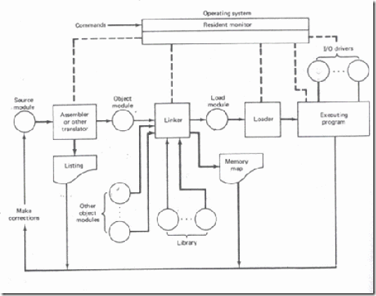
clip_image002

Figure 4.1 Creation and execution of a program

The DOS linking program links the different object modules of a source program and function library routines to generate an integrated executable code of the source program. The main input to the linker is the .OBJ file that contains the object modules of the source programs. Other supporting information may be obtained from the files generated by the MASM.

The linker program is invoked using the following options.

C> LINK

or

C>LINK MS.OBJ

The .OBJ extension is a must for a file to be accepted by the LINK as a valid object file. The first object may generate a display asking for the object file, list file and libraries as inputs and an expected name of the .EXE file to be generated. The output of the link program is an executable file with the entered filename and .EXE extension. This executable filename can further be entered at the DOS prompt to execute the file.

In the advanced version of the MASM, the complete procedure of assembling and linking is combined under a single menu invokable compile function. The recent versions of MASM have much more sophisticated and user-friendly facilities and options. A linker links the machine codes with the other required assembled codes. Linking is necessary because of the number of codes to be linked for the final binary file.

The linked file in binary for run on a computer is commonly known as executable file or simply ‘.exe.’ file. After linking, there has to be re-allocation of the sequences of placing the codes before actually placement of the codes in the memory. The loader program performs the task of reallocating the codes after finding the physical RAM addresses available at a given instant.

The DOS linking program links the different object modules of a source program and function library routines to generate an integrated executable code of the source program. The main input to the linker is the .OBJ file that contains the object modules of the source programs. Other supporting information may be obtained from the files generated by the MASM.

The linked file in binary for run on a computer is commonly known as executable file or simply ‘.exe.’ file. After linking, there has to be re-allocation of the sequences of placing the codes before actually placement of the codes in the memory. The loader program performs the task of reallocating the codes after finding the physical RAM addresses available at a given instant.

The loader is a part of the operating system and places codes into the memory after reading the ‘.exe’ file. This step is necessary because the available memory addresses may not start from 0x0000, and binary codes have to be loaded at the different addresses during the run. The loader finds the appropriate start address.

In a computer, the loader is used and it loads into a section of RAM the program that is ready to run. A program called locator reallocates the linked file and creates a file for permanent location of codes in a standard format.

4.1.1 Segment combination

In addition to the linker commands, the assembler provides a means of regulating the way segments in different object modules are organized by the linker. Segments with same name are joined together by using the modifiers attached to the SEGMENT directives. SEGMENT directive may have the form

Segment name                   SEGMENT                      Combination-type

where the combine-type indicates how the segment is to be located within the load module. Segments that have different names cannot be combined and segments with the same name but no combine-type will cause a linker error. The possible combine-types are:

PUBLIC – If the segments in different modules have the same name and combine-type PUBLIC, then they are concatenated into a single element in the load module. The ordering in the concatenation is specified by the linker command.

COMMON – If the segments in different object modules have the same name and the combine-type is COMMON, then they are overlaid so that they have the same starting address. The length of the common segment is that of the longest segment being overlaid.

STACK – If segments in different object modules have the same name and the combine- type STACK, then they become one segment whose length is the sum of the lengths of the individually specified segments. In effect, they are combined to form one large stack

AT – The AT combine-type is followed by an expression that evaluates to a constant which is to be the segment address. It allows the user to specify the exact location of the segment in memory.

MEMORY – This combine-type causes the segment to be placed at the last of the load module. If more than one segment with the MEMORY combine-type is being linked, only the first one will be treated as having the MEMORY combine type; the others will be overlaid as if they had COMMON combine-type.

image

image

image

4.1.2 Access to External Identifiers

If an identifier is defined in an object module, then it is said to be a local (or internal ) identifier relative to the module. If it is not defined in the module but is defined in one of the other modules being linked, then it is referred to as an external (or global) identifier relative to the module.In order to permit other object modules to reference some of the identifiers in a given module, the given module must include a list of the identifiers to which it will allow access. Therefore, each module in multi-module programs may contain two lists, one containing the external identifiers that can be referred to by other modules.

Two lists are implemented by the EXTRN and PUBLIC directives, which have the forms:

EXTRN Identifier: Type…, Identifier: Type

and

PUBLIC Identifier,…, Identifier

where the identifiers are the variables and labels being declared or as being available to other modules.

The assembler must know the type of all external identifiers before it can generate the proper machine code, a type specifier must be associated with each identifier in an EXTRN statement.

For a variable the type may be BYTE, WORD, or DWORD and for a label it may be NEAR or FAR.

One of the primary tasks of the linker is to verify that every identifier appearing in an EXTRN statement is matched by one in a PUBLIC statement. If this is not the case, then there will be an undefined reference and a linker error will occur.

The offsets for the local identifier will be inserted by the assembler, but the offsets for the external identifiers and all segment addresses must be inserted by the linking process.The offsets associated with all external references can be assigned once all of the object modules have been found and their external symbol tables have been examined.

The assignment of the segment addresses is called relocation and is done after the linking process has determined exactly where each segment is to be put in memory.

4.2 STACKS

The stack is a block of memory that may be used for temporarily storing the contents of the registers inside the CPU. It is a top-down data structure whose elements are accessed using the stack pointer (SP) which gets decremented by two as we store a data word into the stack and gets incremented by two as we retrieve a data word from the stack back to the CPU register.

The process of storing the data in the stack is called ‘pushing into’ the stack and the reverse process of transferring the data back from the stack to the CPU register is known as ‘popping off’ the stack. The stack is essentially Last-In-First-Out (LIFO) data segment. This means that the data which is pushed into the stack last will be on top of stack and will be popped off the stack first. The stack pointer is a 16-bit register that contains the offset address of the memory location in the stack segment.

The stack segment, like any other segment, may have a memory block of a maximum of 64 Kbytes locations, and thus may overlap with any other segments. Stack Segment register (SS) contains the base address of the stack segment in the memory.

The Stack Segment register (SS) and Stack pointer register (SP) together address the stack-top as explained below:

SS   clip_image007 5000H

SP clip_image0072050H

Physical address of Stack-top = 5000H * 10H + 2050H

If the stack top points to a memory location 52050H, it means that the location 52050H is already occupied with the previously pushed data. The next 16 bit push operation will decrement the stack pointer by two, so that it will point to the new stack-top 5204EH and the decremented contents of SP will be 204EH . This location will now be occupied by the recently pushed data.

image

Thus for a selected value of SS, the maximum value of SP=FFFFH and the segment can have maximum of 64K locations.

If the SP starts with an initial value of FFFFH, it will be decremented by two whenever a 16-bit data is pushed onto the stack. After successive push operations, when the stack pointer contains 0000H, any attempt to further push the data to the stack will result in stack overflow.

After a procedure is called using the CALL instruction, the IP is incremented to the next instruction. Then the contents of IP,CS and flag register are pushed automatically to the stack. The control is then transferred to the specified address in the CALL instruction i.e. starting address of the procedure. Then the procedure is executed.


Module3 8086 Microprocessor and Peripherals part1 .

ASSEMBLER DIRECTIVES AND OPERATORS

The main advantage of machine language programming is that the memory control is directly in the hands of the programmer, so that, he may be able to manage the memory of the system more efficiently. On the other hand, the disadvantages are more prominent. The programming, coding and resource management techniques are tedious. The programmer has to take care of these functions hence the chances of human errors are more. The programs are difficult to understand unless one has a thorough technical knowledge of the processor architecture and instruction set.

The assembly language programming is simpler as compared to the machine language programming. The instruction mnemonics are directly written in the assembly language programs. The programs are now more readable to users than the machine language programs. The main improvement in assembly language over machine language is that the address values and the constants can be identified by labels. If the labels are suggestive, then certainly the program will become more understandable, and each time the programmer will not have to remember the different constants and the addresses at which they are stored, throughout the programs. The labels may help to identify the addresses and con- stants. Due to this facility, the tedious byte handling and manipulations are got rid of. Similarly, now different logical segments and routines may be assigned with the labels rather than the different addresses. The memory control feature of machine language programming is left unchanged by providing storage define facilities in assembly language programming. The documentation facility which was not possible with machine language programming is now available in assembly language.

An assembler is a program used to convert an assembly language program into the equivalent machine code modules which may further be converted to executable codes. The assembler decides the address of each label and substitutes the values for each of the constants and variables. It then forms the machine code for the mnemonics and data in the assembly language program. While doing these things, the assembler may find out syntax errors. The logical errors or other programming errors are not found out by the assembler. For completing all these tasks, an assembler needs some hints from the programmer, i.e. the required storage for a particular constant or a variable, logical names of the segments, types of the different routines and modules, end of file, etc. These, types of hints are given to the assembler using some predefined alphabetical strings called assembler

directives. Assembler directives help the assembler to correctly understand the assembly language programs to prepare the codes.

Another type of hint which helps the assembler to assign a particular constant with a label or initialize particular memory locations or labels with constants is called an operator. Rather, the operators perform the arithmetic and logical tasks unlike directives that just direct the assembler to correctly interpret the program to code it appropriately. The following directives are commonly used in the assembly language programming practice using Microsoft Macro Assembler (MASM) or Turbo Assembler (TASM).

DB: Define Byte The DB directive is used to reserve byte or bytes of memory locations in the available memory. While preparing the EXE file, this directive directs the assembler to allocate the specified number of memory bytes to the said data type that may be a constant, variable, string, etc. Another option of this directive also initialises the reserved memory bytes with the ASCII codes of the characters specified as a string. The following examples show how the DB directive is used for different purposes.

Example:

LIST DB 0lH, 02H, 03H, 04H

This statement directs the assembler to reserve four memory locations for a list named LIST and initialise them with the above specified four values.

MESSAGE                  DB                    ‘GOOD MORNING’

This makes the assembler reserve the number of bytes of memory equal to the number of characters in the string named MESSAGE and initialise those locations by the ASCII equivalent of these characters.

VALUE               DB                 50H

This statement directs the assembler to reserve 50H memory bytes and leave them uninitialised for the variable named VALUE.

DW: Define Word. The DW directive serves the same purposes as the DB directive, but it now makes the assembler reserve the number of memory words (16-bit) instead of bytes. Some examples are given to explain this directive. Examples

WORDS DW 1234H, 4567H, 78ABH, 045CH

This makes the assembler reserve four words in memory (8 bytes), and initialize the words with the specified values in the statements. During initialisation, the lower bytes are stored at the lower memory addresses, while the upper bytes are stored at the higher addresses. Another option of the DW directive is explained with the DUP operator.

WDATA            DW 5 DUP (6666H)

This statement reserves five words, i.e. 10-bytes of memory for a word lable WDATA and initialises all the word locations with 6666H.

DQ: Define Quad word This directive is used to direct the assembler to reserve 4 words (8 bytes) of memory for the specified variable and may initialise it with the specified values.

DT: Define Ten Bytes. The DT directive directs the assembler to define the specified variable requiring la-bytes for its storage and initialise the 10bytes with the specified values. The directive may be used in case of variables facing heavy numerical calculations, generally processed by numerical processors.

ASSUME: Assume Logical Segment Name The ASSUME directive is used to inform the assemble, the names of the logical segments to be assumed for different segments used in the program. In the assembly language program, each segment is given a name. For example, the code segment may be given the name CODE, data segment may be given the name DATA etc. The statement ASSUME CS : CODE directs the assembler that the machine codes are available in a segment named CODE, and hence the CS register is to be loaded with the address (segment) allotted by the operating system for the label CODE, while loading. Similarly, ASSUME DS : DATA indicates to the assembler that the data items related to the program, are available in a logical segment named DATA, and the DS register is to be initialised by the segment address value decided by the operating system for the data segment, while loading. It then considers the segment DATA as a default data segment for each memory operation, related to the data and the segment CODE as a source segment for the machine codes of the program. The ASSUME statement is a must at the starting of each assembly language program,

END: END of Program The END directive marks the end of an assembly language program. When the assembler comes across this END directive, it ignores the source lines available later on. Hence, it should be ensured that the END statement should be the last statement in the file and should not appear in between. Also, no useful program statement should lie in the file, after the END statement

ENDP: END of Procedure. In assembly language programming, the subroutines are called procedures. Thus, procedures may be independent program modules which return particular results or values to the calling programs. The ENDP directive is used to indicate the end of a procedure. A procedure is usually

assigned a name, i.e. label. To mark the end of a particular procedure, the name of the procedure, i.e. label may appear as a prefix with the directive ENDP. The statements, appearing in the same module but after the ENDP directive, are neglected from that procedure. The structure given below explains the use of ENDP.

image

ENDS: END of Segment This directive marks the end of a logical segment. The logical segments are assigned with the names using the ASSUME directive. The names appear with the ENDS directive as prefixes to mark the end of those particular segments. Whatever are the contents of the segments, they should appear in the program before ENDS. Any statement appearing after ENDS will be neglected from the segment. The structure shown below explains the fact more clearly.

image

The above structure represents a simple program containing two segments named DATA and CODE. The data related to the program must lie between the DATA SEGMENT and DATA ENDS statements. Similarly, all the executable instructions must lie between CODE SEGMENT and CODE ENDS statements.

EVEN: Align on Even Memory Address The assembler, while starting the assembling procedure of any program, initialises a location counter and goes on updating it, as the assembly proceeds. It goes on assigning the available addresses, i.e. the contents of the location counter, sequentially to the program variables,

constants and modules as per their requirements, in the sequence in which they appear in the program. The EVEN directive updates the location counter to the next even address if the current location counter contents are not even, and assigns the following routine or variable or constant to that address. The structure given below explains the directive.

image

The above structure shows a procedure ROOT that is to be aligned at an even address. The assembler will start assembling the main program calling ROOT. When the assembler comes across the directive EVEN, it checks the contents of the location counter. If it is odd, it is updated to the next even value and then the ROOT procedure is assigned to that address, i.e. the updated contents of the location counter. If the content of the location counter is already even, then the ROOT procedure will be assigned with the same address.

EQU: Equate The directive EQU is used to assign a label with a value or a symbol. The use of this directive is just to reduce the recurrence of the numerical values or constants in a program code. The recurring value is assigned with a label, and that label is used in place of that numerical value, throughout the program. While assembling, whenever the assembler comes across the label, it substitutes the numerical value for that label and finds out the equivalent code. Using the EQU directive, even an instruction mnemonic can be assigned with a label, and the label can then be used in the program in place of that mnemonic.

Suppose, a numerical constant appears ‘in a program ten times. If that constant is to be changed at a later time, one will have to make all these ten corrections. This may lead to human errors, because it is possible that a human programmer may miss one of those corrections. This will result in the generation of wrong codes. If the EQU directive is used to assign the value with a label that can be used in place of each recurrence of that constant, only one change in the EQU statement will give the correct and modified code. The examples given below show the syntax.

Example

LABEL           EQU              0500H

ADDITION EQU           ADD

The first statement assigns the constant 500H with the label LABEL, while the second statement assigns another label ADDITION with mnemonic ADD.

EXTRN: External and PUBLIC: Public The directive EXTRN informs the assembler that the names, procedures and labels declared after this directive have already been defined in some other assembly language modules. While in the other module, where the names, procedures and labels actually appear, they must be declared public, using the PUBLIC directive. If one wants to call a procedure FACTORIAL appearing in MODULE 1 from MODULE 2; in MODULE1, it must be declared PUBLIC using the statement PUBLIC FACTORIAL and in module 2, it must be declared external using the declaration EXTRN FACTORIAL. The statement of declaration EXTRN must be accompained by the SEGMENT and ENDS directives of the MODULE 1, before it is called in MOBULE 2. Thus the MODULE 1 and MODULE 2 must have the following declarations.

image

GROUP: Group the Related segment The directive is used to form logical groups of segments with similar purpose or type. This directive is used to inform the assembler to form a logical group of the following segment names. The assembler passes an information to the linker/loader to form the code such that the group declared segments or operands must lie within a 64Kbyte memory segment. Thus all such segments and labels can be addressed using the same segment base.

PROGRAM GROUP CODE, DATA, STACK

The above statement directs the loader/linker to prepare an EXE file such that CODE, DATA and STACK segment must lie within a 64kbyte memory segment that is named as PROGRAM. Now, for the ASSUME statement, one can use the label PROGRAM rather than CODE, DATA and STACK as shown.


Module2 8086 Microprocessor and Peripherals part3.

Data Transfer Instructions :

The MOV instruction is used to transfer a byte or a word of data from a source operand to a destination operand. These operands can be internal registers of the 8086 and storage locations in memory.

image

image

MOV instruction cannot transfer data directly between a source and a destination that both reside in external memory.

INPUT/OUTPUT INSTRUCTIONS :

IN acc, port : In transfers a byte or a word from input port to the AL register or the AX register respectively. The port number my be specified either with an immediate byte constant, allowing access to ports numbered 0 through 255 or with a number previously placed in the DX register allowing variable access (by changing the value in DX) to ports numbered from 0 through 65,535.

image

OUT port, acc : Out transfers a byte or a word from the AL register or the AX register respectively to an output port. The port numbers may be specified either with an immediate byte or with a number previously placed in the register DX allowing variable access.

No flags are affected.

image

image

XLAT (translate):

This instruction is useful for translating characters from one code such as ASCII to another such as EBCDIC, this is no operand instruction and is called an instruction with implied addressing mode.

The instruction loads AL with the contents of a 20 bit physical address computed from DS, BX and AL. This instruction can be used to read the elements in a table where BX can be loaded with a 16 bit value to point to the starting address (offset from DS) and AL can be loaded with the element number (0 being the first element number) no flags are affected.

XLAT instruction is equivalent to

MOV AL, [AL] [BX]

AL ← [(AL) + (BX) + (DS)]

Example :

Write a program to convert binary to gray code for the numbers 0 to F using translate instruction.

Let the binary number is stored at 0350 and its equivalent gray code is stored at 0351 after the program execution. Look up table is as follows.

image

The first two instructions LAHF and SAHF can be used either to read the flags or to change them respectively notice that the data transfer that takes place is always between the AH register and flag register. For instance, we may want to start an operation with certain flags set or reset. Assume that we want to preset all flags to logic 1. To do this we can first load AH with FF and then execute the SAHF instruction.

Example : Write an instruction sequence to save the contents of the 8086’s flags in memory location MEM1 and then reload the flags with the contents of memory location MEM2. Assume that MEM1 and MEM2 are in the same data segment defined by the current contents of DS.

image

Strings and String Handling Instructions :

The 8086 microprocessor is equipped with special instructions to handle string operations. By string we mean a series of data words or bytes that reside in consecutive memory locations. The string instructions of the 8086 permit a programmer to implement operations such as to move data from one block of memory to a block elsewhere in memory. A second type of operation that is easily performed is to scan a string and data elements stored in memory looking for a specific value. Other examples are to compare the elements and two strings together in order to determine whether they are the same or different.

Move String : MOV SB, MOV SW:

An element of the string specified by the source index (SI) register with respect to the current data segment (DS) register is moved to the location specified by the destination index (DI) register with respect to the current extra segment (ES) register.

The move can be performed on a byte (MOV SB) or a word (MOV SW) of data. After the move is complete, the contents of both SI & DI are automatically incremented or decremented by 1 for a byte move and by 2 for a word move. Address pointers SI and DI increment or decrement depends on how the direction flag DF is set.

Example : Block move program using the move string instruction

image

image

Load and store strings : (LOD SB/LOD SW and STO SB/STO SW)

LOD SB: Loads a byte from a string in memory into AL. The address in SI is used relative to DS to determine the address of the memory location of the string element.

(AL) ← [(DS) + (SI)]

(SI) ← (SI) + 1

LOD SW : The word string element at the physical address derived from DS and SI is to be loaded into AX. SI is automatically incremented by 2.

(AX) ← [(DS) + (SI)]

(SI) ← (SI) + 2

STO SB : Stores a byte from AL into a string location in memory. This time the contents of ES and DI are used to form the address of the storage location in memory

image

image

Repeat String : REP

The basic string operations must be repeated to process arrays of data. This is done by inserting a repeat prefix before the instruction that is to be repeated.

Prefix REP causes the basic string operation to be repeated until the contents of register CX become equal to zero. Each time the instruction is executed, it causes CX

to be tested for zero, if CX is found to be nonzero it is decremented by 1 and the basic string operation is repeated.

Example : Clearing a block of memory by repeating STOSB

image

The prefixes REPE and REPZ stand for same function. They are meant for use with the CMPS and SCAS instructions. With REPE/REPZ the basic compare or scan operation

can be repeated as long as both the contents of CX are not equal to zero and zero flag is 1.

REPNE and REPNZ works similarly to REPE/REPZ except that now the operation is repeated as long as CX≠0 and ZF=0. Comparison or scanning is to be performed as long as the string elements are unequal (ZF=0) and the end of the string is not yet found (CX≠0).

image

Moves a block of 32 consecutive bytes from the block of memory locations starting at offset address MASTER with respect to the current data segment (DS) to a block of locations starting at offset address copy with respect to the current extra segment (ES).

Auto Indexing for String Instructions :

SI & DI addresses are either automatically incremented or decremented based on the setting of the direction flag DF.

When CLD (Clear Direction Flag) is executed DF=0 permits auto increment by 1. When STD (Set Direction Flag) is executed DF=1 permits auto decrement by 1.

image

1. LDS Instruction:

LDS register, memory (Loads register and DS with words from memory)

This instruction copies a word from two memory locations into the register specified in the instruction. It then copies a word from the next two memory locations into the DS register. LDS is useful for pointing SI and DS at the start of the string before using one of the string instructions. LDS affects no flags.

Example 1 :LDS BX [1234]

Copy contents of memory at displacement 1234 in DS to BL. Contents of 1235H to BH. Copy contents at displacement of 1236H and 1237H is DS to DS register.

image

2. LEA Instruction :

Load Effective Address (LEA register, source)

This instruction determines the offset of the variable or memory location named as the source and puts this offset in the indicated 16 bit register.

image

image


Module2 8086 Microprocessor and Peripherals part2 .

String Manipulation Instructions

A series of data byte or word available in memory at consecutive locations, to be referred as Byte String or Word String. A String of characters may be located in consecutive memory locations, where each character may be represented by its ASCII equivalent.

The 8086 supports a set of more powerful instructions for string manipulations for referring to a string, two parameters are required.

I. Starting and End Address of the String.

II. Length of the String.

The length of the string is usually stored as count in the CX register.The incrementing or decrementing of the pointer, in string instructions, depends upon the Direction Flag (DF) Status. If it is a Byte string operation, the index registers are updated by one. On the other hand, if it is a word string operation, the index registers are updated by two.

REP : Repeat Instruction Prefix

This instruction is used as a prefix to other instructions, the instruction to which the REP prefix is provided, is executed repeatedly until the CX register becomes zero (at each iteration CX is automatically decremented by one).

i. REPE / REPZ – repeat operation while equal / zero.

ii. REPNE / REPNZ – repeat operation while not equal / not zero.

These are used for CMPS, SCAS instructions only, as instruction prefixes.

MOVSB / MOVSW :Move String Byte or String Word

Suppose a string of bytes stored in a set of consecutive memory locations is to be moved to another set of destination locations.The starting byte of source string is located in the memory location whose address may be computed using SI (Source Index) and DS (Data Segment) contents.

The starting address of the destination locations where this string has to be relocated is given by DI (Destination Index) and ES (Extra Segment) contents.

CMPS : Compare String Byte or String Word

The CMPS instruction can be used to compare two strings of byte or words. The length of the string must be stored in the register CX. If both the byte or word strings are equal, zero Flag is set.

The REP instruction Prefix is used to repeat the operation till CX (counter) becomes zero or the condition specified by the REP Prefix is False.

SCAN : Scan String Byte or String Word

This instruction scans a string of bytes or words for an operand byte or word specified in the register AL or AX. The String is pointed to by ES:DI register pair. The length of the string s stored in CX. The DF controls the mode for scanning of the string. Whenever a match to the specified operand, is found in the string, execution stops and the zero Flag is set. If no match is found, the zero flag is reset.

LODS : Load String Byte or String Word

The LODS instruction loads the AL / AX register by the content of a string pointed to by DS : SI register pair. The SI is modified automatically depending upon DF, If it is a byte transfer (LODSB), the SI is modified by one and if it is a word transfer (LODSW), the SI is modified by two. No other Flags are affected by this instruction.

STOS : Store String Byte or String Word

The STOS instruction Stores the AL / AX register contents to a location in the string pointer by ES : DI register pair. The DI is modified accordingly, No Flags are affected by this instruction.

The direction Flag controls the String instruction execution, The source index SI and Destination Index DI are modified after each iteration automatically. If DF=1, then the execution follows autodecrement mode, SI and DI are decremented automatically after each iteration. If DF=0, then the execution follows autoincrement mode. In this mode, SI and DI are incremented automatically after each iteration.

Flag Manipulation and a Processor Control Instructions

These instructions control the functioning of the available hardware inside the processor chip. These instructions are categorized into two types:

1. Flag Manipulation instructions.

2. Machine Control instructions.

Flag Manipulation instructions

The Flag manipulation instructions directly modify some of the Flags of 8086.

i. CLC – Clear Carry Flag.

ii. CMC – Complement Carry Flag.

iii. STC – Set Carry Flag.

iv. CLD – Clear Direction Flag.

v. STD – Set Direction Flag.

vi. CLI – Clear Interrupt Flag.

vii. STI – Set Interrupt Flag.

Machine Control instructions

The Machine control instructions control the bus usage and execution

i. WAIT – Wait for Test input pin to go low.

ii. HLT – Halt the process.

iii. NOP – No operation.

iv. ESC – Escape to external device like NDP

v. LOCK – Bus lock instruction prefix.

Addressing Modes

Addressing modes of 8086

When 8086 executes an instruction, it performs the specified function on data. These data are called its operands and may be part of the instruction, reside in one of the internal registers of the microprocessor, stored at an address in memory or held at an I/O port, to access these different types of operands, the 8086 is provided with various addressing modes (Data Addressing Modes).

Data Addressing Modes of 8086

The 8086 has 12 addressing modes. The various 8086 addressing modes can be classified into five groups.

A. Addressing modes for accessing immediate and register data (register and immediate modes).

B. Addressing modes for accessing data in memory (memory modes)

C. Addressing modes for accessing I/O ports (I/O modes)

D. Relative addressing mode

E. Implied addressing mode

8086 ADDRESSING MODES

A. Immediate addressing mode:

In this mode, 8 or 16 bit data can be specified as part of the instruction.

image

Register addressing mode :

The operand to be accessed is specified as residing in an internal register of 8086. Fig.

below shows internal registers, any one can be used as a source or destination operand, however only the data registers can be accessed as either a byte or word.

image

B. Direct addressing mode :

The instruction Opcode is followed by an affective address, this effective address is directly used as the 16 bit offset of the storage location of the operand from the location specified by the current value in the selected segment register.

The default segment is always DS.

The 20 bit physical address of the operand in memory is normally obtained as

PA = DS : EA

But by using a segment override prefix (SOP) in the instruction, any of the four segment registers can be referenced,

image

The Execution Unit (EU) has direct access to all registers and data for register and immediate operands. However the EU cannot directly access the memory operands. It must use the BIU, in order to access memory operands.

In the direct addressing mode, the 16 bit effective address (EA) is taken directly from the displacement field of the instruction.

Example 1 : MOV CX, START

If the 16 bit value assigned to the offset START by the programmer using an assembler pseudo instruction such as DW is 0040 and [DS] = 3050. Then BIU generates the 20 bit physical address 30540 H.

The content of 30540 is moved to CL The content of 30541 is moved to CH

Example 2 : MOV CH, START

If [DS] = 3050 and START = 0040

8 bit content of memory location 30540 is moved to CH.

Example 3 : MOV START, BX

With [DS] = 3050, the value of START is 0040.

Physical address : 30540

MOV instruction moves (BL) and (BH) to locations 30540 and 30541 respectively.

Register indirect addressing mode :

The EA is specified in either pointer (BX) register or an index (SI or DI) register. The 20 bit physical address is computed using DS and EA.

image

image

String addressing mode:

The string instructions automatically assume SI to point to the first byte or word of the source operand and DI to point to the first byte or word of the destination operand. The contents of SI and DI are automatically incremented (by clearing DF to 0 by CLD instruction) to point to the next byte or word.

image

If [DX] = 5040

8 bit content by port 5040 is moved into AL.

Example 2 :                   IN AX, DX

Inputs 8 bit content of ports 5040 and 5041 into AL and AH respectively.

D. Relative addressing mode:

Example : JNC START

If CY=O, then PC is loaded with current PC contents plus 8 bit signed value of START, otherwise the next instruction is executed.

E. Implied addressing mode:

Instruction using this mode have no operands.

Example : CLC which clears carry flag to zero.

image

Special functions of general-purpose registers: AX & DX registers:

In 8 bit multiplication, one of the operands must be in AL. The other operand can be a byte in memory location or in another 8 bit register. The resulting 16 bit product is stored in AX, with AH storing the MS byte.

In 16 bit multiplication, one of the operands must be in AX. The other operand can be a word in memory location or in another 16 bit register. The resulting 32 bit product is stored in DX and AX, with DX storing the MS word and AX storing the LS word.

BX register : In instructions where we need to specify in a general purpose register the 16 bit effective address of a memory location, the register BX is used (register indirect).

CX register : In Loop Instructions, CX register will be always used as the implied counter.

In I/O instructions, the 8086 receives into or sends out data from AX or AL depending as a word or byte operation. In these instructions the port address, if greater than FFH has to be given as the contents of DX register.

Ex : IN AL, DX

DX register will have 16 bit address of the I/P device

Physical Address (PA) generation :

Generally Physical Address (20 Bit) = Segment Base Address (SBA)

image

Instruction Format :

The 8086 instruction sizes vary from one to six bytes. The OP code occupies six bytes and it defines the operation to be carried out by the instruction.

Register Direct bit (D) occupies one bit. It defines whether the register operand in byte 2 is the source or destination operand.

D=1 Specifies that the register operand is the destination operand.

D=0 indicates that the register is a source operand.

Data size bit (W) defines whether the operation to be performed is an 8 bit or 16 bit data

W=0 indicates 8 bit operation

W=1 indicates 16 bit operation

image

The second byte of the instruction usually identifies whether one of the operands is in memory or whether both are registers.

This byte contains 3 fields. These are the mode (MOD) field, the register (REG) field and the Register/Memory (R/M) field.

image

Register field occupies 3 bits. It defines the register for the first operand which is specified as source or destination by the D bit.

image

In the above, encoding of the R/M field depends on how the mode field is set. If MOD=11 (register to register mode), this R/M identifies the second register operand.

MOD selects memory mode, then R/M indicates how the effective address of the memory operand is to be calculated. Bytes 3 through 6 of an instruction are optional fields that normally contain the displacement value of a memory operand and / or the actual value of an immediate constant operand.

Example 1 : MOV CH, BL

This instruction transfers 8 bit content of BL

Into CH

The 6 bit Opcode for this instruction is 1000102 D bit indicates whether the register specified by the REG field of byte 2 is a source or destination operand.

D=0 indicates BL is a source operand.

W=0 byte operation

In byte 2, since the second operand is a register MOD field is 112.

The R/M field = 101 (CH)

Register (REG) field = 011 (BL)

Hence the machine code for MOV CH, BL is

10001000 11 011 101

Byte 1 Byte2

= 88DD16

Example 2 : SUB Bx, (DI)

This instruction subtracts the 16 bit content of memory location addressed by DI and DS from Bx. The 6 bit Opcode for SUB is 0010102.

D=1 so that REG field of byte 2 is the destination operand. W=1 indicates 16 bit operation.

MOD = 00

REG = 011

R/M = 101

image

Summary of all Addressing Modes

Example 3 : Code for MOV 1234 (BP), DX

Here we have specify DX using REG field, the D bit must be 0, indicating the DX is the source register. The REG field must be 010 to indicate DX register. The W bit must be 1 to indicate it is a word operation. 1234 [BP] is specified using MOD value of 10 and R/M value of 110 and a displacement of 1234H. The 4 byte code for this instruction would be 89 96 34 12H.

image

Example 4 : Code for MOV DS : 2345 [BP], DX

Here we have to specify DX using REG field. The D bit must be o, indicating that Dx is the source register. The REG field must be 010 to indicate DX register. The w bit must be 1 to indicate it is a word operation. 2345 [BP] is specified with MOD=10 and R/M = 110 and displacement = 2345 H.

Whenever BP is used to generate the Effective Address (EA), the default segment would be SS. In this example, we want the segment register to be DS, we have to provide the segment override prefix byte (SOP byte) to start with. The SOP byte is 001 SR 110, where SR value is provided as per table shown below.

image

Example 5 :

Give the instruction template and generate code for the instruction ADD OFABE [BX], [DI], DX (code for ADD instruction is 000000)

ADD OFABE [BX] [DI], DX

Here we have to specify DX using REG field. The bit D is 0, indicating that DX is the source register. The REG field must be 010 to indicate DX register. The w must be 1 to indicate it is a word operation. FABE (BX + DI) is specified using MOD value of 10 and R/M value of 001 (from the summary table). The 4 byte code for this instruction would be

image

Example 6 :

Give the instruction template and generate the code for the instruction MOV AX, [BX]

(Code for MOV instruction is 100010)

AX destination register with D=1 and code for AX is 000 [BX] is specified using 00 Mode and R/M value 111

It is a word operation

image

Questions :

1. Write a note on segment registers.

2. List the rules for segmentation.

3. What are the advantages of using segmentation?

4. What do you mean by index registers?

5. What is the function of SI and DI registers?

6. Explain the addressing modes of 8086 with the help of examples.

7. What do you mean by segment override prefix?

8. Write a short notes on i) Instruction formats ii) Instruction execution timing

9. Determine and explain the addressing modes of the following 8086 instructions.

i) PUSH BX ii) CALL BX iii) JMP DWORD PTR 6200 [BX]

iv) OR OABCD [BX] [SI], CX v) INT O

10. Give the instruction template and generate code for the instruction ADD OFABE [BX] [DI], DX (code for ADD instruction is 000 000)

11. Explain the special functions performed by general purpose registers of 8086.

12. Give the instruction template and generate the code for the instruction MOV AX, [BX].


Module2 8086 Microprocessor and Peripherals part1 .

2.1 Read Write Timing Diagram

General Bus Operation

The 8086 has a combined address and data bus commonly referred as a time multiplexed address and data bus. The main reason behind multiplexing address and data over the same pins is the maximum utilization of processor pins and it facilitates the use of 40 pin standard DIP package. The bus can be demultiplexed using a few latches and transreceivers, whenever required.

Basically, all the processor bus cycles consist of at least four clock cycles. These are referred to as T1, T2, T3, T4. The address is transmitted by the processor during T1, It is present on the bus only for one cycle. The negative edge of this ALE pulse is used to separate the address and the data or status information.

In maximum mode, the status lines S0, S1 and S2 are used to indicate the type of operation. Status bits S3 to S7 are multiplexed with higher order address bits and the BHE signal. Address is valid during T1 while status bits S3 to S7 are valid during T2 through T4.

clip_image002

Fig. 2.1 General Bus Operation Cycle of 8086

Maximum Mode

i. In the maximum mode, the 8086 is operated by strapping the MN/MX pin to ground.

ii. In this mode, the processor derives the status signal S2, S1, S0. Another chip called bus controller derives the control signal using this status information.

iii. In the maximum mode, there may be more than one microprocessor in the system configuration.

Minimum Mode

i. In a minimum mode 8086 system, the microprocessor 8086 is operated in minimum mode by strapping its MN/MX pin to logic 1.

ii. In this mode, all the control signals are given out by the microprocessor chip itself.

2.2 Instruction Set of 8086

The 8086 instructions are categorized into the following main types.

i. Data Copy / Transfer Instructions

ii. Arithmetic and Logical Instructions

iii. Branch Instructions

iv. Loop Instructions

v. Machine Control Instructions

vi. Flag Manipulation Instructions

vii. Shift and Rotate Instructions

viii. String Instructions

Data Copy / Transfer Instructions :

MOV :

This instruction copies a word or a byte of data from some source to a destination. The destination can be a register or a memory location. The source can be a register, a memory location, or an immediate number.

MOV AX,BX

MOV AX,5000H

MOV AX,[SI]

MOV AX,[2000H]

MOV AX,50H[BX]

MOV [734AH],BX

MOV DS,CX

MOV CL,[357AH]

Direct loading of the segment registers with immediate data is not permitted.

PUSH : Push to Stack

This instruction pushes the contents of the specified register/memory location on to the stack. The stack pointer is decremented by 2, after each execution of the instruction.

E.g. PUSH AX

• PUSH DS

• PUSH [5000H]clip_image004

Fig. 2.2 Push Data to stack memory
POP : Pop from Sack

This instruction when executed, loads the specified register/memory location with the contents of the memory location of which the address is formed using the current stack segment and stack pointer.

The stack pointer is incremented by 2

Eg. POP AX

POP DS

POP [5000H]

clip_image006

Fig 2.3 Popping Register Content from Stack Memory
XCHG : Exchange byte or word

This instruction exchange the contents of the specified source and destination operands

Eg. XCHG [5000H], AX

XCHG BX, AX

XLAT :

Translate byte using look-up table

Eg. LEA BX, TABLE1

MOV AL, 04H

XLAT

Simple input and output port transfer Instructions:

IN:

Copy a byte or word from specified port to accumulator.

Eg. IN AL,03H

IN AX,DX

OUT:

Copy a byte or word from accumulator specified port.

Eg. OUT 03H, AL

OUT DX, AX

LEA :

Load effective address of operand in specified register.

[reg] offset portion of address in DS

Eg. LEA reg, offset

LDS:

Load DS register and other specified register from memory.

[reg] [mem]

[DS] [mem + 2]

Eg. LDS reg, mem

LES:

Load ES register and other specified register from memory.

[reg] [mem]

[ES] [mem + 2]

Eg. LES reg, mem

Flag transfer instructions:

LAHF:

image

image

Arithmetic Instructions:

The 8086 provides many arithmetic operations: addition, subtraction, negation, multiplication and comparing two values.

ADD :

The add instruction adds the contents of the source operand to the destination operand.

Eg. ADD AX, 0100H

ADD AX, BX

ADD AX, [SI]

ADD AX, [5000H]

ADD [5000H], 0100H

ADD 0100H

ADC : Add with Carry

This instruction performs the same operation as ADD instruction, but adds the carry flag to the result.

Eg. ADC 0100H

ADC AX, BX

ADC AX, [SI]

ADC AX, [5000]

ADC [5000], 0100H

SUB : Subtract

The subtract instruction subtracts the source operand from the destination operand and the result is left in the destination operand.

Eg. SUB AX, 0100H

SUB AX, BX

SUB AX, [5000H]

SUB [5000H], 0100H

SBB : Subtract with Borrow

The subtract with borrow instruction subtracts the source operand and the borrow flag (CF) which may reflect the result of the previous calculations, from the destination operand

Eg. SBB AX, 0100H

SBB AX, BX

SBB AX, [5000H]

SBB [5000H], 0100H

INC : Increment

This instruction increases the contents of the specified Register or memory location by 1. Immediate data cannot be operand of this instruction.

Eg. INC AX

INC [BX]

INC [5000H]

DEC : Decrement

The decrement instruction subtracts 1 from the contents of the specified register or memory location.

Eg. DEC AX

DEC [5000H]

NEG : Negate

The negate instruction forms 2’s complement of the specified destination in the instruction. The destination can be a register or a memory location. This instruction can be implemented by inverting each bit and adding 1 to it.

Eg. NEG AL

AL = 0011 0101 35H Replace number in AL with its 2’s complement

AL = 1100 1011 = CBH

CMP : Compare

This instruction compares the source operand, which may be a register or an immediate data or a memory location, with a destination operand that may be a register or a memory location

Eg. CMP BX, 0100H

CMP AX, 0100H

CMP [5000H], 0100H

CMP BX, [SI]

CMP BX, CX

MUL :Unsigned Multiplication Byte or Word

This instruction multiplies an unsigned byte or word by the contents of AL.

Eg. MUL BH

; (AX)

(AL) x (BH)

MUL CX

MUL WORD PT

; (DX)(AX)

R [SI] ; (DX)(AX)

(AX) x (CX)

(AX) x ([SI])

IMUL :Signed Multiplication

This instruction multiplies a signed byte in source operand by a signed byte in AL or a signed word in source operand by a signed word in AX.

Eg. IMUL BH

IMUL CX

IMUL [SI]

CBW : Convert Signed Byte to Word

This instruction copies the sign of a byte in AL to all the bits in AH. AH is then said to be sign extension of AL.

Eg. CBW

AX= 0000 0000 1001 1000 Convert signed byte in AL signed word in AX.

Result in AX = 1111 1111 1001 1000

CWD : Convert Signed Word to Double Word

This instruction copies the sign of a byte in AL to all the bits in AH. AH is then said to be sign extension of AL.

Eg. CWD

Convert signed word in AX to signed double word in DX : AX

DX= 1111 1111 1111 1111

Result in AX = 1111 0000 1100 0001

DIV : Unsigned division

This instruction is used to divide an unsigned word by a byte or to divide an unsigned double word by a word.

image

AAA : ASCII Adjust After Addition

The AAA instruction is executed aftr an ADD instruction that adds two ASCII coded operand to give a byte of result in AL. The AAA instruction converts the resulting contents of Al to a unpacked decimal digits.

image

AAS : ASCII Adjust AL after Subtraction

This instruction corrects the result in AL register after subtracting two unpacked ASCII operands. The result is in unpacked decimal format. The procedure is similar to AAA instruction except for the subtraction of 06 from AL.

AAM : ASCII Adjust after Multiplication

This instruction, after execution, converts the product available In AL into unpacked BCD format.

image

AAD : ASCII Adjust before Division

This instruction converts two unpacked BCD digits in AH and AL to the equivalent binary number in AL. This adjustment must be made before dividing the two unpacked BCD digits in AX by an unpacked BCD byte. In the instruction sequence, this instruction appears Before DIV instruction.

image

DAS : Decimal Adjust after Subtraction

This instruction converts the result of the subtraction of two packed BCD numbers to a valid BCD number. The subtraction has to be in AL only.

image

Logical Instructions

AND : Logical AND

This instruction bit by bit ANDs the source operand that may be an immediate register or a memory location to the destination operand that may a register or a memory location. The result is stored in the destination operand.

Eg. AND AX, 0008H

AND AX, BX

OR : Logical OR

This instruction bit by bit ORs the source operand that may be an immediate , register or a memory location to the destination operand that may a register or a memory location. The result is stored in the destination operand.

Eg. OR AX, 0008H

OR AX, BX

NOT : Logical Invert

This instruction complements the contents of an operand register or a memory location, bit by bit.

Eg. NOT AX

NOT [5000H]

XOR : Logical Exclusive OR

This instruction bit by bit XORs the source operand that may be an immediate , register or a memory location to the destination operand that may a register or a memory location. The result is stored in the destination operand.

Eg. XOR AX, 0098H

XOR AX, BX

TEST : Logical Compare Instruction

The TEST instruction performs a bit by bit logical AND operation on the two operands. The result of this ANDing operation is not available for further use, but flags are affected.

image

SAL/SHL : SAL / SHL destination, count.

SAL and SHL are two mnemonics for the same instruction. This instruction shifts each bit in the specified destination to the left and 0 is stored at LSB position. The MSB is shifted into the carry flag. The destination can be a byte or a word.

It can be in a register or in a memory location. The number of shifts is indicated by count.

Eg. SAL CX, 1

SAL AX, CL

SHR : SHR destination, count

This instruction shifts each bit in the specified destination to the right and 0 is stored at MSB position. The LSB is shifted into the carry flag. The destination can be a byte or a word.

It can be a register or in a memory location. The number of shifts is indicated by count.

Eg. SHR CX, 1

MOV CL, 05H

SHR AX, CL

SAR : SAR destination, count

This instruction shifts each bit in the specified destination some number of bit positions to the right. As a bit is shifted out of the MSB position, a copy of the old MSB is put in the MSB position. The LSB will be shifted into CF.

Eg. SAR BL, 1

MOV CL, 04H

SAR DX, CL

ROL Instruction : ROL destination, count

This instruction rotates all bits in a specified byte or word to the left some number of bit positions. MSB is placed as a new LSB and a new CF.

Eg. ROL CX, 1

MOV CL, 03H

ROL BL, CL

ROR Instruction : ROR destination, count

This instruction rotates all bits in a specified byte or word to the right some number of bit positions. LSB is placed as a new MSB and a new CF.

Eg. ROR CX, 1

MOV CL, 03H

ROR BL, CL

RCL Instruction : RCL destination, count

This instruction rotates all bits in a specified byte or word some number of bit positions to the left along with the carry flag. MSB is placed as a new carry and previous carry is place as new LSB.

Eg. RCL CX, 1

MOV CL, 04H

RCL AL, CL

RCR Instruction : RCR destination, count

This instruction rotates all bits in a specified byte or word some number of bit positions to the right along with the carry flag. LSB is placed as a new carry and previous carry is place as new MSB.

Eg. RCR CX, 1

MOV CL, 04H

RCR AL, CL

Branch Instructions :

Branch Instructions transfers the flow of execution of the program to a new address specified in the instruction directly or indirectly. When this type of instruction is executed, the CS and IP registers get loaded with new values of CS and IP corresponding to the location to be transferred.

The Branch Instructions are classified into two types

i. Unconditional Branch Instructions.

ii. Conditional Branch Instructions.

Unconditional Branch Instructions :

In Unconditional control transfer instructions, the execution control is transferred to the specified location independent of any status or condition. The CS and IP are unconditionally modified to the new CS and IP.

CALL : Unconditional Call

This instruction is used to call a Subroutine (Procedure) from a main program. Address of procedure may be specified directly or indirectly.

There are two types of procedure depending upon whether it is available in the same segment or in another segment.

i. Near CALL i.e., ±32K displacement.

ii. For CALL i.e., anywhere outside the segment.

On execution this instruction stores the incremented IP & CS onto the stack and loads the CS & IP registers with segment and offset addresses of the procedure to be called.

RET: Return from the Procedure.

At the end of the procedure, the RET instruction must be executed. When it is executed, the previously stored content of IP and CS along with Flags are retrieved into the CS, IP and Flag registers from the stack and execution of the main program continues further.

INT N: Interrupt Type N.

In the interrupt structure of 8086, 256 interrupts are defined corresponding to the types from 00H to FFH. When INT N instruction is executed, the type byte N is multiplied by 4 and the contents of IP and CS of the interrupt service routine will be taken from memory block in 0000 segment.

INTO: Interrupt on Overflow

This instruction is executed, when the overflow flag OF is set. This is equivalent to a Type 4 Interrupt instruction.

JMP: Unconditional Jump

This instruction unconditionally transfers the control of execution to the specified address using an 8-bit or 16-bit displacement. No Flags are affected by this instruction.

IRET: Return from ISR

When it is executed, the values of IP, CS and Flags are retrieved from the stack to continue the execution of the main program.

LOOP : LOOP Unconditionally

This instruction executes the part of the program from the Label or address specified in the instruction upto the LOOP instruction CX number of times. At each iteration, CX is decremented automatically and JUMP IF NOT ZERO structure.

image

Conditional Branch Instructions

When this instruction is executed, execution control is transferred to the address specified relatively in the instruction, provided the condition implicit in the Opcode is satisfied. Otherwise execution continues sequentially.

JZ/JE Label

Transfer execution control to address ‘Label’, if ZF=1.

JNZ/JNE Label

Transfer execution control to address ‘Label’, if ZF=0

JS Label

Transfer execution control to address ‘Label’, if SF=1.

JNS Label

Transfer execution control to address ‘Label’, if SF=0.

JO Label

Transfer execution control to address ‘Label’, if OF=1.

JNO Label

Transfer execution control to address ‘Label’, if OF=0.

JNP Label

Transfer execution control to address ‘Label’, if PF=0.

JP Label

Transfer execution control to address ‘Label’, if PF=1.

JB Label

Transfer execution control to address ‘Label’, if CF=1.

JNB Label

Transfer execution control to address ‘Label’, if CF=0.

JCXZ Label

Transfer execution control to address ‘Label’, if CX=0

Conditional LOOP Instructions.

LOOPZ / LOOPE Label

Loop through a sequence of instructions from label while ZF=1 and CX=0.

LOOPNZ / LOOPENE Label

Loop through a sequence of instructions from label while ZF=1 and CX=0.


Module1 8086 Microprocessor and Peripherals part2 .

MINIMUM MODE 8086 SYSTEM AND TIMINGS

In a minimum mode 8086 system, the microprocessor 8086 is operated in minimum mode by strapping its MN/MX* pin to logic1. In this mode, all the control signals are given out by the microprocessor chip itself. There is a single microprocessor in the minimum mode system. The remaining components in the system are latches, transreceivers, clock generator, memory and I/O devices. Some type of chip selection logic may be required for selecting memory or I/O devices, depending upon the address map of the system.

The latches are generally buffered output D-type flip-flops, like, 74LS373 or 8282. They are used for separating the valid address from the multiplexed address/data signals and are controlled by the ALE signal generated by 8086. Transreceivers are the bidirectional buffers and some times they are called as data amplifiers. They are required to separate the valid data from the time multiplexed address/data signal. They are controlled by two signals, namely, DEN* and DT/R*. The DEN* signal indicates that the valid data is available on the data bus, while DT/R indicates the direction of data, i.e. from or to the processor. The system contains memory for the monitor and users program storage. Usually, EPROMS are used for monitor storage, while RAMs for users program storage. A system may contain I/O devices for communication with the processor as well as some special purpose I/O devices. The clock generator generates the clock from the crystal oscillator and then shapes it and divides to make it more precise so that it can be used as an accurate timing reference for the system. The clock generator also synchronizes some external signals with the system clock. The general system organization is shown in Fig. 1.1. Since it has 20 address lines and 16 data lines, the 8086 CPU requires three octal address latches and two octal data buffers for the complete address and data separation.

The working of the minimum mode configuration system can be better described in terms of the timing diagrams rather than qualitatively describing the operations. The opcode fetch and read cycles are similar. Hence the timing diagram can be categorized in two parts, the first is the timing diagram for read cycle and the second is the timing diagram for write cycle.

Fig 1.2 shows the read cycle timing diagram. The read cycle begins in T1 with the assertion of the address latch enable (ALE) signal and also M/IO* signal. During the negative going edge of this signal, the valid address is latched on the local bus. The BHE* and A0 signals address low, high or both bytes. From Tl to T4, the M/IO* signal indicates a memory or I/O operation. At T2 the address is removed from the local bus and is sent to the output. The bus is then tristated. The read (RD*) control signal is also activated in T2 .The read (RD) signal causes the addressed device to enable its data bus drivers. After RD* goes low, the valid data is available on the data bus. The addressed

device will drive the READY line high, when the processor returns the read signal to high level, the addressed device will again tristate its bus drivers.


image

Fig 1.1. Minimum Mode 8086 System

Fig 1.3 shows the write cycle timing diagram. A write cycle also begins with the assertion of ALE and the emission of the address. The M/IO* signal is again asserted to indicate a memory or I/O operation. In T2 after sending the address in Tl the processor sends the data to be written to the addressed location. The data remains on the bus until middle of T4 state. The WR* becomes active at the beginning ofT2 (unlike RD* is somewhat delayed in T2 to provide time for floating).

The BHE* and A0 signals are used to select the proper byte or bytes of memory or I/O word to be read or written. The M/IO*, RD* and WR* signals indicate the types of data transfer as specified in Table

image

clip_image006

Fig.1.2. Read Cycle Timing Diagram for Minimum Mode

image

HOLD Response Sequence

clip_image008

Fig 1.4. Bus Request and Bus Grant Timings in Minimum Mode System

The HOLD pin is checked at the end of the each bus cycle. If it is received active by the processor before T4 of the previous cycle or during T1 state of the current cycle, the CPU activities HLDA in the next clock cycle and for the succeeding bus cycles, the bus will be given to another requesting master The control control of the bus is not regained by the processor until the requesting master does not drop the HOLD pin low. When the request is dropped by the requesting master, the HLDA is dropped by the processor at the trailing edge of the next clock as shown in fig 1.4.

MAXIMUM MODE 8086 SYSTEM AND TIMINGS

In the maximum mode, the 8086 is operated by strapping the MN/MX* pin to ground. In this mode, the processor derives the status signals S2*, S1* and S0*. Another chip called bus controller derives the control signals using this status information. In the maximum mode, there may be more than one microprocessor in the system configuration. The other components in the system are the same as in the minimum mode system. The general system organization is as shown in the fig1.1

The basic functions of the bus controller chip IC8288, is to derive control signals like RD* and WR* (for memory and I/O devices), DEN*, DT/R*, ALE, etc. using the information made available by the processor on the status lines. The bus controller chip has input lines S2*, S1* and S0* and CLK. These inputs to 8288 are driven by the CPU. It derives the outputs ALE, DEN*, DT/R*, MWTC*, AMWC*, IORC*, IOWC* and AIOWC*. The AEN*, IOB and CEN pins are specially useful for multiprocessor systems. AEN* and IOB are generally grounded. CEN pin is usually tied to +5V.

clip_image010

Fig 1.1 Maximum Mode 8086 System

The significance of the MCE/PDEN* output depends upon the status of the IOB pin. If IOB is grounded, it acts as master cascade enable to control cascaded 8259A; else it acts as peripheral data enable used in the multiple bus configurations. INTA* pin is used to issue two interrupt acknowledge pulses to the interrupt controller or to an interrupting device.

IORC*, IOWC* are I/O read command and I/O write command signals respectively. These signals enable an IO interface to read or write the data from or to the addressed port. The MRDC*, MWTC* are memory read command and memory write command signals respectively and may be used as memory read and write signals. All these command signals instruct the memory to accept or send data from or to the bus. For both of these write command signals, the advanced signals namely AIOWC* and AMWTC* are available. They also serve the same purpose, but are activated one clock cycle earlier than the IOWC* and MWTC* signals, respectively. The maximum mode system is shown in fig. 1.1.

The maximum mode system timing diagrams are also divided in two portions as read (input) and write (output) timing diagrams. The address/data and address/status timings are similar to the minimum mode. ALE is asserted in T1, just like minimum mode. The only difference lies in the status signals used and the available control and advanced command signals. The fig. 1.2 shows the maximum mode timings for the read operation while the fig. 1.3 shows the same for the write operation.

clip_image012

Fig. 1.2 Memory Read Timing in Maximum Mode

imageTimings for R Fig. 1.3 Memory Write Timing in Maximum Modeclip_image016Fig1.4. RQ*/GT* Timings in Maximum Mode