QUESTIONS AND PROBLEMS ON USING ASSEMBLY LANGUAGE WITH C/C++.

QUESTIONS AND PROBLEMS

1. Does the inline assembler support assembly language macro sequences?

2. Can a byte be defined in the inline assembler by using the DB directive?

3. How are labels defined in the inline assembler?

4. Which registers can be used in assembly language (either inline or linked modules) without saving?

5. What register is used to return integer data from assembly language to the C++ language caller?

6. What register is used to return floating-point data from assembler language to the C++ language caller?

7. Is it possible to use the .if statement in the inline assembler?

8. In Example 7–3, explain how the mov dl,strings[si] instruction accesses strings data.

9. In Example 7–3, why was the SI register pushed and popped?

10. Notice in Example 7–5 that no C++ libraries (#include) are used. Do you think that compiled code for this program is smaller than a program to accomplish the same task in C++ language? Why?

11. What is the main difference between the 16-bit and 32-bit versions of C/C++ when using the inline assembler?

12. Can the INT 21H instruction, used to access DOS functions, be used in a program using the 32-bit version of the C/C++ compiler? Explain your answer.

13. What is the #include <conio.h> C/C++ library used for in a program?

14. Write a short C/C++ program that uses the _getche() function to read a key and the _putch() function to display the key. The program must end if an ‘@’ is typed.

15. Would an embedded application that is not written for the PC ever use the conio.h library?

16. In Example 7–7, what is the purpose of the sequence of instructions _punch(10); followed by _punch(13);?

17. In Example 7–7, explain how a number is displayed in any number base.

18. Which is more flexible in its application, the inline assembler or assembly language modules that are linked to C++?

19. What is the purpose of a PUBLIC statement in an assembly code module?

20. How is an assembly code module prepared for use with C++ language?

21. In a C++ language program, the extern void GetIt(int); statement indicates what about func- tion GetIt?

22. How is a 16-bit word of data defined in C++?

23. What is a control in a C++ Visual program and where is it obtained?

24. What is an event in a C++ Visual program and what is an event handler?

25. In Example 7–13, what size parameter is short?

26. Can the edit screen of C++ Visual Studio be used to enter and edit an assembly language programming module.

27. How are external procedures that are written in assembly language indicated to a C++ program?

28. Show how the RDTSC instruction (opcode is 0F 31) could be added to a C++ program using the _emit macro.

29. In Example 7–17, explain what data type is used by Scan.

30. Write a short assembly language module to be used with C++ that rotates a number three places to the left. Call your procedure RotateLeft3 and assume the number is an 8-bit char (byte in assembly).

31. Repeat question 30, but write the same function in C++ without the assembler.

32. Write a short assembly language module that receives a parameter (byte-sized) and returns a byte-sized result to a caller. Your procedure must take this byte and convert it into an upper- case letter. If an uppercase letter or anything else appears, the byte should not be modified.

33. How is a CLR Visual C++ Express application executed from Visual Studio?

34. What are properties in a Visual C++ application?

35. What is an ActiveX control or object?

36. Show how a single instruction assembly language instruction, such as inc ptr, is inserted into a Visual C++ program.


SUMMARY OF USING ASSEMBLY LANGUAGE WITH C/C++.

SUMMARY

1. The inline assembler is used to insert short, limited assembly language sequences into a C++ program. The main limitation of the inline assembler is that it cannot use macro sequences or conditional program flow instructions.

2. Two versions of C++ language are available. One is designed for 16-bit DOS console applications and the other for 32-bit Windows applications. The type chosen for an application depends on the environment, but in most cases programmers today use Windows and the 32-bit Visual Express version.

3. The 16-bit assembly language applications use the DOS INT 21H commands to access devices in the system. The 32-bit assembly language applications cannot efficiently or easily access the DOS INT 21H function calls even though many are available.

4. The most flexible and often-used method of interfacing assembly language in a C++ program is through separate assembly language modules. The only difference is that these separate assembly language modules must be defined by using the C directive following the .model statement to define the module linkage as C/C++ compatible.

5. The PUBLIC statement is used in an assembly language module to indicate that the procedure name is public and available to use with another module. External parameters are defined in an assembly language module by using the name of the procedure in the PROC statement. Parameters are returned through the EAX register to the calling C/C++ procedure from the assembly language procedure.

6. Assembly language modules are declared external to the C++ program by using the extern directive. If the extern directive is followed by the letter C, the directive is used in a C/C++ language program.

7. When using Visual Studio, we can instruct it to assemble an assembly language module by clicking on Properties for the module and adding the assembler language program (ml /c /Cx / coff Filename.txt) and output file as an object file (Filename.obj) in the Custom Build step for the module.

8. Assembly language modules can contain many procedures, but can never contain programs using the .startup directive.


USING ASSEMBLY LANGUAGE WITH C/C++:MIXED ASSEMBLY AND C++ OBJECTS.

MIXED ASSEMBLY AND C++ OBJECTS

As mentioned in the prior sections, the inline assembler is limited because it cannot use MACRO sequences and the conditional program flow directives presented in Chapter 6. In some cases, it is better to develop assembly language modules that are then linked with C++ for more flexibility. This is especially true if the application is being developed by a team of programmers. This section of the chapter details the use of different objects that are linked to form a program using both assembly language and C++.

Linking Assembly Language with Visual C++

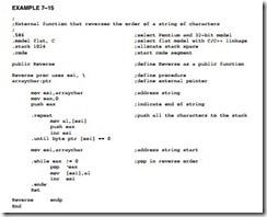
Example 7–15 illustrates a flat model procedure that will be linked to a C++ program. We denote that the assembly module is a C++ module by using the letter C after the word flat in the model statement. The linkage specified by the letter C is the same for the C or C++ languages. The flat model allows assembly language software to be any length up to 2G bytes. Note that the .586 switch appears before the model statement, which causes the assembler to generate code that functions in the protected 32-bit mode. The Reverse procedure, shown in Example 7–15, accepts a character string from a C++ program, reverses its order, and returns to the C++ program. Notice how this program uses conditional program flow instructions, which are not available with the inline assembler described in prior sections of this chapter. The assembly language module can have any name and it can contain more than one procedure, as long as each procedure contains a PUBLIC statement defining the name of the procedure as public. Any parameters that are transferred in the C++ program and the assembly language program are indicated with the backslash following the name of the procedure. This names the parameter for the assembly language program (it can be a different name in C++) and indicates the size of the parameter. The only thing that is not different in the C++ calling program and the assembly program is the order of the parameters. In this example, the parameter is a pointer to a character string and the result is returned as a replacement for the original string.

Using Assembly Language with C-C  -0263

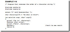
Example 7–16 illustrates a C++ language program for DOS console applications that uses the Reverse assembly language procedure. The EXTERN statement is used to indicate that an external procedure called Reverse is to be used in the C++ program. The name of the procedure is case-sensitive, so make sure that it is spelled the same in both the assembly language module and the C++ language module. The EXTERN statement in Example 7–16 shows that the external assembly language procedure transfers a character string to the procedure and returns no data. If data are returned from the assembly language procedure, data are returned as a value in register EAX for bytes, words, or doublewords. If floating-point numbers are returned, they must be returned on the floating-point coprocessor stack. If a pointer is returned, it must be in EAX.

Using Assembly Language with C-C  -0264

Once both the C++ program and the assembly language program are written, the Visual C++ development system must be set up to link the two together. For linking and assembly, we will assume that the assembly language module is called Reverse.txt (you cannot add an .asm extension file to the file list for inclusion into a project, so just use the .txt extension and add a .txt file) and the C++ language module is called Main.cpp. Both modules are stored in the C:PROJECTMINE directory or some other directory of your choosing. After the modules are placed in the same project workspace, the Programmer’s Workbench program is used to edit both assembly language and C++ language modules.

To set up the Visual C++ developer studio to compile, assemble, and link these files, follow these steps:

1. Start the developer studio and select New from the File menu.

a. Choose New Project.

b. When the Application Wizard appears, click on Visual C++ Projects.

c. Select C++ Console Application, and name the project Mine.

d. Then click on OK.

2. You will see the project in the Solution window at the left margin in the center. It will have a single file called Main.cpp, which is the C++ program file. Modify this to appear as in Example 7–16.

3. To add the assembly language module, right-click on the line Source Files and select Add from the menu. Choose Add New Item from the list. Scroll down the list of file types until you find Text Files and select it, then enter the file name as Reverse and click on Open. This creates the assembly module called Reverse.txt. You may enter the assembly code from Example 7–15 in this file.

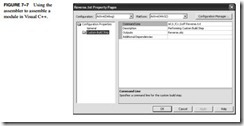
4. Under the Source Files listing in the Solution Explorer, right-click on Reverse.txt and select Properties. Figure 7–7 shows what to enter in this wizard after you click on the Custom Build step. Make sure you enter the object file name (Reverse.obj) in the Outputs box and ml /c /Cx /coff Reverse.txt in the Command Line box. The Reverse assembly language file will assemble and be included in the project.

5. Assuming both Examples 7–15 and 7–16 have been entered and you have completed all steps, the program will function.

Using Assembly Language with C-C  -0265Using Assembly Language with C-C  -0266

At last, you can execute the program. Click on the green arrow. You should see two lines of ASCII text data displayed. The first line is in correct forward order and the second is in reverse order. Although this is a trivial application, it does illustrate how to create and link C++ language with assembly language.

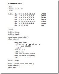
Now that we have a good understanding of interfacing assembly language with C++, we need a longer example that uses a few assembly language procedures with a C++ language pro- gram. Example 7–17 illustrates an assembly language package that includes a procedure (Scan) to test a character input against a lookup table and return a number that indicates the relative position in the table. A second procedure (Look) uses a number transferred to it and returns with a character string that represents Morse code. (The code is not important, but if you are interested, Table 7–2 lists Morse code.)

Using Assembly Language with C-C  -0267Using Assembly Language with C-C  -0268

The lookup table in Example 7–17 contains 2 bytes for each character between A and Z. For example, the code for A is a 2 for a Morse-coded character two of any combination of dashes or dots, and the 1 is the code for the letter a (. – ), where the binary equivalent 01 (for two digits) is a dot followed by a dash. This lookup table is accessed by the Scan procedure to obtain the correct Morse code from the lookup table, which is returned in AX as a parameter to the C++ language call. The remaining assembly code is mundane.

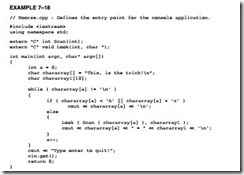
Example 7–18 lists the C++ program, which calls the two procedures listed in Example 7–17. This software is simple to understand, so we do not explain it.

Using Assembly Language with C-C  -0269

Although the examples presented here are for console applications, the same method of instructing Visual Studio to assemble and link an assembly language module is also used for Visual applications for Windows. The main difference is that Windows applications do not use printf or cout. The next chapter explains how library files can also be used with Visual C++ and also gives many more programming examples.

Adding New Assembly Language Instructions to C/C++ Programs

From time to time, as new microprocessors are introduced by Intel, new assembly language instructions are also introduced. These new instructions cannot be used in C++ unless you develop a macro for C++ to include them in the program. An example is the CPUID assembly language instruction. This will function in an _asm block within C++ because the inline assembler does not recognize it. Another group of newer instructions includes the MMX and SEC instructions. These are also recognized, but in order to illustrate how a new instruction is added that is not in the assembler, we show the technique. To use any new instructions, first look up the machine language code from Appendix B or from Intel’s website at www.intel.com. For example, the machine code for the CPUlD instruction is 0F A2. This 2-byte instruction can be defined as a C++ macro, as illustrated in Example 7–19. To use the new macro in a C++ program, all we need to type is CPUID. The _emit macro stores the byte that follows it in the program.

Using Assembly Language with C-C  -0270


USING ASSEMBLY LANGUAGE WITH C/C++:USING ASSEMBLY LANGUAGE WITH VISUAL C/C++ FOR 32-BIT APPLICATIONS.

USING ASSEMBLY LANGUAGE WITH VISUAL C/C++ FOR 32-BIT APPLICATIONS

A major difference exists between l6-bit and 32-bit applications. The 32-bit applications are written using Microsoft Visual C/C++ Express for Windows and the l6-bit applications are written using Microsoft C++ for DOS. The main difference is that Visual C/C++ Express for Windows is more common today, but Visual C/C++ Express cannot easily call DOS functions such as INT 2lH. It is suggested that embedded applications that do not require a visual interface be written in l6-bit C or C++, and applications that incorporate Microsoft Windows or Windows CE (available for use on a ROM or Flash1 device for embedded applications) use 32-bit Visual C/C++ Express for Windows.

A 32-bit application is written by using any of the 32-bit registers, and the memory space is essentially limited to 2G bytes for Windows. The free version of Visual C++ Express does not support 64-bit applications written in assembly language at this time. The only difference is that you may not use the DOS function calls; instead use the console getch() or getche() and putch C/C++ language functions available for use with DOS console applications. Embedded applications use direct assembly language instructions to access I/O devices in an embedded system. In the Visual interface, all I/O is handled by the Windows operating system framework.

Console applications in WIN32 run in native mode, which allow assembly language to be included in the program without anything other than the _asm keyword. Windows forms appli- cations are more challenging because they operate in the managed mode, which does not run in the native mode of the microprocessor. Managed applications operate in a pseudo mode that does not generate native code.

An Example that Uses Console I/O to Access the Keyboard and Display

Example 7–7 illustrates a simple console application that uses the console I/O commands to read and write data from the console. To enter this application (assuming Visual Studio .NET 2003 or Visual C++ Express is available), select a WIN32 console application in the new project option (see Figure 7–1). Notice that instead of using the customary stdio.h library, we use the conio.h library in this application. This example program displays any number between 0 and 1000 in all number bases between base 2 and base 16. Notice that the main program is not called main as it was in ear- lier versions of C/C++, but is called _tmain in the current version of Visual C/C++ Express when used with a console application. The argc is the argument count passed to the _tmain procedure from the command line, and the argv[] is an array that contains the command line argument strings.

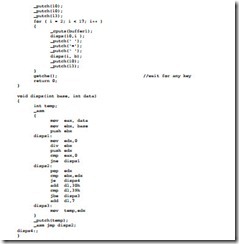
Using Assembly Language with C-C  -0250

Using Assembly Language with C-C  -0251

This example presents a mixture of assembly language and C/C++ language commands. The procedure disps (base,data) does most of the work for this program. It allows any integer (unsigned) to be displayed in any number base, which can be any value between base 2 and base 36. The upper limit occurs because letters of the alphabet only extend to the letter Z. If you need to convert larger number bases, a new scheme for bases over 36 must be developed. Perhaps the lowercase letters a through z can be used for base 37 to 52. Example 7–7 only displays the number that is entered in base 2 through base 16.

Directly Addressing I/O Ports

If a program is written that must access an actual port number, we can use console I/O commands such as the _inp(port) command to input byte data, and the _outp(port,byte_data) command to out- put byte data. When writing software for the personal computer, it is rare to directly address an I/O port, but when software is written for an embedded system, we often directly address an I/O port. An alternate to using the _inp and _outp commands is assembly language, which is more efficient in most cases. Be aware that I/O ports may not be accessed in the Windows environment if you are using Windows NT, Windows 2000, Windows XP, or Windows Vista. The only way to access the I/O ports in these modern operating systems is to develop a kernel driver. At this point in the text it would not be practical to develop such a driver. If you are using Windows 98 or even Windows 95, you can use inp and outp instructions in C/C++ to access the I/O ports directly.

Developing a Visual C++ Application for Windows

This section of the text shows how to use Visual C++ Express to develop a dialog-based application for the Microsoft Foundation Classes library. The Microsoft Foundation Classes (MFC) is a collection of classes that allows us to use the Windows interface without a great deal of difficulty. The MFC has been renamed to the common language runtime (CLR) in Visual C++ Express. The easiest application to learn and develop is a program that uses a forms application as presented here. This basic application type is used to program and test all of the software examples in this textbook written in the Visual C++ Express programming environment.

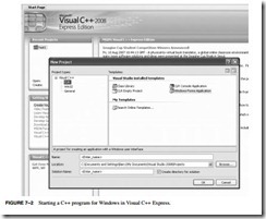
To create a Visual C++ form-based application, start Visual C++ Express and click on Create Project near the upper left corner of the start screen. (If you do not have the Visual C++ Express program, it is available for free from Microsoft at http://msdn.com.) Download and install the latest version, even of it is a beta version. Figure 7–2 illustrates what is displayed
Using Assembly Language with C-C  -0252Using Assembly Language with C-C  -0253

when the CLR Windows Forms application type is selected under Visual C++ Express Projects. Enter a name for the project and select an appropriate path for the project, then click on OK.

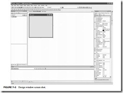
After a few moments the design screen should appear as in Figure 7–3. In the middle section is the form created by this application. To test the application, as it appears, just find the green arrow located somewhere above the form and below the Windows menu bar at the top of the screen and click on it to compile, link, and execute the dialog application. (Answer yes to “Would you like to build the application?”). Click on the X in the title bar to close the application. You have just created and tested your very first Visual C++ Express application.

When looking at the screen shot in Figure 7–3, several items are located in the image that are important to program creation and development. The right margin of the screen contains a Properties window, which contains the properties of the form. The left margin contains Solution Explorer. The tabs, located at the bottom of the Solution Explorer win- dow, allow other views to be displayed such as a class view and so forth in this area. The tabs at the bottom of the Properties window allow the classes, properties, dynamic help, or output to be displayed in this window. Your screen may or may not appear as the one illustrated in Figure 7–3 because it can be modified and probably will be modified as you use the program.

To create a simple application, select the toolbox by clicking on Tools at the top of the screen or by opening the View dropdown menu and selecting Toolbox from the list. Windows is

Using Assembly Language with C-C  -0254

an events-driven system so an object or a control is needed on the form to initiate an event. The control could be a button or almost any control object selected from the toolbox. Click on the button control near the top of the toolbox, which selects the button. Now move the mouse pointer (do not drag the button) over to the dialog application in the middle of the screen and draw, by left-clicking and resizing the button near the center (see Figure 7–4).

Once the button is placed on the screen, an event handler must be added to the application so that the act of pressing or clicking on the button can be handled. The event handlers are selected by going to the Properties window and clicking on the yellow lightning bolt

. Make sure that the item selected for events is the button1 object. To switch back to the Properties window from the event window, click on the icon just to the left of the lightning bolt. Locate the Click event (should be the first event) and then double-click on the textbox to the right to install the event handler for Click. The view will now switch to the code view and change the location of the button click software.

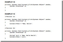
The software currently in view is the button1_Click function, which is called when the user clicks on the button. This procedure is illustrated in Example 7–8. To test the button, change the software in Example 7–8 to the software in Example 7–9(a). Click on the green arrow to compile, link, and execute the dialog application and click on button1 when it is running. The label on button1 will change to “Wow, Hello” if the button has been made wide enough. This is the first working application, but it does not use any assembly code. Example 7–9(a) uses the Text member property of the button1 object to change the text displayed on button1. A variant that uses a character string object (String^) appears in Example 7–9(b) to display “Wow, Hello World.”
Using Assembly Language with C-C  -0255

Now that a simple application has been written, we can modify it to illustrate a more complicated application as shown in Figure 7–5. The caption on the button has been changed to the word “Convert.” To return to the design screen, select the tab at the top of the program window that is labeled Form1.h[design]*. When in the Design window, change the caption on the button1 object by clicking the button and then finding the Text property from the properties of button1 in the Properties window. Change the Text property to “Convert.” In Figure 7–5 notice that there are three Label controls and three textbox controls in the illustration below and to the left of the Convert but- ton. These controls are located in the toolbox. Draw them on the screen in approximately the same
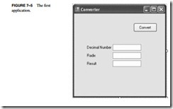
Using Assembly Language with C-C  -0256

place as in Figure 7–5. The labels are changed in properties for each label control. Change the text for each label as indicated.

Our goal in this example is to display any decimal number entered in the Decimal Number box as a number with any radix (number base) as selected by the number entered in the Radix box. The result appears in the Result box when the Convert button is clicked. To switch the view to the program view, click on the Form1.h tab at the top of the Design window.

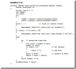
To obtain the value from an edit control, use Text property to obtain a string version of the number. The problem is that in this case an integer is needed and not a string. The string must be converted to an integer. The Convert class provided in C++ performs conversion from most data types to most data types. In this case, the Convert class member function ToInt32 is used to trans- form the string into an integer. The difficult portion of this example is the conversion from base 10 to any number base. Example 7–10 shows how the Convert class is used to convert the string from the textbox into an integer. This will only function correctly if the number entered into textbox1 is an integer. If a letter or anything else is entered, the program will crash and display an error.

Using Assembly Language with C-C  -0257

The remainder of the application appears in the button1_Click function of Example 7–12. This program uses the Horner’s algorithm to convert to any radix from 2 through 36. This con- version algorithm divides the number to be converted by the desired radix until the result is zero. After each division, the remainder is saved as a significant digit in the result and the quotient is divided again by the radix. Note that Windows does not use ASCII code, it uses Unicode so the Char (16-bit Unicode) is needed in place of the 8-bit char. Notice how the order of the remainders is placed into the result string by concatenating each digit to the left of the string. A 0x30 is added to each digit to convert to ASCII code in the example.

Horner’s algorithm:

1. Divide the number by the desired radix.

2. Save the remainder and replace the number with the quotient.

3. Repeat steps 1 and 2 until the quotient is zero.
Using Assembly Language with C-C  -0258

Since this is an assembly language text, the Convert class is not going to be used for good reason; the function is quite large. To see just how large, you can put a breakpoint in the software to the left of a Convert function by clicking on the gray bar to the left of the line of code. A brown circle, a breakpoint, will appear. If you run the program, it will break (stop) at this point and enter the debugging mode so it can be viewed in assembly language form. To display the disassembled code, run the program until it breaks, and then go to the Debug menu and select Windows. In the Windows menu, near the bottom, find “Disassembly.” The registers can also be displayed to step through a program in assembly language.

As you can see, if the program is debugged as described, this is a substantial amount of code that can be significantly reduced if it is rewritten using the inline assembler. Example 7–13 depicts the assembly language version of Convert::ToInt32 function. This function is considerably shorter (if debugged and viewed in the Disassemble window) and executes many times faster than the Convert in Example 7–12. This example points out the ineffi- ciency of the code generated by a high-level language, which may not always be important, but many cases require tight and efficient code, and that can only be written in assembly language. My guess is that as a plateau is reached on processor speed, more things will be written in assembly language. In addition, the new instructions such as MMX and SSE are not available in high-level languages. They require a very good working knowledge of assembly code.

The main problem with using inline assembly code is that the code cannot be placed into a Windows-managed forms application in a managed class. In order to use the assembler, the
Using Assembly Language with C-C  -0259

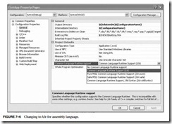
function must be placed before the managed class in order for it to compile. Therefore, in the project properties, Common Runtime Support must also be changed to /clr from the default set- ting of /clr:pure so it will compile successfully. (Refer to Figure 7–6 for a screen shot of how to change Common Language Runtime support to /clr.) A managed program runs under the virtual machine called .net and an unmanaged application operated in the native mode of the computer. The inline assembler generates native code for the microprocessor so it must be unmanaged and reside before the managed class in a program.

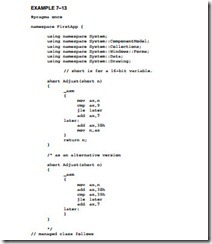
Example 7–13 illustrates how to replace part of the Horner’s algorithm with assembly code in a function called Adjust. The adjust function tests the number for 9, and if it’s greater than 9, it adds 0x07 and then 0x30 to convert it to ASCII, which is returned. Notice in the example that the assembly code is placed immediately following the using statements at the top of the program. This is where any assembly functions must be placed so a program can function correctly. The application starts in native mode and switches to managed mode when it encounters the managed class. By placing the assembly code before the managed class, it is available to the entire application and it executes in unmanaged or native mode.

At the end of Example 7–13 an alternative version of Adjust appears that is more efficient. The alternative version does not have a return instruction, so how can it function? What does not appear is that any assembly language function returns the value in AL for a byte, AX for a word or short, and EAX for an int. Note that the return value dictates the size of the value returned.
Using Assembly Language with C-C  -0260

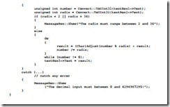
Figure 7–14 shows the modification to the button1_click function so that Adjust is called in place of the code that appears in Example 7–12. The code used to set up the form application that appears between Examples 7–13 and 7–14 is not shown. Notice that the assembly function uses short in place of character. A short is a 16-bit number used in unmanaged mode and a Char is a 16-bit number used in managed mode to represent a Unicode character. Here a cast is used to convert to a Char because without it, the numeric values are displayed instead of ASCII code.

Using Assembly Language with C-C  -0261Using Assembly Language with C-C  -0262


USING ASSEMBLY LANGUAGE WITH C/C++:USING ASSEMBLY LANGUAGE WITH C++ FOR 16-BIT DOS APPLICATIONS.

USING ASSEMBLY LANGUAGE WITH C/C++

INTRODUCTION

Today, it is rare to develop a complete system using only assembly language. We often use C/C++ with some assembly language to develop a system. The assembly language portion usually solves tasks (difficult or inefficient to accomplish in C/C++) that often include control soft- ware for peripheral interfaces and driver programs that use interrupts. Another application of assembly language in C/C++ programs is the MMX and SEC instructions that are part of the Pentium class microprocessor and not supported in C/C++. Although C++ does have macros for these commands, they are more complicated to use than using assembly language. This chapter develops the idea of mixing C/C++ and assembly language. Many applications in later chapters also illustrate the use of both assembly language and C/C++ to accomplish tasks for the microprocessor.

This text uses Microsoft Visual C/C++ Express, but programs can often be adapted to any version of C/C++, as long as it is standard ANSI (American National Standards Institute) format C/C++. If you want, you can use C/C++ to enter and execute all the programming applications in this text. The 16-bit applications are written by using Microsoft Visual C/C++ version 1.52 or newer (available [CL.EXE] for no cost as a legacy application in the Microsoft Windows Driver Development Kit [DDK]); the 32-bit applications are written using Microsoft Visual C/C++ version 6 or newer and preferably Microsoft Visual C/C++ version .NET 2003 or Visual C++ Express. The examples in the text are written assuming that you have the latest version of Visual C++ Express, which is a free downloadable version of Visual C++. Please visit http://msdn.com to obtain the Visual C++ Express program.

CHAPTER OBJECTIVES

Upon completion of this chapter, you will be able to:

1. Use assembly language in _asm blocks within C/C+.

2. Learn the rules that apply to mixed language software development.

3. Use common C/C++ data and structures with assembly language.

4. Use both the 16-bit (DOS) interface and the 32-bit (Microsoft Windows) interface with assembly language code.
5. Use assembly language objects with C/C++ programs.

USING ASSEMBLY LANGUAGE WITH C++ FOR 16-BIT DOS APPLICATIONS

This section shows how to incorporate assembly language commands within a C/C++ program. This is important because the performance of a program often depends on the incorporation of assembly language sequences to speed its execution. As mentioned in the introduction to the chapter, assembly language is also used for I/O operations in embedded systems. This text assumes that you are using a version of the Microsoft C/C++ program, but any C/C++ program should function as shown, if it supports inline assembly commands. The only change might be setting up the C/C++ package to function with assembly language. This section of the text assumes that you are building l6-bit applications for DOS. Make sure that your software can build l6-bit applications before attempting any of the programs in this section. If you build a 32-bit application and attempt to use the DOS INT 21H function, the program will crash because DOS calls are not directly allowed. In fact, they are inefficient to use in a 32-bit application.

To build a 16-bit DOS application, you will need the legacy 16-bit compiler usually found in the C:WINDDK2600.1106binwin_mebin16 directory of the Windows DDK. (The Windows driver development kit can be obtained for a small shipping charge from Microsoft Corporation.) The compiler is CL.EXE and the 16-bit linker program is LINK.EXE, both located in the directory or folder listed. Because the path in the computer that you are using probably points to the 32-bit linker program, it would be wise to work from this directory so the proper linker is used when linking the object files generated by the compiler. Compilation and linking must be performed at the command line because there is no visual interface or editor provided with the compiler and linker. Programs are generated using either Notepad or DOS Edit.

Basic Rules and Simple Programs

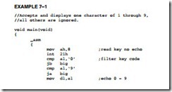
Before assembly language code can be placed in a C/C++ program, some rules must be learned. Example 7–1 shows how to place assembly code inside an assembly language block within a short C/C++ program. Note that all the assembly code in this example is placed in the _asm block. Labels are used as illustrated by the label big: in this example. It is also extremely important to use lowercase characters for any inline assembly code. If you use uppercase, you will find that some of the assembly language commands and registers are reserved or defined words in C/C++ language.

Example 7–1 uses no C/C++ commands except for the main procedure. Enter the program using either WordPad or Edit. This program (Example 7–1) reads one character from the console keyboard, and then filters it through assembly language so that only the numbers 0 through 9 are sent back to the video display. Although this programming example does not accomplish much, it does show how to set up and use some simple programming constructs in the C/C++ environment and also how to use the inline assembler.

Using Assembly Language with C-C  -0238Using Assembly Language with C-C  -0239

The register AX was not saved in Example 7–1, but it was used by the program. It is very important to note that the AX, BX, CX, DX, and ES registers are never used by Microsoft C/C++. (The function of AX on a return from a procedure is explained later in this chapter.) These registers, which might be considered scratchpad registers, are available to use with assembly language. If you wish to use any of the other registers, make sure that you save them with a PUSH before they are used and restore them with a POP afterwards. If you fail to save the registers used by a program, the program may not function correctly and can crash the computer. If the 80386 or above microprocessor is used as a base for the program, the EAX, EBX, ECX, EDX, and ES registers do not need to be saved. If any other registers are used, they must be saved or the program will crash.

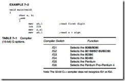
To compile the program, start the Command Prompt program located in the Start Menu under Accessories. Change the path to C:WINDDK2600.1106binwin_mebin16 if that is where you have your Windows DDK. You will also need to go to the C:WINDDK2600.1106 libwin_me directory and copy slibce.lib to the C:WINDDK2600.1106binwin_mebin16 directory. Make sure you saved the program in the same path and use the extension .c with the file name. If using Notepad, make sure you select All Files under File Type when saving. To compile the program, type CL /G3 filename.c>. This will generate the .exe file (/G3 is the 80386) for the program. (See Table 7–1 for a list of the /G compiler switches.) Any errors that appear are ignored by pressing the Enter key. These errors generate warnings that will not cause a problem when the program is executed. When the program is executed, you will only see a number echoed back to the DOS screen.

Example 7–2 shows how to use variables from C with a short assembly language program. In this example, the char variable type (a byte in C) is used to save space for a few 8-bit bytes of data. The program itself performs the operation X + Y = Z, where X and Y are two one-digit numbers, and Z is the result. As you might imagine, you could use the inline assembly in C to learn assembly language and write many of the programs in this textbook. The semicolon adds comments to the listing in the _asm block, just as with the normal assembler.

Using Assembly Language with C-C  -0240Using Assembly Language with C-C  -0241

What Cannot Be Used from MASM Inside an _asm Block

Although MASM contains some nice features, such as conditional commands (.IF, .WHILE,.REPEAT, etc.), the inline assembler does not include the conditional commands from MASM, nor does it include the MACRO feature found in the assembler. Data allocation with the inline assembler is handled by C instead of by using DB, DW, DD, etc. Just about all other features are supported by the inline assembler. These omissions from the inline assembler can cause some slight problems, as will be discussed in later sections of this chapter.

Using Character Strings

Example 7–3 illustrates a simple program that uses a character string defined with C and displays it so that each word is listed on a separate line. Notice the blend of both C statements and assem- bly language statements. The WHILE statement repeats the assembly language commands until the null (00H) is discovered at the end of the character string. If the null is not discovered, the assembly language instructions display a character from the string unless a space is located. For each space, the program displays a carriage return/line feed combination. This causes each word in the string to be displayed on a separate line.

Using Assembly Language with C-C  -0242Using Assembly Language with C-C  -0243

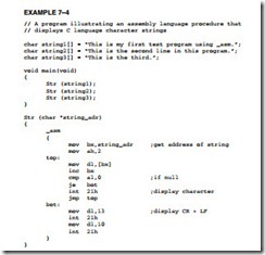
Suppose that you want to display more than one string in a program, but you still want to use assembly language to develop the software to display a string. Example 7–4 illustrates a program that creates a procedure displaying a character string. This procedure is called each time that a string is displayed in the program. Note that this program displays one string on each line, unlike Example 7–3.

Using Assembly Language with C-C  -0244

Using Data Structures

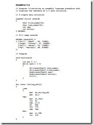
Data structures are an important part of most programs. This section shows how to interface a data structure created in C with an assembly language section that manipulates the data in the structure. Example 7–5 illustrates a short program that uses a data structure to store names, ages, and

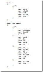
salaries. The program then displays each of the entries by using a few assembly language procedures. Although the string procedure displays a character string, shown in Example 7–4, no car- riage return/line feed combination is displayed—instead, a space is displayed. The Crlf procedure displays a carriage return/line feed combination. The Numb procedure displays the integer.

Using Assembly Language with C-C  -0245Using Assembly Language with C-C  -0246

An Example of a Mixed-Language Program

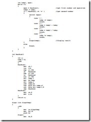
To see how this technique can be applied to any program, Example 7–6 shows how the program can do some operations in assembly language and some in C language. Here, the only assembly language portions of the program are the Dispn procedure that displays an integer and the Readnum procedure, which reads an integer. The program in Example 7–6 makes no attempt to detect or correct errors. Also, the program functions correctly only if the result is positive and less than 64K. Notice that this example uses assembly language to perform the I/O; the C portion performs all other operations to form the shell of the program.

Using Assembly Language with C-C  -0247Using Assembly Language with C-C  -0248Using Assembly Language with C-C  -0249


SUMMARY OF PROGRAM CONTROL INSTRUCTIONS.

SUMMARY

1. There are three types of unconditional jump instructions: short, near, and far. The short jump allows a branch to within +127 and -128 bytes. The near jump (using a displacement of ±32K) allows a jump to any location in the current code segment (intrasegment). The far jump allows a jump to any location in the memory system (intersegment). The near jump in an 80386 through a Core2 is within ±2G bytes because these microprocessors can use a 32-bit signed displacement.

2. Whenever a label appears with a JMP instruction or conditional jump, the label, located in the label field, must be followed by a colon (LABEL:). For example, the JMP DOGGY instruction jumps to memory location DOGGY:.

3. The displacement that follows a short or near jump is the distance from the next instruction to the jump location.

4. Indirect jumps are available in two forms: (1) jump to the location stored in a register and

(1) jump to the location stored in a memory word (near indirect) or doubleword (far indirect).

5. Conditional jumps are all short jumps that test one or more of the flag bits: C, Z, O, P, or S. If the condition is true, a jump occurs; if the condition is false, the next sequential instruction executes. Note that the 80386 and above allow a 16-bit signed displacement for the conditional jump instructions. In 64-bit mode, the displacement is 32 bits allowing a range of ±2G.

6. A special conditional jump instruction (LOOP) decrements CX and jumps to the label when CX is not 0. Other forms of loop include LOOPE, LOOPNE, LOOPZ, and LOOPNZ. The LOOPE instruction jumps if CX is not 0 and if an equal condition exists. In the 80386 through the Core2, the LOOPD, LOOPED, and LOOPNED instructions also use the ECX register as a counter. In the 64-bit mode, these instructions use the RCX register as for iteration.

7. The 80386 through the Core2 contain conditional set instructions that either set a byte to 01H or clear it to 00H. If the condition under test is true, the operand byte is set to 01H; if the condition under test is false, the operand byte is cleared to 00H.

8. The .IF and .ENDIF statements are useful in assembly language for making decisions. The instructions cause the assembler to generate conditional jump statements that modify the flow of the program.

9. The .WHILE and .ENDW statements allow an assembly language program to use the WHILE construction, and the .REPEAT and .UNTIL statements allow an assembly language program to use the REPEAT-UNTIL construct.

10. Procedures are groups of instructions that perform one task and are used from any point in a program. The CALL instruction links to a procedure and the RET instruction returns from a procedure. In assembly language, the PROC directive defines the name and type of procedure. The ENDP directive declares the end of the procedure.

11. The CALL instruction is a combination of a PUSH and a JMP instruction. When CALL exe- cutes, it pushes the return address on the stack and then jumps to the procedure. A near CALL places the contents of IP on the stack, and a far CALL places both IP and CS on the stack.

12. The RET instruction returns from a procedure by removing the return address from the stack and placing it into IP (near return), or IP and CS (far return).

13. Interrupts are either software instructions similar to CALL or hardware signals used to call procedures. This process interrupts the current program and calls a procedure. After the procedure, a special IRET instruction returns control to the interrupted software.

14. Real mode interrupt vectors are 4 bytes long and contain the address (IP and CS) of the interrupt service procedure. The microprocessor contains 256 interrupt vectors in the first 1K bytes of memory. The first 32 are defined by Intel; the remaining 224 are user interrupts. In protected mode operation, the interrupt vector is 8 bytes long and the interrupt vector table may be relocated to any section of the memory system.

15. Whenever an interrupt is accepted by the microprocessor, the flags IP and CS are pushed onto the stack. Besides pushing the flags, the T and I flag bits are cleared to disable both the trace function and the INTR pin. The final event that occurs for the interrupt is that the interrupt vector is fetched from the vector table and a jump to the interrupt service procedure occurs.

16. Software interrupt instructions (INT) often replace system calls. Software interrupts save 3 bytes of memory each time they replace CALL instructions.

17. A special return instruction (IRET) must be used to return from an interrupt service procedure. The IRET instruction not only removes IP and CS from the stack, it also removes the flags from the stack.

18. Interrupt on an overflow (INTO) is a conditional interrupt that calls an interrupt service procedure if the overflow flag (O) = 1.

19. The interrupt enable flag (I) controls the INTR pin connection on the microprocessor. If the STI instruction executes, it sets I to enable the INTR pin. If the CLI instruction executes, it clears I to disable the INTR pin.

20. The carry flag bit (C) is clear, set, and complemented by the CLC, STC, and CMC instructions.

21. The WAIT instruction tests the condition of the BUSY or TEST pin on the microprocessor.

If BUSY or TEST = 1, WAIT does not wait; but if BUSY or TEST = 0, WAIT continues test- ing the BUSY or TEST pin until it becomes a logic 1. Note that the 8086/8088 contains the TEST pin, while the 80286–80386 contain the BUSY pin. The 80486 through the Core2 do not contain a BUSY or TEST pin.

22. The LOCK prefix causes the LOCK pin to become a logic 0 for the duration of the locked instruction. The ESC instruction passes instruction to the numeric coprocessor.

23. The BOUND instruction compares the contents of any 16-bit register against the contents of two words of memory: an upper and a lower boundary. If the value in the register compared with memory is not within the upper and lower boundary, a type 5 interrupt ensues.


PROGRAM CONTROL INSTRUCTIONS:MACHINE CONTROL AND MISCELLANEOUS INSTRUCTIONS.

MACHINE CONTROL AND MISCELLANEOUS INSTRUCTIONS

The last category of real mode instructions found in the microprocessor is the machine control and miscellaneous group. These instructions provide control of the carry bit, sample the BUSY/TEST pin, and perform various other functions. Because many of these instructions are used in hardware control, they need only be explained briefly at this point.

Controlling the Carry Flag Bit

The carry flag (C) propagates the carry or borrow in multiple-word/doubleword addition and sub- traction. It also can indicate errors in assembly language procedures. Three instructions control the contents of the carry flag: STC (set carry), CLC (clear carry), and CMC (complement carry).

Because the carry flag is seldom used except with multiple-word addition and subtraction, it is available for other uses. The most common task for the carry flag is to indicate an error upon return from a procedure. Suppose that a procedure reads data from a disk memory file. This operation can be successful, or an error such as file-not-found can occur. Upon return from this procedure, if C = 1, an error has occurred; if C = 0, no error occurred. Most of the DOS and BIOS procedures use the carry flag to indicate error conditions. This flag is not available in Visual C/C++ for use with C++.

WAIT

The WAIT instruction monitors the hardware BUSY pin on the 80286 and 80386, and the TEST pin on the 8086/8088. The name of this pin was changed beginning with the 80286 microprocessor from TEST to BUSY. If the WAIT instruction executes while the BUSY pin = 1, nothing hap- pens and the next instruction executes. If the BUSY pin = 0 when the WAIT instruction executes, the microprocessor waits for the BUSY pin to return to a logic 1. This pin inputs a busy condition when at a logic 0 level.

The BUSY / TEST pin of the microprocessor is usually connected to the BUSY pin of the 8087 through the 80387 numeric coprocessors. This connection allows the microprocessor to wait until the coprocessor finishes a task. Because the coprocessor is inside an 80486 through the Core2, the BUSY pin is not present in these microprocessors.

HLT

The halt instruction (HLT) stops the execution of software. There are three ways to exit a halt: by an interrupt, by a hardware reset, or during a DMA operation. This instruction normally appears in a program to wait for an interrupt. It often synchronizes external hardware interrupts with the software system. Note that DOS and Windows both use interrupts extensively, so HLT will not halt the computer when operated under these operating systems.

NOP

When the microprocessor encounters a no operation instruction (NOP), it takes a short time to execute. In early years, before software development tools were available, a NOP, which per- forms absolutely no operation, was often used to pad software with space for future machine lan- guage instructions. If you are developing machine language programs, which are extremely rare, it is recommended that you place 10 or so NOPS in your program at 50-byte intervals. This is done in case you need to add instructions at some future point. A NOP may also find application in time delays to waste time. Realize that a NOP used for timing is not very accurate because of the cache and pipelines in modem microprocessors.

LOCK Prefix

The LOCK prefix appends an instruction and causes the LOCK pin to become a logic 0. The LOCK pin often disables external bus masters or other system components. The LOCK prefix causes the LOCK pin to activate for only the duration of a locked instruction. If more than one sequential instruction is locked, the LOCK pin remains a logic 0 for the duration of the sequence of locked instructions. The LOCK:MOV AL,[SI] instruction is an example of a locked instruction.

ESC

The escape (ESC) instruction passes instructions to the floating-point coprocessor from the microprocessor. Whenever an ESC instruction executes, the microprocessor provides the memory address, if required, but otherwise performs a NOP. Six bits of the ESC instruction provide the opcode to the coprocessor and begin executing a coprocessor instruction.

The ESC opcode never appears in a program as ESC and in itself is considered obsolete as an opcode. In its place are a set of coprocessor instructions (FLD, FST, FMUL, etc.) that assemble as ESC instructions for the coprocessor. More detail is provided in Chapter 13, which details the 8087–Core2 numeric coprocessors.

BOUND

The BOUND instruction, first made available in the 80186 microprocessor, is a comparison instruction that may cause an interrupt (vector type number 5). This instruction compares the contents of any 16-bit or 32-bit register against the contents of two words or doublewords of memory: an upper and a lower boundary. If the value in the register compared with memory is not within the upper and lower boundary, a type 5 interrupt ensues. If it is within the boundary, the next instruction in the program executes.

For example, if the BOUND SI,DATA instruction executes, word-sized location DATA contains the lower boundary, and word-sized location DATA+2 bytes contains the upper boundary. If the number contained in SI is less than memory location DATA or greater than memory location DATA+2 bytes, a type 5 interrupt occurs. Note that when this interrupt occurs, the return address points to the BOUND instruction, not to the instruction following BOUND. This differs from a normal interrupt, where the return address points to the next instruction in the program.

ENTER and LEAVE

The ENTER and LEAVE instructions, first made available to the 80186 microprocessor, are used with stack frames, which are mechanisms used to pass parameters to a procedure through the stack memory. The stack frame also holds local memory variables for the procedure. Stack frames provide dynamic areas of memory for procedures in multiuser environments.

The ENTER instruction creates a stack frame by pushing BP onto the stack and then loading BP with the uppermost address of the stack frame. This allows stack frame variables to be accessed through the BP register. The ENTER instruction contains two operands: The first operand specifies the number of bytes to reserve for variables on the stack frame, and the second specifies the level of the procedure.

Suppose that an ENTER 8,0 instruction executes. This instruction reserves 8 bytes of memory for the stack frame and the zero specifies level 0. Figure 6–10 shows the stack frame set up by this instruction. Note that this instruction stores BP onto the top of the stack. It then sub- tracts 8 from the stack pointer, leaving 8 bytes of memory space for temporary data storage. The uppermost location of this 8-byte temporary storage area is addressed by BP. The LEAVE instruction reverses this process by reloading both SP and BP with their prior values. The ENTER and LEAVE instructions were used to call C++ functions in Windows 3.1, but since then, CALL has been used in modern versions of Windows for C++ functions.

FIGURE 6–10 The stack frame created by the ENTER 8,0 instruction. Notice that BP is stored beginning at the top of the stack frame. This is followed by an 8-byte area called a stack frame.

Program Control InstructionsA-0237


PROGRAM CONTROL INSTRUCTIONS:INTRODUCTION TO INTERRUPTS.

INTRODUCTION TO INTERRUPTS

An interrupt is either a hardware-generated CALL (externally derived from a hardware signal) or a software-generated CALL (internally derived from the execution of an instruction or by some other internal event). At times, an internal interrupt is called an exception. Either type interrupts the program by calling an interrupt service procedure (ISP) or interrupt handler.

This section explains software interrupts, which are special types of CALL instructions. This section describes the three types of software interrupt instructions (INT, INTO, and INT 3), provides a map of the interrupt vectors, and explains the purpose of the special interrupt return instruction (IRET).

Interrupt Vectors

An interrupt vector is a 4-byte number stored in the first 1024 bytes of the memory (00000H–003FFH) when the microprocessor operates in the real mode. In the protected mode, the vector table is replaced by an interrupt descriptor table that uses 8-byte descriptors to describe each of the interrupts. There are 256 different interrupt vectors, and each vector contains the address of an interrupt service procedure. Table 6–4 lists the interrupt vectors, with a brief description and the memory location of each vector for the real mode. Each vector contains a value for IP and CS that forms the address of the interrupt service procedure. The first 2 bytes contain the IP, and the last 2 bytes contain the CS.

Program Control InstructionsA-0234

Intel reserves the first 32 interrupt vectors for the present and future microprocessor products. The remaining interrupt vectors (32–255) are available for the user. Some of the reserved vectors are for errors that occur during the execution of software, such as the divide error interrupt. Some vectors are reserved for the coprocessor. Still others occur for normal events in the system. In a personal computer, the reserved vectors are used for system functions, as detailed later in this section. Vectors 1–6, 7, 9, 16, and 17 function in the real mode and protected mode; the remaining vectors function only in the protected mode.

Interrupt Instructions

The microprocessor has three different interrupt instructions that are available to the programmer: INT, INTO, and INT 3. In the real mode, each of these instructions fetches a vector from the vector table, and then calls the procedure stored at the location addressed by the vector. In the protected mode, each of these instructions fetches an interrupt descriptor from the interrupt descriptor table. The descriptor specifies the address of the interrupt service procedure. The interrupt call is similar to a far CALL instruction because it places the return address (IP/EIP and CS) on the stack.

INTs. There are 256 different software interrupt instructions (INTs) available to the programmer. Each INT instruction has a numeric operand whose range is 0 to 255 (00H–FFH). For example, the INT 100 uses interrupt vector 100, which appears at memory address 190H–193H. The address of the interrupt vector is determined by multiplying the interrupt type number by 4. For example, the INT 10H instruction calls the interrupt service procedure whose address is stored beginning at memory location 40H (10H × 4) in the real mode. In the protected mode, the interrupt descriptor is located by multiplying the type number by 8 instead of 4 because each descriptor is 8 bytes long.

Each INT instruction is 2 bytes long. The first byte contains the opcode, and the second byte contains the vector type number. The only exception to this is INT 3, a 1-byte special soft- ware interrupt used for breakpoints.

Whenever a software interrupt instruction executes, it (1) pushes the flags onto the stack, (2) clears the T and I flag bits, (3) pushes CS onto the stack, (4) fetches the new value for CS from the interrupt vector, (5) pushes IP/EIP onto the stack, (6) fetches the new value for IP/EIP from the vector, and (7) jumps to the new location addressed by CS and IP/EIP.

The INT instruction performs as a far CALL except that it not only pushes CS and IP onto the stack, but it also pushes the flags onto the stack. The INT instruction performs the operation of a PUSHF, followed by a far CALL instruction.

Notice that when the INT instruction executes, it clears the interrupt flag (I), which controls the external hardware interrupt input pin INTR (interrupt request). When I = 0, the micro- processor disables the INTR pin; when I = 1, the microprocessor enables the INTR pin.

Software interrupts are most commonly used to call system procedures because the address of the system function need not be known. The system procedures are common to all system and application software. The interrupts often control printers, video displays, and disk drives. Besides relieving the program from remembering the address of the system call, the INT instruction replaces a far CALL that would otherwise be used to call a system function. The INT instruction is 2 bytes long, whereas the far CALL is 5 bytes long. Each time that the INT instruction replaces a far CALL, it saves 3 bytes of memory in a program. This can amount to a sizable saving if the INT instruction often appears in a program, as it does for system calls.

IRET/IRETD. The interrupt return instruction (IRET) is used only with software or hardware interrupt service procedures. Unlike a simple return instruction (RET), the IRET instruction will (1) pop stack data back into the IP, (2) pop stack data back into CS, and (3) pop stack data back into the flag register. The IRET instruction accomplishes the same tasks as the POPF, followed by a far RET instruction.

Whenever an IRET instruction executes, it restores the contents of I and T from the stack. This is important because it preserves the state of these flag bits. If interrupts were enabled before an interrupt service procedure, they are automatically re-enabled by the IRET instruction because it restores the flag register.

In the 80386 through the Core2 processors, the IRETD instruction is used to return from an interrupt service procedure that is called in the protected mode. It differs from the IRET because it pops a 32-bit instruction pointer (EIP) from the stack. The IRET is used in the real mode and the IRETD is used in the protected mode.

INT 3. An INT 3 instruction is a special software interrupt designed to function as a breakpoint. The difference between it and the other software interrupts is that INT 3 is a 1-byte instruction, while the others are 2-byte instructions.

It is common to insert an INT 3 instruction in software to interrupt or break the flow of the software. This function is called a breakpoint. A breakpoint occurs for any software interrupt, but because INT 3 is 1 byte long, it is easier to use for this function. Breakpoints help to debug faulty software.

INTO. Interrupt on overflow (INTO) is a conditional software interrupt that tests the overflow flag (O). If O = 0, the INTO instruction performs no operation; if O = 1 and an INTO instruction executes, an interrupt occurs via vector type number 4.

The INTO instruction appears in software that adds or subtracts signed binary numbers. With these operations, it is possible to have an overflow. Either the JO instruction or INTO instruction detects the overflow condition.

An Interrupt Service Procedure. Suppose that, in a particular system, a procedure is required to add the contents of DI, SI, BP, and BX and then save the sum in AX. Because this is a common task in this system, it may occasionally be worthwhile to develop the task as a software interrupt. Realize that interrupts are usually reserved for system events and this is merely an example showing how an interrupt service procedure appears. Example 6–18 shows this software interrupt. The main difference between this procedure and a normal far procedure is that it ends with the IRET instruction instead of the RET instruction, and the contents of the flag register are saved on the stack during its execution. It is also important to save all registers that are changed by the procedure using USES.

Program Control InstructionsA-0235

Interrupt Control

Although this section does not explain hardware interrupts, two instructions are introduced that control the INTR pin. The set interrupt flag instruction (STI) places a 1 into the I flag bit, which enables the INTR pin. The clear interrupt flag instruction (CLI) places a 0 into the I flag bit, which disables the INTR pin. The STI instruction enables INTR and the CLI instruction disables INTR. In a software interrupt service procedure, hardware interrupts are enabled as one of the first steps. This is accomplished by the STI instruction. The reason interrupts are enabled early in an interrupt service procedure is that just about all of the I/O devices in the personal computer are interrupt-processed. If the interrupts are disabled too long, severe system problems result.

Program Control InstructionsA-0236

Interrupts in the Personal Computer

The interrupts found in the personal computer differ somewhat from the ones presented in Table 6–4. The reason that they differ is that the original personal computers are 8086/8088- based systems. This meant that they only contained Intel-specified interrupts 0–4. This design has been carried forward so that newer systems are compatible with the early personal computers.

Access to the protected mode interrupt structure in use by Windows is accomplished through kernel functions Microsoft provides and cannot be directly addressed. Protected mode interrupts use an interrupt descriptor table, which is beyond the scope of the text at this point. Protected mode interrupts are discussed completely in later chapters.

Figure 6–9 illustrates the interrupts available in the author’s computer. The interrupt assignments are viewable in the control panel of Windows under Performance and Maintenance by clicking on System and selecting Hardware and then Device Manager. Now click on View and select Device by Type and finally Interrupts.

64-Bit Mode Interrupts

The 64-bit system uses the IRETQ instruction to return from an interrupt service procedure. The main difference between IRET/IRETD and the IRETQ instruction is that IRETQ retrieves an 8-byte return address from the stack. The IRETQ instruction also retrieves the 32-bit EFLAG register from the stack and places it into the RFLAG register. It appears that Intel has no plans for using the leftmost 32 bits of the RFLAG register. Otherwise, 64-bit mode interrupts are the same as 32-bit mode interrupts.


PROGRAM CONTROL INSTRUCTIONS:PROCEDURES.

PROCEDURES

The procedure (subroutine, method, or function) is an important part of any computer system’s architecture. A procedure is a group of instructions that usually performs one task. A procedure is a reusable section of the software that is stored in memory once, but used as often as necessary. This saves memory space and makes it easier to develop software. The only disadvantage of a procedure is that it takes the computer a small amount of time to link to the procedure and return from it. The CALL instruction links to the procedure, and the RET (return) instruction returns from the procedure.

The stack stores the return address whenever a procedure is called during the execution of a program. The CALL instruction pushes the address of the instruction following the CALL (return address) on the stack. The RET instruction removes an address from the stack so the program returns to the instruction following the CALL.

With the assembler, there are specific rules for storing procedures. A procedure begins with the PROC directive and ends with the ENDP directive. Each directive appears with the name of the procedure. This programming structure makes it easy to locate the procedure in a program listing. The PROC directive is followed by the type of procedure: NEAR or FAR. Example 6–16 shows how the assembler uses the definition of both a near (intrasegment) and far (intersegment) procedure. In MASM version 6.x, the NEAR or FAR type can be followed by the USES statement. The USES statement allows any number of registers to be automatically pushed to the stack and popped from the stack within the procedure. The USES statement is also illustrated in Example 6–14.

Program Control InstructionsA-0226

When these first two procedures are compared, the only difference is the opcode of the return instruction. The near return instruction uses opcode C3H and the far return uses opcode CBH. A near return removes a 16-bit number from the stack and places it into the instruction pointer to return from the procedure in the current code segment. A far return removes a 32-bit number from the stack and places it into both IP and CS to return from the procedure to any memory location.

Procedures that are to be used by all software (global) should be written as far procedures. Procedures that are used by a given task (local) are normally defined as near procedures. Most procedures are near procedures.

FIGURE 6–6 The effect of a near CALL on the stack and the instruction pointer.

Program Control InstructionsA-0227

CALL

The CALL instruction transfers the flow of the program to the procedure. The CALL instruction differs from the jump instruction because a CALL saves a return address on the stack. The return address returns control to the instruction that immediately follows the CALL in a program when a RET instruction executes.

Near CALL. The near CALL instruction is 3 bytes long; the first byte contains the opcode, and the second and third bytes contain the displacement, or distance of ±32K in the 8086 through the 80286 processors. This is identical to the form of the near jump instruction. The 80386 and above use a 32- bit displacement, when operating in the protected mode, that allows a distance of ±2G bytes. When the near CALL executes, it first pushes the offset address of the next instruction onto the stack. The offset address of the next instruction appears in the instruction pointer (IP or EIP). After saving this return address, it then adds the displacement from bytes 2 and 3 to the IP to transfer control to the procedure. There is no short CALL instruction. A variation on the opcode exists as CALLN, but this should be avoided in favor of using the PROC statement to define the CALL as near.

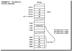
Why save the IP or EIP on the stack? The instruction pointer always points to the next instruction in the program. For the CALL instruction, the contents of IP/EIP are pushed onto the stack, so program control passes to the instruction following the CALL after a procedure ends. Figure 6–6 shows the return address (IP) stored on the stack and the call to the procedure.

Far CALL. The far CALL instruction is like a far jump because it can call a procedure stored in any memory location in the system. The far CALL is a 5-byte instruction that contains an opcode followed by the next value for the IP and CS registers. Bytes 2 and 3 contain the new contents of the IP, and bytes 4 and 5 contain the new contents for CS.

The far CALL instruction places the contents of both IP and CS on the stack before jumping to the address indicated by bytes 2 through 5 of the instruction. This allows the far CALL to call a procedure located anywhere in the memory and return from that procedure.

Program Control InstructionsA-0228

Figure 6–7 shows how the far CALL instruction calls a far procedure. Here, the contents of IP and CS are pushed onto the stack. Next, the program branches to the procedure. A variant of the far call exists as CALLF, but this should be avoided in favor of defining the type of call instruction with the PROC statement.

In the 64-bit mode a far call is to any memory location and the information placed onto the stack is an 8-byte number. Likewise, the far return instruction also retrieves an 8-byte return address from the stack and places it into RIP.

CALLs with Register Operands. Like jump instructions, call instructions also may contain a register operand. An example is the CALL BX instruction, which pushes the contents of IP onto the stack. It then jumps to the offset address, located in register BX, in the current code segment. This type of CALL always uses a 16-bit offset address, stored in any 16-bit register except the segment registers.

Example 6–15 illustrates the use of the CALL register instruction to call a procedure that begins at offset address DISP. (This call could also directly call the procedure by using the CALL DISP instruction.) The OFFSET address DISP is placed into the BX register, and then the CALL BX instruction calls the procedure beginning at address DISP. This program displays an “OK” on the monitor screen.

Program Control InstructionsA-0229Program Control InstructionsA-0230

CALLs with Indirect Memory Addresses. A CALL with an indirect memory address is particularly useful whenever different subroutines need to be chosen in a program. This selection process is often keyed with a number that addresses a CALL address in a lookup table. This is essentially the same as the indirect jump that used a lookup table for a jump address earlier in this chapter.

Example 6–16 shows how to access a table of addresses using an indirect CALL instruction. This table illustrated in the example contains three separate subroutine addresses referenced by the numbers 0, 1, and 2. This example uses the scaled-index addressing mode to multiply the number in EBX by 2 so it properly accesses the correct entry in the lookup table.

Program Control InstructionsA-0231

The CALL instruction also can reference far pointers if the instruction appears as CALL FAR PTR [4*EBX] or as CALL TABLE [4*EBX], if the data in the table are defined as double- word data with the DD directive. These instructions retrieve a 32-bit address (4 bytes long) from the data segment memory location addressed by EBX and use it as the address of a far procedure.

RET

The return instruction (RET) removes a 16-bit number (near return) from the stack and places it into IP, or removes a 32-bit number (far return) and places it into IP and CS. The near and far return instructions are both defined in the procedure’s PROC directive, which automatically selects the proper return instruction. With the 80386 through the Pentium 4 processors operating in the protected mode, the far return removes 6 bytes from the stack. The first 4 bytes contain the new value for EIP and the last 2 contain the new value for CS. In the 80386 and above, a protected mode near return removes 4 bytes from the stack and places them into EIP.

When IP/EIP or IP/EIP and CS are changed, the address of the next instruction is at a new memory location. This new location is the address of the instruction that immediately follows the most recent CALL to a procedure. Figure 6–8 shows how the CALL instruction links to a procedure and how the RET instruction returns in the 8086–Core2 operating in the real mode.

There is one other form of the return instruction, which adds a number to the contents of the stack pointer (SP) after the return address is removed from the stack. A return that uses an immediate operand is ideal for use in a system that uses the C/C++ or PASCAL calling conventions. (This is true even though the C/C++ and PASCAL calling conventions require the caller to remove stack data for many functions.) These conventions push parameters on the stack before near return instruction on the stack and instruction pointer.

Program Control InstructionsA-0232

calling a procedure. If the parameters are to be discarded upon return, the return instruction contains a number that represents the number of bytes pushed to the stack as parameters.

Example 6–17 shows how this type of return erases the data placed on the stack by a few pushes. The RET 4 adds a 4 to SP after removing the return address from the stack. Because the PUSH AX and PUSH BX together place 4 bytes of data on the stack, this return effectively deletes AX and BX from the stack. This type of return rarely appears in assembly language programs, but it is used in high-level programs to clear stack data after a procedure. Notice how parameters are addressed on the stack by using the BP register, which by default addresses the stack segment. Parameter stacking is common in procedures written for C++ or PASCAL by using the C++ or PASCAL calling conventions.

Program Control InstructionsA-0233

As with the CALLN and CALLF instructions, there are also variants of the return instruction: RETN and RETF. As with the CALLN and CALLF instructions, these variants should also be avoided in favor of using the PROC statement to define the type of call and return.


PROGRAM CONTROL INSTRUCTIONS:CONTROLLING THE FLOW OF THE PROGRAM.

CONTROLLING THE FLOW OF THE PROGRAM

It is much easier to use the assembly language statements .IF, .ELSE, .ELSEIF, and .ENDIF to control the flow of the program than it is to use the correct conditional jump statement. These statements always indicate a special assembly language command to MASM. Note that the control flow assembly language statements beginning with a period are only available to MASM version 6.xx, and not to earlier versions of the assembler such as 5.10. Other statements developed in this chapter include the .REPEAT–.UNTIL and .WHILE–.ENDW statements. These statements (the dot commands) do not function when using the Visual C++ inline assembler.

Example 6–8(a) shows how these statements are used to control the flow of a program by testing AL for the ASCII letters A through F. If the contents of AL are A through F, 7 is subtracted from AL.

Accomplishing the same task using the Visual C++ inline assembler is usually handled in C++ rather than in assembly language. Example 6–8(b) shows the same task using the inline assembler in Visual C++ and conditional jumps in assembly language. It also shows how to use a label in an assembly block in Visual C++. This illustrates that it is more difficult to accomplish the same task without the dot commands. Never use uppercase for assembly language commands with the inline assembler because some of them are reserved by C++ and will cause problems.

Program Control InstructionsA-0218

In Example 6–8(a) notice how the && symbol represents the AND function in the .IF statement. There is no .if in Example 6–8(b) because the same operation was performed by using a few compare (CMP) instructions to accomplish the same task. See Table 6–3 for a complete list of relational operators used with the .IF statement. Note that many of these conditions (such as &&) are also used by many high-level languages such as C/C++.

Example 6–9 shows another example of the conditional .IF directive that converts all ASCII-coded letters to uppercase. First, the keyboard is read without echo using DOS INT 21H function 06H, and then the .IF statement converts the character into uppercase, if needed. In this example, the logical AND function (&&) is used to determine if the character is in lowercase. If it is lowercase, 20H is subtracted, converting to uppercase. This program reads a key from the

Program Control InstructionsA-0219

keyboard and converts it to uppercase before displaying it. Notice also how the program terminates when the control C key (ASCII = 03H) is typed. The .LISTALL directive causes all assembler- generated statements to be listed, including the label @Startup generated by the .STARTUP directive. The .EXIT directive also is expanded by .LISTALL to show the use of the DOS INT 21H function 4CH, which returns control to DOS.

Program Control InstructionsA-0220

In this program, a lowercase letter is converted to uppercase by the use of the .IF AL >= ‘a’ && AL <= ‘z’ statement. If AL contains a value that is greater than or equal to a lowercase a, and less than or equal to a lowercase z (a value of a through z), the statement between the .IF and .ENDIF executes. This statement (SUB AL,20H) subtracts 20H from the lowercase letter to change it to an uppercase letter. Notice how the assembler program implements the .IF statement (see lines that begin with *). The label @C0001 is an assembler-generated label used by the conditional jump statements placed in the program by the .IF statement.

Another example that uses the conditional .IF statement appears in Example 6–10. This program reads a key from the keyboard, and then converts it to hexadecimal code. This program is not listed in expanded form.

In this example, the .IF AL >=‘a’ && AL<=‘f’ statement causes the next instruction (SUB AL,57H) to execute if AL contains letters a through f, converting them to hexadecimal. If it is not between letters a and f, the next .ELSEIF statement tests it for the letters A through F. If it is the letters A through F, 37H is subtracted from AL. If neither condition is true, 30H is subtracted from AL before AL is stored at data segment memory location TEMP. The same conversion can be performed in a C++ function as illustrated in the program snippet of Example 6–10(b).

Program Control InstructionsA-0221

WHILE Loops

As with most high-level languages, the assembler also provides the WHILE loop construct, available to MASM version 6.x. The .WHILE statement is used with a condition to begin the loop, and the .ENDW statement ends the loop.

Example 6–11 shows how the .WHILE statement is used to read data from the keyboard and store it into an array called BOP until the enter key (0DH) is typed. This program assumes that BUF is stored in the extra segment because the STOSB instruction is used to store the key- board data in memory. Note that the .WHILE loop portion of the program is shown in expanded form so that the statements inserted by the assembler (beginning with a *) can be studied. After the Enter key (0DH) is typed, the string is appended with a $ so it can be displayed with DOS INT 21H function number 9.

Program Control InstructionsA-0222Program Control InstructionsA-0223

The program in Example 6–11 functions perfectly, as long as we arrive at the .WHILE statement with AL containing some other value except 0DH. This can be corrected by adding a MOV AL,0DH instruction before the .WHILE statement in Example 6–11. Although not shown in an example, the .BREAK and .CONTINUE statements are available for use with the while loop. The .BREAK statement is often followed by the .IF statement to select the break condition as in .BREAK .IF AL == 0DH. The .CONTINUE statement, which can be used to allow the DO–.WHILE loop to continue if a certain condition is met, can be used with .BREAK. For example, .CONTINUE .IF AL == 15 allows the loop to continue if AL equals 15. Note that the .BREAK and .CONTINUE commands function in the same manner in a C++ program.

REPEAT-UNTIL Loops

Also available to the assembler is the REPEAT–UNTIL construct. A series of instructions is repeated until some condition occurs. The .REPEAT statement defines the start of the loop; the end is defined with the .UNTIL statement, which contains a condition. Note that .REPEAT and .UNTIL are available to version 6.x of MASM.

If Example 6–11 is again reworked by using the REPEAT-UNTIL construct, this appears to be the best solution. See Example 6–12 for the program that reads keys from the keyboard and stores keyboard data into extra segment array BUF until the enter key is pressed. This pro- gram also fills the buffer with keyboard data until the Enter key (0DH) is typed. Once the Enter key is typed, the program displays the character string using DOS INT 2lH function number 9, after appending the buffer data with the required dollar sign. Notice how the .UNTIL AL == 0DH statement generates code (statements beginning with *) to test for the Enter key.

Program Control InstructionsA-0224

There is also an .UNTILCXZ instruction available that uses the LOOP instruction to check CX for a repeat loop. The .UNTILCXZ instruction uses the CX register as a counter to repeat a loop a fixed number of times. Example 6–13 shows a sequence of instructions that uses the .UNTILCXZ instruction used to add the contents of byte-sized array ONE to byte- sized array TWO. The sums are stored in array THREE. Note that each array contains 100 bytes of data, so the loop is repeated 100 times. This example assumes that array THREE is in the extra segment, and that arrays ONE and TWO are in the data segment. Notice how the LOOP instruction is inserted for the .UNTILCXZ.

Program Control InstructionsA-0225