8086/8088 HARDWARE SPECIFICATIONS:BUS BUFFERING AND LATCHING.

BUS BUFFERING AND LATCHING

Before the 8086/8088 microprocessors can be used with memory or I/O interfaces, their multiplexed buses must be demultiplexed. This section provides the detail required to demultiplex the buses and illustrates how the buses are buffered for very large systems. (Because the maximum fan-out is 10, the system must be buffered if it contains more than 10 other components.)

Demultiplexing the Buses

The address/data bus on the 8086/8088 is multiplexed (shared) to reduce the number of pins required for the 8086/8088 microprocessor integrated circuit. Unfortunately, this burdens the hardware designer with the task of extracting or demultiplexing information from these multiplexed pins.

Why not leave the buses multiplexed? Memory and I/O require that the address remains valid and stable throughout a read or write cycle. If the buses are multiplexed, the address changes at the memory and I/O, which causes them to read or write data in the wrong locations.

All computer systems have three buses: (1) an address bus that provides the memory and I/O with the memory address or the I/O port number, (2) a data bus that transfers data between the micro- processor and the memory and I/O in the system, and (3) a control bus that provides control signals to the memory and I/O. These buses must be present in order to interface to memory and I/O.

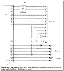
Demultiplexing the 8088. Figure 9–5 illustrates the 8088 microprocessor and the components required to demultiplex its buses. In this case, two 74LS373 or 74LS573 transparent latches are used to demultiplex the address/data bus connections AD7–AD0 and the multiplexed address/ status connections A19/S6–A16/S3.

These transparent latches, which are like wires whenever the address latch enable pin (ALE) becomes a logic 1, pass the inputs to the outputs. After a short time, ALE returns to its logic 0 condition, which causes the latches to remember the inputs at the time of the change to a

8086-8088 Hardware Specifications-0008

logic 0. In this case, A7–A0 are stored in the bottom latch and A19–A16 are stored in the top latch. This yields a separate address bus with connections A19–A0. These address connections allow the 8088 to address 1M byte of memory space. The fact that the data bus is separate allows it to be connected to any 8-bit peripheral device or memory component.

Demultiplexing the 8086. Like the 8088, the 8086 system requires separate address, data, and control buses. It differs primarily in the number of multiplexed pins. In the 8088, only AD7–AD0 and A19/S6–A16/S3 are multiplexed. In the 8086, the multiplexed pins include AD15–AD0 A19/S6–A16/S3, and BHE/S7. All of these signals must be demultiplexed.

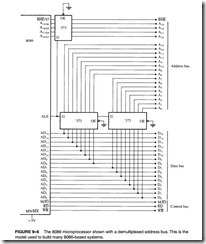
 Figure 9–6 illustrates a demultiplexed 8086 with all three buses: address (A19–A0 and BHE), data (D15–D0), and control (M>IO, RD, and WR).

This circuit shown in Figure 9–6 is almost identical to the one pictured in Figure 9–5, except that an additional 74LS373 latch has been added to demultiplex the address/data bus pins AD15–AD8 and a BHE/S7 input has been added to the top 74LS373 to select the high-order memory bank in the l6-bit memory system of the 8086. Here, the memory and I/O system see the

8086-8088 Hardware Specifications-0009

8086 as a device with a 20-bit address bus (A19–A0), a l6-bit data bus (D15–D0), and a three-line control bus (M>IO, RD, and WR).

The Buffered System

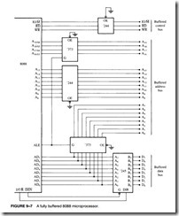
If more than 10 unit loads are attached to any bus pin, the entire 8086 or 8088 system must be buffered. The demultiplexed pins are already buffered by the 74LS373 or 74LS573 latches, which have been designed to drive the high-capacitance buses encountered in microcomputer systems. The buffer’s output currents have been increased so that more TTL unit loads may be driven: A logic 0 output provides up to 32 mA of sink current, and a logic 1 output provides up to 5.2 mA of source current.

A fully buffered signal will introduce a timing delay to the system. This causes no difficulty unless memory or I/O devices are used, which function at near the maximum speed of the bus. Section 9–4 discusses this problem and the time delays involved in more detail.

clip_image007[1]The Fully Buffered 8088. Figure 9–7 depicts a fully buffered 8088 microprocessor. Notice that the remaining eight address pins, A15–A8, use a 74LS244 octal buffer; the eight data bus pins, D7–D0, use a 74LS245 octal bidirectional bus buffer; and the control bus signals, M>IO, RD,

8086-8088 Hardware Specifications-0010

and WR, use a 74LS244 buffer. A fully buffered 8088 system requires two 74LS244s, one 74LS245, and two 74LS373s. The direction of the 74LS245 is controlled by the DT/R signal and is enabled and disabled by the DEN signal.

The Fully Buffered 8086. Figure 9–8 illustrates a fully buffered 8086 microprocessor. Its address pins are already buffered by the 74LS373 address latches; its data bus employs two

8086-8088 Hardware Specifications-0011

74LS245 octal bidirectional bus buffers; and the control bus signals, M>IO, RD, and WR use a 74LS244 buffer. A fully buffered 8086 system requires one 74LS244, two 74LS245s, and three 74LS373s. The 8086 requires one more buffer than the 8088 because of the extra eight data bus connections, D15–D8. It also has a BHE signal that is buffered for memory-bank selection.


8086/8088 HARDWARE SPECIFICATIONS:PIN-OUTS AND THE PIN FUNCTIONS.

8086/8088 HARDWARE SPECIFICATIONS

INTRODUCTION

In this chapter, the pin functions of both the 8086 and 8088 microprocessors are detailed and information is provided on the following hardware topics: clock generation, bus buffering, bus latching, timing, wait states, and minimum mode operation versus maximum mode operation. These simple microprocessors are explained first, because of their less intricate structures, as an introduction to the Intel microprocessor family.

Before it is possible to connect or interface anything to the microprocessor, it is necessary to understand the pin functions and timing. These rudimentary microprocessors contain the same basic pins as the latest Pentium 4 or Core2 microprocessor. Thus, the information in this chapter is essential to a complete understanding of memory and I/O interfacing, which we cover in the later chapters of the text.

CHAPTER OBJECTIVES

Upon completion of this chapter, you will be able to:

1. Describe the function of each 8086 and 8088 pin.

2. Understand the microprocessor’s DC characteristics and indicate its fan-out to common logic families.

3. Use the clock generator chip (8284A) to provide the clock for the microprocessor.

4. Connect buffers and latches to the buses.

5. Interpret the timing diagrams.

6. Describe wait states and connect the circuitry required to cause various numbers of waits.

7. Explain the difference between minimum and maximum mode operation.

PIN-OUTS AND THE PIN FUNCTIONS

In this section, we explain the function and (in certain instances) the multiple functions of each of the microprocessor’s pins. In addition, we discuss the DC characteristics to provide a basis for understanding the later sections on buffering and latching.

The Pin-Out

Figure 9–1 illustrates the pin-outs of the 8086 and 8088 microprocessors. As a close comparison reveals, there is virtually no difference between these two microprocessors—both are packaged in 40-pin dual in-line packages (DIPs).

As mentioned in Chapter 1, the 8086 is a 16-bit microprocessor with a 16-bit data bus and the 8088 is a 16-bit microprocessor with an 8-bit data bus. (As the pin-outs show, the 8086 has pin connections AD0–AD15, and the 8088 has pin connections AD0–AD7.) Data bus width there-fore the only major difference between these microprocessors. This allows the 8086 to transfer

16-bit data more efficiently.

There is, however, a minor difference in one of the control signals. The 8086 has an M>IO pin, and the 8088 has an IO/M pin. The only other hardware difference appears on Pin 34 of both integrated circuits: on the 8088, it is an SS0 pin, whereas on the 8086, it is a BHE /S7 pin.

Power Supply Requirements

Both the 8086 and 8088 microprocessors require +5.0 V with a supply voltage tolerance of ±10 percent. The 8086 uses a maximum supply current of 360 mA, and the 8088 draws a maximum of 340 mA. Both microprocessors operate in ambient temperatures of between 32° F and 180° F. This range is not wide enough to be used outdoors in the winter or even in the summer, but extended temperature-range versions of the 8086 and 8088 microprocessors are available. There is also a CMOS version, which requires a very low supply current and has an extended temperature range. The 80C88 and 80C86 are CMOS versions that require only 10 mA of power supply cur- rent and function in temperature extremes of -40° F through +225° F.

DC Characteristics

It is impossible to connect anything to the pins of the microprocessor without knowing the input current requirement for an input pin and the output current drive capability for an output pin. This knowledge allows the hardware designer to select the proper interface components for use with the microprocessor without the fear of damaging anything.

8086-8088 Hardware Specifications-0000

8086-8088 Hardware Specifications-0001

Input Characteristics. The input characteristics of these microprocessors are compatible with all the standard logic components available today. Table 9–1 depicts the input voltage levels and the input current requirements for any input pin on either microprocessor. The input current levels are very small because the inputs are the gate connections of MOSFETs and represent only leakage currents.

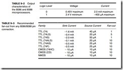
Output Characteristics. Table 9–2 illustrates the output characteristics of all the output pins of these microprocessors. The logic 1 voltage level of the 8086/8088 is compatible with that of most standard logic families, but the logic 0 level is not. Standard logic circuits have a maximum logic 0 voltage of 0.4 V, and the 8086/8088 has a maximum of 0.45 V. Thus, there is a difference of 0.05 V. This difference reduces the noise immunity from a standard level of 400 mV (0.8 V – 0.45 V)

to 350 mV. (The noise immunity is the difference between the logic 0 output voltage and the logic 0 input voltage levels.) The reduction in noise immunity may result in problems with long wire connections or too many loads. It is therefore recommended that no more than 10 loads of any type or combination be connected to an output pin without buffering. If this loading factor is exceeded, noise will begin to take its toll in timing problems.

Table 9–3 lists some of the more common logic families and the recommended fan-out from the 8086/8088. The best choice of component types for the connection to an 8086/8088 output pin is an LS, 74ALS, or 74HC logic component. Note that some of the fan-out currents calculate to more than 10 unit loads. It is therefore recommended that if a fan-out of more than 10 unit loads is required, the system should be buffered.

Pin Connections

AD7–AD0 The 8088 address/data bus lines are the multiplexed address data bus of the 8088 and contain the rightmost 8 bits of the memory address or I/O port number whenever ALE is active (logic 1) or data whenever ALE is inactive (logic 0). These pins are at their high-impedance state during a hold acknowledge.

8086-8088 Hardware Specifications-00028086-8088 Hardware Specifications-0003

A15–A8 The 8088 address bus provides the upper-half memory address bits that are present throughout a bus cycle. These address connections go to their high- impedance state during a hold acknowledge.

AD15–AD8 The 8086 address/data bus lines compose the upper multiplexed address/data bus on the 8086. These lines contain address bits A15–A8 when- ever ALE is a logic 1, and data bus connections D15–D8 when ALE is a logic 0. These pins enter a high-impedance state when a hold acknowledge occurs.

A19/S6–A16/S3 The address/status bus bits are multiplexed to provide address signals A19–A16 and also status bits S6–S3. These pins also attain a high-impedance state during the hold acknowledge.

Status bit S6 is always a logic 0, bit S5 indicates the condition of the IF flag bit, and S4 and S3 show which segment is accessed during the current bus cycle. See Table 9–4 for the truth table of S4 and S3. These two status bits could be used to address four separate 1M byte memory banks by decoding them as A21 and A20.

RD Whenever the read signal is a logic 0, the data bus is receptive to data from the memory or I/O devices connected to the system. This pin floats to its high-impedance state during a hold acknowledge.

READY The READY input is controlled to insert wait states into the timing of the microprocessor. If the READY pin is placed at a logic 0 level, the micro- processor enters into wait states and remains idle. If the READY pin is placed at a logic 1 level, it has no effect on the operation of the microprocessor.

INTR Interrupt request is used to request a hardware interrupt. If INTR is held high when IF = 1, the 8086/8088 enters an interrupt acknowledge cycle (INTA becomes active) after the current instruction has completed execution.

TEST

The Test pin is an input that is tested by the WAIT instruction. If TEST is a logic 0, the WAIT instruction functions as an NOP and if TEST is a logic 1, the WAIT instruction waits for TEST to become a logic 0. The TEST pin is most often connected to the 8087 numeric coprocessor.

NMI The non-maskable interrupt input is similar to INTR except that the NMI interrupt does not check to see whether the IF flag bit is a logic 1. If NMI is activated, this interrupt input uses interrupt vector 2.

RESET The reset input causes the microprocessor to reset itself if this pin is held high for a minimum of four clocking periods. Whenever the 8086 or 8088 is reset, it begins executing instructions at memory location FFFFOH and dis- ables future interrupts by clearing the IF flag bit.

CLK The clock pin provides the basic timing signal to the microprocessor. The clock signal must have a duty cycle of 33 % (high for one third of the clocking period and low for two thirds) to provide proper internal timing for the 8086/8088.

VCC This power supply input provides a +5.0 V, ±10 % signal to the microprocessor.

GND The ground connection is the return for the power supply. Note that the 8086/8088 microprocessors have two pins labeled GND—both must be connected to ground for proper operation.

MN/MX

The minimum/maximum mode pin selects either minimum mode or maximum mode operation for the microprocessor. If minimum mode is selected, the MN/MX pin must be connected directly to +5.0 V.

BHE S7 The bus high enable pin is used in the 8086 to enable the most-significant data bus bits (D15–D8) during a read or a write operation. The state of S7 is always a logic 1.

Minimum Mode Pins. Minimum mode operation of the 8086/8088 is obtained by connecting the MN/MX pin directly to +5.0 V. Do not connect this pin to +5.0 V through a pull-up register, or it will not function correctly.

IO/M or M/ IO

WR

INTA

The IO/M (8088) or the M/ IO (8086) pin selects memory or I/O. This pin indicates that the microprocessor address bus contains either a memory address or an I/O port address. This pin is at its high-impedance state dur- ing a hold acknowledge.

The write line is a strobe that indicates that the 8086/8088 is outputting data to a memory or I/O device. During the time that the WR is a logic 0, the data bus contains valid data for memory or I/O. This pin floats to a high- impedance during a hold acknowledge.

The interrupt acknowledge signal is a response to the INTR input pin. The INTA pin is normally used to gate the interrupt vector number onto the data bus in response to an interrupt request.

ALE Address latch enable shows that the 8086/8088 address/data bus contains address information. This address can be a memory address or an I/O port number. Note that the ALE signal does not float during a hold acknowledge.

DT/ R

The data transmit/receive signal shows that the microprocessor data bus is transmitting (DT/R 1) or receiving (DT/R 0) data. This signal is used to enable external data bus buffers.

DEN Data bus enable activates external data bus buffers.

HOLD The hold input requests a direct memory access (DMA). If the HOLD sig- nal is a logic 1, the microprocessor stops executing software and places its address, data, and control bus at the high-impedance state. If the HOLD pin is a logic 0, the microprocessor executes software normally.

HLDA Hold acknowledge indicates that the 8086/8088 has entered the hold state.

SS0

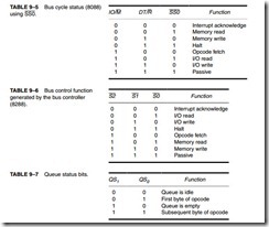
The SS0 status line is equivalent to the S0 pin in maximum mode operation of the microprocessor. This signal is combined with IO/M and DT/R to decode the function of the current bus cycle (see Table 9–5).

Maximum Mode Pins. In order to achieve maximum mode for use with external coprocessors, connect the MN/MX pin to ground.

S2, S1, and S0

The status bits indicate the function of the current bus cycle. These signals are normally decoded by the 8288 bus controller described later in this chapter. Table 9–6 shows the function of these three status bits in the maximum mode.

RQ /GT1 and The request/grant pins request direct memory accesses (DMA) during RQ>GT0 maximum mode operation. These lines are bidirectional and are used to both request and grant a DMA operation.

8086-8088 Hardware Specifications-0004

LOCK

The lock output is used to lock peripherals off the system. This pin is activated by using the LOCK: prefix on any instruction.

QS1 and QS0 The queue status bits show the status of the internal instruction queue.

These pins are provided for access by the numeric coprocessor (8087). See Table 9–7 for the operation of the queue status bits.


8086/8088 HARDWARE SPECIFICATIONS:CLOCK GENERATOR (8284A).

CLOCK GENERATOR (8284A)

This section describes the clock generator (8284A) and the RESET signal, and introduces the READY signal for the 8086/8088 microprocessors. (The READY signal and its associated circuitry are treated in detail in Section 9–5.)

The 8284A Clock Generator

The 8284A is an ancillary component to the 8086/8088 microprocessors. Without the clock gen- erator, many additional circuits are required to generate the clock (CLK) in an 8086/8088-based system. The 8284A provides the following basic functions or signals: clock generation, RESET synchronization, READY synchronization, and a TTL-level peripheral clock signal. Figure 9–2 illustrates the pin-out of the 8284A clock generator.

8086-8088 Hardware Specifications-0005

Pin Functions. The 8284A is an 18-pin integrated circuit designed specifically for use with the 8086/8088 microprocessor. The following is a list of each pin and its function.

AEN1 and AEN2
The address enable pins are provided to qualify the bus ready signals, RDY1 and RDY2, respectively. Section 9–5 illustrates the use of these two pins, which are used to cause wait states, along with the RDY1 and RDY2 inputs. Wait states are generated by the READY pin of the 8086/8088 microprocessors, which is controlled by these two inputs.

RDY1 and RDY2 The bus ready inputs are provided, in conjunction with the AEN1 and AEN2 pins, to cause wait states in an 8086/8088-based system.

ASYNC

The ready synchronization selection input selects either one or two stages of synchronization for the RDY1 and RDY2 inputs.

READY Ready is an output pin that connects to the 8086/8088 READY input. This signal is synchronized with the RDY1 and RDY2 inputs.

X1 and X2 The crystal oscillator pins connect to an external crystal used as the timing source for the clock generator and all its functions.

F/C

The frequency/crystal select input chooses the clocking source for the 8284A. If this pin is held high, an external clock is provided to the EFI input pin; if it is held low, the internal crystal oscillator provides the timing signal. The external frequency input is used when the F/C pin is pulled high. EFI supplies the timing whenever the F/C pin is high.

CLK The clock output pin provides the CLK input signal to the 8086/8088 microprocessors and other components in the system. The CLK pin has an output signal that is one third of the crystal or EFI input frequency, and has a 33% duty cycle, which is required by the 8086/8088.

PCLK The peripheral clock signal is one sixth the crystal or EFI input frequency, and has a 50% duty cycle. The PCLK output provides a clock signal to the peripheral equipment in the system.

OSC The oscillator output is a TTL-level signal that is at the same frequency as the crystal or EFI input. The OSC output provides an EFI input to other 8284A clock generators in some multiple-processor systems.

RES

The reset input is an active-low input to the 8284A. The RES pin is often connected to an RC network that provides power-on resetting.

RESET The reset output is connected to the 8086/8088 RESET input pin.

CSYNC The clock synchronization pin is used whenever the EFI input provides synchronization in systems with multiple processors. If the internal crystal oscillator is used, this pin must be grounded.

GND The ground pin connects to ground.

VCC This power supply pin connects to +5.0 V with a tolerance of ±10%.

8086-8088 Hardware Specifications-0006

Operation of the 8284A

The 8284A is a relatively easy component to understand. Figure 9–3 illustrates the internal tim- ing diagram of the 8284A clock generator.

Operation of the Clock Section. The top half of the logic diagram represents the clock and synchronization section of the 8284A clock generator. As the diagram shows, the crystal oscillator has two inputs: X1 and X2. If a crystal is attached to X1 and X2, the oscillator generates a square- wave signal at the same frequency as the crystal. The square-wave signal is fed to an AND gate and also to an inverting buffer that provides the OSC output signal. The OSC signal is sometimes used as an EFI input to other 8284A circuits in a system.

An inspection of the AND gate reveals that when F/C is a logic 0, the oscillator output is steered through to the divide-by-3 counter. If F/C is a logic 1, then EFI is steered through to the counter.

The output of the divide-by-3 counter generates the timing for ready synchronization, a signal for another counter (divide-by-2), and the CLK signal to the 8086/8088 microprocessor. The CLK signal is also buffered before it leaves the clock generator. Notice that the output of the first counter feeds the second. These two cascaded counters provide the divide-by-6 output at PCLK, the peripheral clock output.

clip_image018Figure 9–4 shows how an 8284A is connected to the 8086/8088. Notice that F/C and CSYNC are grounded to select the crystal oscillator, and that a 15 MHz crystal provides the nor- mal 5 MHz clock signal to the 8086/8088, as well as a 2.5 MHz peripheral clock signal.

Operation of the Reset Section. The reset section of the 8284A is very simple: It consists of a Schmitt trigger buffer and a single D-type flip-flop circuit. The D-type flip-flop ensures that the timing requirements of the 8086/8088 RESET input are met. This circuit applies the RESET signal to the microprocessor on the negative edge (1-to-0 transition) of each clock. The 8086/8088 microprocessors sample RESET at the positive edge (0-to-1 transition) of the clocks; therefore, this circuit meets the timing requirements of the 8086/8088.

Refer to Figure 9–4. Notice that an RC circuit provides a logic 0 to the RES input pin when power is first applied to the system. After a short time, the RES input becomes a logic 1 because the capacitor charges toward +5.0 V through the resistor. A pushbutton switch allows the microprocessor to be reset by the operator. Correct reset timing requires the RESET input to come a logic 1 no later than four clocks after system power is applied, and to be held high for at

8086-8088 Hardware Specifications-0007

least 50 μs. The flip-flop makes certain that RESET goes high in four clocks, and the RC time constant ensures that it stays high for at least 50 μs.


QUESTIONS AND PROBLEMS ON PROGRAMMING THE MICROPROCESSOR.

QUESTIONS AND PROBLEMS

1. The assembler converts a source file to a(n) file.

2. What files are generated from the source file TEST.ASM if it is processed by ML.EXE?

3. The linker program links object files and files to create an execution file.

4. What does the PUBLIC directive indicate when placed in a program module?

5. What does the EXTRN directive indicate when placed in a program module?

6. What directive appears with labels defined as external?

7. Describe how a library file works when it is linked to other object files by the linker program.

8. What assembler language directives delineate a macro sequence?

9. What is a macro sequence?

10. How are parameters transferred to a macro sequence?

11. Develop a macro called ADD32 that adds the 32-bit contents of DX-CX to the 32-bit con- tents of BX-AX.

12. How is the LOCAL directive used within a macro sequence?

13. Develop a macro called ADDLIST PARA1,PARA2 that adds the contents of PARA1 to PARA2. Each of these parameters represents an area of memory. The number of bytes added are indicated by register CX before the macro is invoked.

14. Develop a macro that sums a list of byte-sized data invoked by the macro ADDM LIST,LENGTH. The label LIST is the starting address of the data block and LENGTH is the number of data added. The result must be a 16-bit sum found in AX at the end of the macro sequence.

15. What is the purpose of the INCLUDE directive?

16. Modify the function in Example 8–12 so that it filters the numbers 0 through 9 from only the keyboard and not the keypad and ignores all other characters.

17. Modify the function in Example 8–12 so that it generates a random 8-bit number in class variable char Random. (Hint: To accomplish this, increment Random each time that the KeyDown function is called.)

18. Modify the software you developed in question 17 so that it generates a random number between 9 and 62.

19. Modify the function listed in Example 8–15 so that the hexadecimal numbers use lowercase letters a through f instead of the uppercase letters.

20. Modify Example 8–16 so it will shift/rotate left or right. This is accomplished by adding a pair of radio buttons to select the direction.

21. What event handlers are used to access the mouse in the Visual C++ programming environ- ment and what event causes each handler to be called?

22. How is the right mouse button detected in a program?

23. How is a double-click detected with the mouse?

24. Develop software that detects when both the right and left mouse buttons are pressed simultaneously.

25. How is a color selected in a program using Visual C++?

26. What is the purpose of the ForeColor property?

27. When a number is converted from binary to BCD, the instruction accomplishes the conversion, provided the number is less than 100 decimal.

28. How is a large number (over 100 decimal) converted from binary to BCD?

29. How could a binary number be displayed as an octal number?

30. A BCD digit is converted to ASCII code by adding a(n) .

31. An ASCII-coded number is converted to BCD by subtracting .

32. Develop a function that reads an ASCII number from a textbox control as keys are typed (use KeyDown) on the keyboard and returns it as an unsigned int. The number in the textbox is an octal number that is converted to binary by the function.

33. Explain how a three-digit ASCII-coded number is converted to binary.

34. Develop a function that converts all lowercase ASCII-coded letters into uppercase ASCII- coded letters. Your procedure may not change any other character except the letters a–z and must return the converted character as a char.

35. Develop a lookup table that converts hexadecimal data 00H–0FH into the ASCII-coded characters that represent the hexadecimal digits. Make sure to show the lookup table and any software required for the conversion. It is suggested that a function is created to perform the conversion.

36. Explain the purpose of a boot sector, FAT, and root directory in the FAT system.

37. Explain the purpose of the MFT in the NTFS file system.

38. The surface of a disk is divided into tracks that are further subdivided into .

39. What is a bootstrap loader and where is it found?

40. What is a cluster?

41. The NTFS file system often uses cluster of bytes in length.

42. What is the maximum length of a file?

43. What code is used to store the name of a file when long file names are in use?

44. DOS file names are at most characters in length.

45. How many characters normally appear in an extension?

46. How many characters may appear in a long file name?

47. Develop a program that opens a file called TEST.LST, reads 512 bytes from the file into memory area Array, and closes the file.

48. Show how to rename file TEST.LST to TEST.LIS.

49. What is the purpose of the File Move member function?

50. What is a control?

51. Write a program that reads any decimal number between 0 and 2G and displays the 32-bit binary version on the video display.

52. Write a program that displays the binary powers of 2 (in decimal) on the video screen for the powers 0 through 7. Your display shows 2n = value for each power of 2.

53. Using a timer to generate a random number, develop a program that displays random num- bers between 1 and 47 (or whatever) for your state’s lottery.

54. Modify the program in Example 8–28 so it also displays the letters A, b, C, d, E, and F for a hexadecimal seven-segment display.

55. Modify Example 8–42 to encrypt the message using an algorithm of your own design.

56. Develop a Decryption function (for a String) to accompany the encryption of question 55.


SUMMARY OF PROGRAMMING THE MICROPROCESSOR.

SUMMARY

1. The assembler program (ML.EXE) assembles modules that contain PUBLIC variables and segments, plus EXTRN (external) variables. The linker program (LINK.EXE) links modules and library files to create a run-time program executed from the DOS command line. The run-time program usually has the extension EXE, but might contain the extension COM.

2. The MACRO and ENDM directives create a new opcode for use in programs. These macros are similar to procedures, except that there is no call or return. In place of them, the assembler inserts the code of the macro sequence into a program each time it is invoked. Macros can include variables that pass information and data to the macro sequence.

3. Setting focus to an object is accomplished by using the Focus( ) member variable found with most objects.

4. The Convert class in C++ is used to convert from one form to another in many cases, but not in all cases.

5. The mouse driver is accessed from Windows by installing handlers for various Windows events such as Mouse Move, Mouse Down, etc.

6. Conversion from binary to BCD is accomplished with the AAM instruction for numbers that are less than 100 or by repeated division by 10 for larger numbers. Once the number is converted to BCD, 30H is added to convert each digit to ASCII code for placement in a string.

7. When converting from an ASCII number to BCD, 30H is subtracted from each digit. To obtain the binary equivalent, multiply by 10 and then add each new digit.

8. Lookup tables are used for code conversion with the XLAT instruction if the code is an 8-bit code. If the code is wider than 8 bits, a short procedure that accesses a lookup table provides the conversion. Lookup tables are also used to hold addresses so that different parts of a pro- gram or different procedures can be selected.

9. Conditional assembly language statements allow portions of a program to be assembled if a condition is met. These are useful for tailoring software to an application. In Visual C++ Express, a program that contains assembly code must be compiled with the /CLR switch.

10. The disk, memory system contains tracks that hold information stored in sectors. Many disk systems store 512 bytes of information per sector. Data on the disk are organized in a boot sector, file allocation table, root directory, and data storage area. The boot sector loads the DOS system from the disk into the computer memory system. The FAT or MFT indicates which sectors are present and whether they contain data. The root directory contains file names and subdirectories through which all disk files are accessed. The data storage area contains all subdirectories and data files.

11. Files are manipulated with the File object in Visual C++. To read a disk file, the file must be opened, read, and then closed. To write to a disk file, it must be opened, written, and then closed. When a file is opened, the file pointer addresses the first byte of the file. To access data at other locations, the file pointer is moved using a Seek before data are read or written.

12. A sequential access file is a file that is accessed sequentially from the beginning to the end.

A random access file is a file that is accessed at any point. Although all disk files are sequential, they can be treated as random access files by using software.


PROGRAMMING THE MICROPROCESSOR:EXAMPLE PROGRAMS

EXAMPLE PROGRAMS

Now that many of the basic programming building blocks have been discussed, we present some example application programs. Although these example programs may seem trivial, they show some additional programming techniques and illustrate programming styles for the microprocessor.

Time/Date Display Program

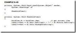
Although this program does not use assembly language, it does demonstrate how to obtain the date and time from the Windows API and how to format it for display. It also illustrates how to use a timer in Visual C++. Example 8–40 illustrates a program that uses a timer, set to interrupt the program once per second, to display the time and date. The time and date are obtained by using DateTime object to read the computer time and date into a variable called dt. The format member TimeDate is used to format the dt variable. Create a dialog application called DateTime and place two labels on it as shown in Figure 8–13.

Programming the Microprocessor-0337Programming the Microprocessor-0338

Numeric Sort Program

At times, numbers must be sorted into numeric order. This is often accomplished with a bubble sort. Figure 8–14 shows five numbers that are sorted with a bubble sort. Notice that the set of five numbers is tested four times with four passes. For each pass, two consecutive numbers are com- pared and sometimes exchanged. Also notice that during the first pass there are four comparisons, during the second three, and so forth.

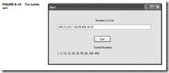
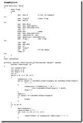
Example 8–41 illustrates a program that accepts 10 numbers from the keyboard (32-bit integers). After these 32-bit numbers are accepted and stored in memory section numbers, they are sorted by using the bubble-sorting technique. This bubble sort uses a swap flag to determine whether any numbers were exchanged in a pass. If no numbers were exchanged, the numbers are in order and the sort terminates. This early termination normally increases the efficiency of the sort because numbers are rarely completely out of order.

Once the numbers are sorted, they are displayed in ascending order. Figure 8–15 shows how the application appears after it is executed.

Programming the Microprocessor-0339Programming the Microprocessor-0340Programming the Microprocessor-0341

Data Encryption

Data encryption seems to be the vogue at this time because of the security aspect of many systems. To illustrate simple data encryption for a character string, suppose that each character in a string is exclusive-ORed with a number called an encryption key. This certainly changes the code of the character, but to make it a bit more random, suppose that the encryption key is changed after each character is encrypted. In this way patterns are much harder to detect in the encrypted message, making it harder to decipher.

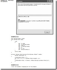
To illustrate this simple scheme, Figure 8–16 shows a screen shot of the program to test the scheme, using a textbox control to accept a character string and a label to display the encrypted message. This example was generated using an initial encryption key of 0×45. If the initial value is changed, the encrypted message will change.

Example 8–42 lists the program used to generate the message in its encrypted form in a rich textbox control. The button event handler reads the contents of the textbox control, used for entering the character string to be encrypted, and uses a short assembly language function to encrypt the string. Notice how the program uses assembly language to Exclusive-OR each character of the string with the EncryptionKey and then how the EncryptionKey is modified for the next character. The technique used here increments the Encryption key and prevents the key from becoming larger than 7FH. This technique can be made more intricate to make it even more difficult to decipher. For example, suppose that the key is incremented on every other character and that is alternated with inverting the key, as shown in Example 8–43. Almost any combination of operations can be used to modify the key between passes to make it very difficult to decode. In practice we use a 128-bit key and the technique for modification is different, but nonetheless, this is basically how encryption is performed. Because Example 8–40 uses an 8-bit key, the encrypted message could be cracked by trying all 256 (28) possible keys, but if a 128-bit key is used, it requires far many more attempts (2128) to crack—an almost impossible number of attempts.

Programming the Microprocessor-0342Programming the Microprocessor-0343


PROGRAMMING THE MICROPROCESSOR:DISK FILES

DISK FILES

Data are found stored on the disk in the form of files. The disk itself is organized in four main parts: the boot sector, the file allocation table (FAT), the root directory, and the data storage areas. The Windows NTFS (New Technology File System) contains a boot sector and a master file table (MFT). The first sector on the disk is the boot sector, which is used to load the disk operating system (DOS) from the disk into the memory when power is applied to the computer.

The FAT (or MFT) is where the names of files/subdirectories and their locations on the disk are stored by the operating system. All references to any disk file are handled through the FAT (or MFT). All other subdirectories and files are referenced through the root directory in the FAT system. The NTFS system does not have a root directory even though the file system may still appear to have a root directory. The disk files are all considered sequential access files, meaning that they are accessed a byte at a time, from the beginning of the file toward the end. Both the NTFS file system and the FAT file system are in use, with the hard disk drive on most modern Windows systems using NTFS and the floppy disk, CD-ROM, and DVD using the FAT system.

Disk Organization

Figure 8–7 illustrates the organization of sectors and tracks on the surface of the disk. This organization applies to both floppy and hard disk memory systems. The outer track is always track 0, and the inner track is 39 (double density) or 79 (high density) on floppy disks. The inner track on a hard disk is determined by the disk size, and could be 10,000 or higher for very large hard disks.

Figure 8–8 shows the organization of data on a disk. The length of the FAT is determined by the size of the disk. In the NTFS system, the length of the MFT is determined by the number

Programming the Microprocessor-0314

Programming the Microprocessor-0315

of files stored on the disk. Likewise, the length of the root directory, in a FAT volume, is deter- mined by the number of files and subdirectories located within it. The boot sector is always a single 512-byte-long sector located in the outer track at sector 0, the first sector.

The boot sector contains a bootstrap loader program that is read into RAM when the sys- tem is powered. The bootstrap loader then executes and loads the operating system into RAM. Next, the bootstrap loader passes control to the operating system program, allowing the computer to be under the control of and execute Windows, in most cases. This same sequence of events also occurs if the Linux operating system is found on the disk.

The FAT indicates which sectors are free, which are corrupted (unusable), and which contain data. The FAT table is referenced each time that the operating system writes data to the disk so that it can find a free sector. Each free cluster is indicated by 0000H in the FAT and each occupied sector is indicated by the cluster number. A cluster can be anything from one sector to any number of sectors in length. Many hard disk memory systems use four sectors per cluster, which means that the smallest file is 512 bytes × 4, or 2048 bytes long. In a system that uses NTFS, the cluster size is usually 4K bytes, which is eight sectors long.

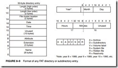
Figure 8–9 shows the format of each directory entry in the root, or in any other directory or subdirectory. Each entry contains the name, extension, attribute, time, date, location, and length. The length of the file is stored as a 32-bit number. This means that a file can have a maximum length of 4G bytes. The location is the starting cluster number.

Windows NTFS uses a much larger directory entry or record (1,024 bytes) than that of the FAT system (32 bytes). The MFT record contains the file name, file date, attribute, and data. The data can be the entire contents of the file, or a pointer to where the data is stored on the disk called a file run. Generally files that are smaller than about 1500 bytes fit into the MFT record. Longer files fit into a file run or file runs. A file run is a series of contiguous clusters that store the file data. Figure 8–10 illustrates an MFT record in the Windows NTFS file system. The information attribute contains the create date, last modification date, create time, last modification time, and file attributes such as read-only, archive, and so forth. The security attribute stores all security information for the file for limiting access to the file in the Windows system. The header stores information about the record type, size, name (optional), and whether it is resident or not.

File Names

Files and programs are stored on a disk and referenced both by a file name and an extension to the file name. With the DOS operating system, the file name may only be from one to eight characters long. The file name contains just about any ASCII character, except for spaces or the “ . / [ ] * , : < > I ; ? = characters. In addition to the file name, the file can have an optional
Programming the Microprocessor-0316

one- to three-digit extension to the file name. Note that the name of a file and its extension are always separated by a period. If Windows 95 through Windows XP is in use, the file name can be of any length (up to 255 characters) and can even contain spaces. This is an improvement over the eight-character file name limitation of DOS. Also note that a Windows file can have more than one extension.

Directory and Subdirectory Names. The DOS file management system arranges the data and programs on a disk into directories and subdirectories. In Windows directories and sub- directories are called file folders. The rules that apply to file names also apply to file folder names. The disk is structured so that it contains a root directory when first formatted. The root directory or folder for a hard disk used as drive C is C:. Any other folder is placed in the root directory. For example, C:DATA is folder DATA in the root directory. Each folder placed in the root directory can also have subdirectories or subfolders. Examples are the subfolders C:DATAAREA1 and C:DATAAREA2, in which the folder DATA contains two subfolders: AREA1 and AREA2. Subfolders can also have additional subfolders. For example, C:DATAAREA2LIST depicts folder DATA, subfolder AREA, which contains a subfolder called LIST.

Sequential Access Files

All DOS files and Windows files are sequential files. A sequential file is stored and accessed from the beginning of the file toward the end, with the first byte and all bytes between it and the last accessed to read the last byte. Fortunately, files are read and written in C++ using the File class, which makes their access and manipulation easy. This section of the text describes how to

Programming the Microprocessor-0317

create, read, write, delete, and rename a sequential access file. To gain access to the File class, a new using must be added to the list of using statements at the top of the program. If file access is needed, add a using namespace System::IO; statement to the program.

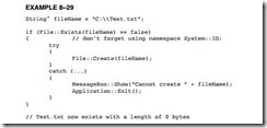
File Creation. Before a file can be used, it must exist on the disk. A file is created by the File class using Create as an attribute that directs File to create a file. A file is created with create as illustrated in Example 8–29. Here the name of the file that is created by the program is stored in a Stringˆ called File Name. Next, the File class is used to test and see if the file already exists before creating it. Finally, in the if statement the file is created.

In this example, if the file fails to open because the disk is full or the folder is not found, a Windows message box displays Cannot create file followed by the file name, and an exit from the program occurs when OK is clicked in the message box. To try this example, create a dialog application and place the code in the Load event handler. Choose a folder name that does not exist (test should probably work) and run the application. You should see the error message. If you change the File Name so it does not include the folder, you will not get the error message.
Programming the Microprocessor-0318

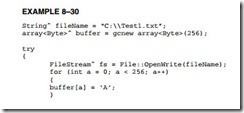
Writing to a File. Once a file exists, it can be written to. In fact, it would be highly unusual to create a file without writing something to it. Data are written to a file one byte at a time. The FileStream class is used to write a stream of data to the file. Data are always written starting at the very first byte in a file. Example 8–30 lists a program that creates a file in the root directory called Test1.txt and stores the letter A in each of its 256 bytes. If you execute this code and look at Test1.txt with Note  Pad, you will see a file filled with 256 letter As. Note that the file stream should be closed when finished using Close( ) function. Also notice in this example that an array of size byte is created using the garbage collection class in C++. It is important to use this class to create a managed array of data.
Programming the Microprocessor-0319Programming the Microprocessor-0320

Suppose that a 32-bit integer must be written to a file. Because only bytes can be written, a method must be used to convert the four bytes of the integer into a form that can be written to a file. In C++ shifts are used to place the byte into the proper location to store in the array. Assembly language can also accomplish the same task in fewer bytes, as listed in Example 8–31. If you look at the assembly code for each method, you see that the assembly language method is much shorter and much faster. If speed and size are important, then the assembly code is by far the best choice, although in this case the code generated by C++ is fairly efficient.

Programming the Microprocessor-0321

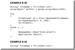
Reading File Data. File data are read from the beginning of the file toward the end using the Open Read member of File. Example 8–32 shows an example that reads the file written in Example 8–30 into a buffer called buffer1. The Open Read function returns the number of bytes actually read from the file, but not used in this example. This works fine if the size of the file is known as it is here, but suppose that the length of the file is not known. The File Info class is used to find the length of a file as illustrated in Example 8–33.
Programming the Microprocessor-0322Programming the Microprocessor-0323

An Example Binary Dump Program. One tool not available with Windows is a program that displays the contents of a file in hexadecimal code. Although this may not be used by most pro- grammers, it is used whenever software is developed so that the actual contents of a file can be viewed in hexadecimal format. Start a forms application in Windows and call it HexDump. Place a control called a Rich Textbox onto the form as illustrated in Figure 8–11. Under Properties for the Rich Textbox Control, make sure you change Locked to true and Scroll bars to Vertical. If you display a very large file, you will want to be able to scroll down through the code. Very large files take some time to load in this program.

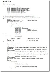
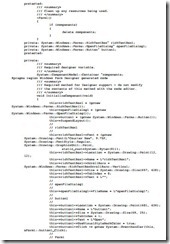
This program uses the function (Disph) shown earlier in Example 8–24 to display the address as an eight-digit hexadecimal address and also to display the contents of the address in hexadecimal form as a two-digit number. Add Disph function to the program so it returns a String at the location addressed by char temp as the third parameter. The first two parameters contain two integers: one for the number and one for the number of digits called size, as shown in Example 8–34.

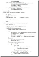
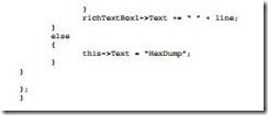
Example 8–34 shows the entire program required to perform a hexadecimal dump. Most of the program is generated by Visual C++, only the function at the top and a few at the end were entered to create the application. Note that to change the file for this program requires a change of the name of the file in the program. This can be modified by using an edit box to enter the file name, but it was not done in this example for sake of brevity. In this program 16 bytes are read at a time and formatted for display. This process continues until no bytes remain in the file. The

ASCII data that are displayed at the end of the hexadecimal listing are filtered so that any ASCII character under 32 (a space) are displayed as a period. This is important or control characters such as line feed, backspace, and the like will destroy the screen formatting of the ASCII text, and that is undesirable.
Programming the Microprocessor-0324Programming the Microprocessor-0325Programming the Microprocessor-0326Programming the Microprocessor-0327

The File Pointer and Seek. When a file is opened, written, or read, the file pointer addresses the current location in the sequential file. When a file is opened, the file pointer always addresses the first byte of the file. If a file is 1024 bytes long, and a read function reads 1023 bytes, the file pointer addresses the last byte of the file, but not the end of the file.

The file pointer is a 32-bit number that addresses any byte in a file. The File Append member function is used to add new information to the end of a file. The file pointer can be moved from the start of the file or from the end of the file. Open moves the pointer to the start of the file. In practice, both are used to access different parts of the file. The FileStream member function Seek allows the file pointer to be moved to the start of a file (SeekOrigin::Begin), the end of a file (SeekOrigin::End), or the current location in the file (SeekOrigin::Current). The first number in the Seek function is the offset. If the third byte in the file is accessed, it is accessed with a Seek(2, SeekOrigin::Begin) function. (The third byte is at offset 2.) Note that the second number in the Write function is also an offset and can be used in the same manner as a Seek.

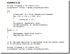
Suppose that a file exists on the disk and that you must append the file with 256 bytes of new information. When the file is opened, the file pointer addresses the first byte of the file. If you attempt to write without moving the file pointer to the end of the file, the new data will overwrite the first 256 bytes of the file. Example 8–35 shows a sequence of instructions for Appends, which adds 256 bytes of data to the end of the file, and then closes the file. This file is appended with 256 new bytes of data from area Buffer.
Programming the Microprocessor-0328Programming the Microprocessor-0329

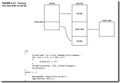
One of the more difficult file maneuvers is inserting new data in the middle of the file. Figure 8–12 shows how this is accomplished by creating a second file. Notice that the part of the file before the insertion point is copied into the new file. This is followed by the new information before the remainder of the file is appended after the insertion in the new file. Once the new file is complete, the old file is deleted and the new file is renamed to the old file name.

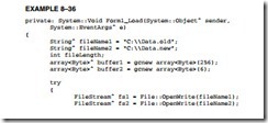
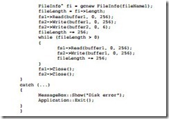
Example 8–36 shows a program that inserts new data into an old file. This program copies the Data.new file into the Data.old file at a point after the first 256 bytes of the Data.old file. The new data from buffer2 is next added to the file and then this is followed by the remainder of the old file. New File member functions are used to delete the old file and rename the new file to the old file name.
Programming the Microprocessor-0330Programming the Microprocessor-0331

Random Access Files

Random access files are developed through software using sequential access files. A random access file is addressed by a record number rather than by going through the file searching for data. The Seek function becomes very important when random access files are created. Random access files are much easier to use for large volumes of data, which are often called databases.

Creating a Random Access File. Planning is paramount when creating a random access file system. Suppose that a random access file is required for storing the names of customers. Each customer record requires 32 bytes for the last name, 32 bytes for the first name, and one byte for the middle initial. Each customer record contains two street address lines of 64 bytes each, a city line of 32 bytes, two bytes for the state code, and nine bytes for the Zip Code. The basic customer information alone requires 236 bytes; additional information expands the record to 512 bytes. Because the business is growing, provisions are made for 5000 customers. This means that the total random access file is 2,560,000 bytes long.

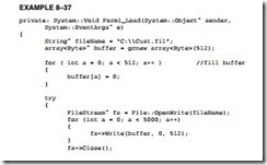
Example 8–37 illustrates a short program that creates a file called CUST.FIL and inserts 5000 blank records of 512 bytes each. A blank record contains 00H in each byte. This appears be a large file, but it fits on the smallest of hard disks.
Programming the Microprocessor-0332Programming the Microprocessor-0333

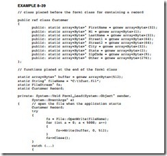
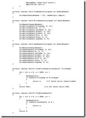
Reading and Writing a Record. Whenever a record must be read, the record number is found by using a Seek. Example 8–38 lists a function that is used to Seek to a record. This function assumes that a file has been opened as CustomerFile and that the CUST.FIL remains open at all times.

Notice how the record number is multiplied by 512 to obtain a count to move the file pointer using a Seek. In each case, the file pointer is moved from the start of the file to the desired record.
Programming the Microprocessor-0334Programming the Microprocessor-0335Programming the Microprocessor-0336


PROGRAMMING THE MICROPROCESSOR:DATA CONVERSIONS.

DATA CONVERSIONS

In computer systems, data are seldom in the correct form. One main task of the system is to convert data from one form to another. This section of the chapter describes conversions between binary and ASCII data. Binary data are removed from a register or memory and converted to ASCII for the video display. In many cases, ASCII data are converted to binary as they are typed on the keyboard. We also explain converting between ASCII and hexadecimal data.

Converting from Binary to ASCII

Conversion from binary to ASCII is accomplished in three ways: (1) by the AAM instruction if the number is less than 100 (provided the 64-bit extensions are not used for the conversion), (2) by a series of decimal divisions (divide by 10), or (3) by using the C++ Convert class function ToString. Techniques 1 and 2 are presented in this section.

The AAM instruction converts the value in AX into a two-digit unpacked BCD number in AX. If the number in AX is 0062H (98 decimal) before AAM executes, AX contains 0908H after AAM executes. This is not ASCII code, but it is converted to ASCII code by adding 3030H to AX. Example 8–20 illustrates a program that uses the procedure that processes the binary value in AL (0–99) and displays it on the video screen as a decimal number. The procedure blanks a leading zero, which occurs for the numbers 0–9, with an ASCII space code. This example pro- gram displays the number 74 (testdata) on the video screen. To implement this program, create a forms-based application in Visual C++ and place a single label called label1 on the form. The number 74 will appear if the assembly language function in Example 8–20 is placed at the top of the program after the last using statement and the project is changed to a /CLR program. The call to the assembly language function is placed in the Load event handler for the form.

Programming the Microprocessor-0302

The reason that AAM converts any number between 0 and 99 to a two-digit unpacked BCD number is because it divides AX by 10. The result is left in AX so AH contains the quotient and AL the remainder. This same scheme of dividing by 10 can be expanded to convert any whole number of any number system (if the divide-by number is changed) from binary to an ASCII-coded character string that can be displayed on the video screen. For example, if AX is divided by 8 instead of 10, the number is displayed in octal.

The algorithm (called Horner’s algorithm) for converting from binary to decimal ASCII code is:

1. Divide by 10, then save the remainder on the stack as a significant BCD digit.

2. Repeat step 1 until the quotient is a 0.

3. Retrieve each remainder and add 30H to convert to ASCII before displaying or printing.

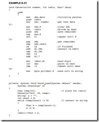
Example 8–21 shows how the unsigned 32-bit number is converted to ASCII and displayed on the video screen. Here, we divide EAX by 10 (for decimal) and save the remainder on the stack after each division for later conversion to ASCII. After all the digits have been converted, the result is displayed on the video screen by removing the remainders from the stack and converting them to ASCII code. This program also blanks any leading zeros that occur. As mentioned, any number base can be used by changing the radix variable in this example. Again, to implement this example create a forms application with the /CLR option and a single label called label1. If the number base is greater than 10, letters are used for the representation of characters beyond 9. The software functions from base 2 to base 36.

Programming the Microprocessor-0303

Converting from ASCII to Binary

Conversions from ASCII to binary usually start with keyboard entry. If a single key is typed, the conversion occurs when 30H is subtracted from the number. If more than one key is typed, conversion from ASCII to binary still requires 30H to be subtracted, but there is one additional step. After subtracting 30H, the number is added to the result after the prior result is first multiplied by 10.

The algorithm for converting from ASCII to binary is:

1. Begin with a binary result of 0.

2. Subtract 30H from the character to convert it to BCD.

3. Multiply the result by 10, and then add the new BCD digit.

4. Repeat steps 2 and 3 for each character of the number.

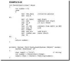
Example 8–22 illustrates a program that implements this algorithm. Here, the binary number is displayed from variable temp on label1 using the Convert class to convert it to a string. Each time this program executes, it reads a number from the char variable array numb and converts it to binary for display on the label.

Programming the Microprocessor-0304

Displaying and Reading Hexadecimal Data

Hexadecimal data are easier to read from the keyboard and display than decimal data. These types of data are not used at the application level, but at the system level. System-level data are often hexadecimal, and must either be displayed in hexadecimal form or read from the keyboard as hexadecimal data.

Reading Hexadecimal Data. Hexadecimal data appear as 0 to 9 and A to F. The ASCII codes obtained from the keyboard for hexadecimal data are 30H to 39H for the numbers 0 through 9, and 41H to 46H (A–F) or 61H to 66H (a–f) for the letters. To be useful, a pro- gram that reads hexadecimal data must be able to accept both lowercase and uppercase letters as well as numbers.

Example 8–23 shows two functions: One (Conv) converts the contents of an unsigned char from ASCII code to a single hexadecimal digit, and the other (Readh) converts a String with up to eight hexadecimal digits into a numeric value that is returned as a 32-bit unsigned integer. This example illustrates a balanced mixture of C++ and assembly language to perform the conversion.

Programming the Microprocessor-0305

Displaying Hexadecimal Data. To display hexadecimal data, a number must be divided into 2-, 4-, or 8-bit sections that are converted into hexadecimal digits. Conversion is accomplished by adding 30H to the numbers 0 to 9 or 37H to the letters A to F for each section.

A function (Disph) stores a string of the contents of the unsigned integer parameter passed to the function. This function converts the unsigned into a two-, four-, or eight-digit character string as selected by parameter size. The function is listed in Example 8–24. Disph(number, 2) converts an unsigned integer number into a two-digit hexadecimal String, where Disph(number, 4) converts it to a four-digit hexadecimal string and Disph(number, 8) converts to an eight-digit hexadecimal character string.

Programming the Microprocessor-0306

Using Lookup Tables for Data Conversions

Lookup tables are often used to convert data from one form to another. A lookup table is formed in the memory as a list of data that is referenced by a procedure to perform conversions. In many lookup tables, the XLAT instruction is often used to look up data in a table, provided that the table contains 8-bit-wide data and its length is less than or equal to 256 bytes.

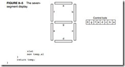
Converting from BCD to Seven-Segment Code. One simple application that uses a lookup table is BCD to seven-segment code conversion. Example 8–25 illustrates a lookup table that contains the seven-segment codes for the numbers 0 to 9. These codes are used with the seven-segment display pictured in Figure 8–5. This seven-segment display uses active high (logic 1) inputs to light a segment. The lookup table code (array temp1) is arranged so that the a segment is in bit position 0 and the g segment is in bit position 6. Bit position 7 is 0 in this example, but it can be used for displaying a decimal point, if required.

Programming the Microprocessor-0307Programming the Microprocessor-0308

The Look Up function, which performs the conversion, contains only a few instructions and assumes that the temp parameter contains the BCD digit (0–9) to be converted to seven- segment code that is returned as an unsigned char. The first instruction addresses the lookup table by loading its address into EBX, and the others perform the conversion and return the seven- segment code as an unsigned char. Here the temp1 array is indexed by the BCD passed to the function in temp.

Using a Lookup Table to Access ASCII Data. Some programming techniques require that numeric codes be converted to ASCII character strings. For example, suppose that you need to display the days of the week for a calendar program. Because the number of ASCII characters in each day is different, some type of lookup table must be used to reference the ASCII-coded days of the week.

The program in Example 8–26 shows a table, formed as an array, which references ASCII-coded character strings. Each character string contains an ASCII-coded day of the week. The table contains references to each day of the week. The function that accesses the day of the week uses the day parameter, with the numbers 0 to 6 to refer to Sunday through Saturday. If day contains a 2 when this function is invoked, the word Tuesday is displayed on the video screen. Please note that this function does not use any assembly code, since we are merely accessing an element in an array using the day of the week as an index. It is shown so additional uses for arrays can be presented, because they may have application in programs used with embedded microprocessors.

Programming the Microprocessor-0309Programming the Microprocessor-0310

An Example Program Using a Lookup Table

Figure 8–6 shows the screen of a dialog application called Display that displays the a seven- segment-style character on the screen for each numeric key typed on the keyboard. As we learned in prior examples, the keyboard can be intercepted in a Visual C++ program using the Key Down and Key Press handler functions, which is exactly what the program does to obtain the key from the keyboard. Next the code typed is filtered so only 0–9 are accepted and a lookup table is used to access the seven-segment code for display.

The display digit is drawn using panel control objects. The horizontal bars are drawn using dimensions 120 × 25 and the vertical bars are drawn using dimensions 25 × 75. The dimensions of an object appear in the extreme lower right corner of the resource screen in Visual Studio. Make sure that you add the panels in the same order as the display; that is, add label a first, followed by b, and so on, just as in the seven-segment display of Figure 8–5. Use panel1 through panel7 for the variable names of the panels in this application and don’t forget to select a back- ground color of black.

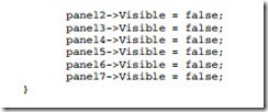
Add the function listed in Example 8–27 called Clear to the program to clear the display. This is used to clear the digit from the screen when the program first executes and also before a new digit is displayed. Notice that the Visible property of the panels is used to hide the digit. An alternate method changes the color of the panel.

Programming the Microprocessor-0311Programming the Microprocessor-0312

Once a key is typed, the Key Down function (see Example 8–28) filters the keystroke and converts the keystroke into seven-segment code using the lookup table. After converting to seven-segment code, the Show Digit function is called to show the digit on the screen. The Show Digit function tests each bit of the seven-segment code and changes the visibility of each panel to display a digit. This program does not use any assembly code for its operation.

Programming the Microprocessor-0313


PROGRAMMING THE MICROPROCESSOR:USING THE KEYBOARD AND VIDEO DISPLAY.

USING THE KEYBOARD AND VIDEO DISPLAY

Today, there are few programs that don’t use the keyboard and video display. This section of the text explains how to use the keyboard and video display connected to the IBM PC or any compatible computer running under Windows.

Reading the Keyboard

The keyboard of the personal computer is read by many different objects available to Visual C++. Data read from the keyboard are either in ASCII-coded or in extended ASCII-coded form. They are then either stored in 8-bit ASCII form or in 16-bit Unicode form. As mentioned in an earlier chapter, Unicode contains ASCII code in the codes 0000H–00FFH. The remaining codes are used for foreign language character sets. Do not use cin or getch to read keys in Visual C++ as we do in a DOS C++ console application; in place of cin or getch we use controls in Visual C++ that accomplish the same task.

Programming the Microprocessor-0284Programming the Microprocessor-0285Programming the Microprocessor-0286

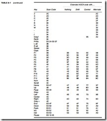
The ASCII-coded data appear as outlined in Table 1–8 in Section 1–4. The extended character set of Table 1–9 applies to printed or displayed data only, and not to keyboard data. Notice that the ASCII codes in Table 1–8 correspond to most of the keys on the keyboard. Also available through the keyboard are extended ASCII-coded keyboard data. Table 8–1 lists most of the extended ASCII codes obtained with various keys and key combinations. Notice that most keys on the keyboard have alternative key codes. Each function key has four sets of codes selected by the function key alone, the Shift-function key combination, the alternate-function key combination, and the Control-function key combination.

Creating a Visual C++ Express application that contains a simple textbox gives a better understanding of reading a key in Windows. Figure 8–1 shows such an application written as a forms-based application. Recall that to create a forms-based application:

1. Start Visual C++ Express.

2. Click on Create: Project.

3. Select a CLR Windows Forms Application, then give it a name and click on OK.

Once the new forms-based application is created, select the textbox control from the tool- box and draw it on the screen of the dialog box, as illustrated in Figure 8–1.

Setting Focus. The first thing that should be added to the application is a set focus to the textbox control. When focus is set, the cursor moves to the object, in this case the textbox. Focus is set to a control by using textBox1->Focus(), which in our case is because the textbox control is named textBox1. This statement is placed in the Form1_Load function, which must be installed by double-clicking on a blank area of the form. The Form1_Load function can also be installed by clicking on the yellow lightning bolt and selecting Load and then adding it by double- clicking on the blank textbox to its right. The application will now set focus to the textbox1 control when started. This means that the blinking cursor appears inside the textbox control.

When the application is executed and keys are typed into the textbox control, the program reads the keyboard and displays each character as it is typed. In some cases this may be undesirable and may require some filtering. One such case is if the program requires that the user enter only hexadecimal data. In order to intercept keystrokes as they are typed, the event handlers

KeyDown and KeyPress are used for the textbox. The KeyDown event handler is called when the key is pressed down, which is followed by a call to the KeyPress event handler. To insert these functions into the application for the textbox control, click on the textbox and then select the Properties window. Next find the yellow lightning bolt and click on it, and install KeyDown and KeyPress events handlers for the textbox1 control.

To illustrate filtering, this application uses the KeyDown function to look at each keyboard character that is typed before the program uses the keystroke. This allows the characters to be modified. Here the program only allows the numbers 0 through 9 and the letters A through F to be typed from the keyboard. If a lowercase letter is typed, it is converted into uppercase. If any other key is typed, it is ignored.

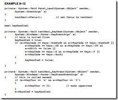
To accomplish filtering, use the KeyEventArg sˆ class argument e, which is passed to the KeyDown functon as illustrated in Example 8–12. In this example, C++ is used to accomplish the task of filtering the keyboard entry into the textbox control. The variable keyHandled is used to indicate whether or not the key is handled by the filtering. If keyHandled is set to false, the key has not been han- dled and it will appear in the textbox. Likewise, if keyhandled is set to true, the key has been handled and will not appear in the textbox. The condition of keyHandled is passed to Windows in the KeyPress event that also appears in Example 8–12. Note that Keys::D0 through Keys::D9 are the number keys on the QWERTY keyboard and Keys::NumPad0 through Keys::NumPad9 are on the numeric keypad. A D8 with the shift equal to false is the eight key and a D8 with shift equal to true is an asterisk key.

Programming the Microprocessor-0287

The if statement in KeyPress event tests the e->KeyCode value for the letters a, b, c d, e, and f, which can be either uppercase or lowercase. The KeyDown event tests for the numbers 0–9 on both the keyboard and the number pad. Also the backspace key is tested. If any of these are typed, keyHandled is set to false to indicate that these keys are not handled by the KeyDown function. The KeyPress event determines if the letter a–f is typed and converts it into uppercase by subtracting 32. The 32 is the bias between uppercase and lowercase letters in the ASCII code.

Next, a return with e->Handled set into true or false occurs. A return true causes Windows to dis- pose of the keystroke. In this case, if a number is typed, or the letters a through f or A through F, the keystroke is passed to Windows framework by the normal return false at the end of the KeyPress function. This filters the keystrokes so only A–F or 0–9 appears in the edit box.

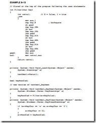
Example 8–12 is repeated using the inline assembler to accomplish the same task in Example 8–13. Here a function, called filter, returns a true or false that is passed to keyHandled in the KeyDown function. In this example, C++ seems to require less typing than assembly language, but it is important to be able to visualize both forms. Don’t forget to change the project property, Common Language Runtime Support to /CLR, so this will function correctly (see Chapter 7). Notice that KeyValue is used with the assembly version to pass a char to the Filter function. Also note that an integer return value of 0 is false and 1 is true.

Programming the Microprocessor-0288Programming the Microprocessor-0289

If this code is added to the application and executed, the only keys that will appear in the textbox control are 0–9 and A–F. Any amount of filtering can be done in a likewise manner in the Visual C++ Express environment. The properties of the textbox control include character casing, which could have been set to uppercase to shorten the filtering task, but here software accomplished the uppercase feature.

Using the Video Display

As with the keyboard, in Visual C++ objects are used to display information. The textbox control can be used to either read data or display data as can most objects. Modify the application pre- sented in Figure 8–1 so it contains an additional textbox control as shown in Figure 8–2. Notice that a few label controls have been added to the form to identify the contents of the textbox con- trols. In this new application the keyboard data is still read into textbox control textBox1, but when the Enter key is typed, a decimal version of the data entered into textBox1 appears in textBox2—the second textbox control. Make sure that the second control is named textBox2 to maintain compatibility with the software presented here.

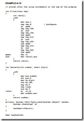
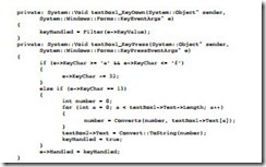
To cause the program to react to the Enter key, ASCII code 13 (0DH or 0x0d), modify the KeyPress function of Example 8–13 as shown in Example 8–14. Notice how the Enter key is detected using an else if. Once the Enter key is detected, the contents of textBox1 are converted to decimal for display in textBox2, as shown in Example 8–15.

Programming the Microprocessor-0290Programming the Microprocessor-0291

A slight problem arises with textbox data; the data entered into a textbox control is accessed as a string, but not as a hexadecimal number. In this example program (see Example 8–15), a function called Converts changes the hexadecimal character string into a number. The program now has two functions that contain assembly code.

Programming the Microprocessor-0292

Programming the Microprocessor-0293

Example 8–15 shows the completed application. When the Enter key is pressed, the pro- gram obtains the character string from textBox1 and converts it, a character at a time, into an integer using the Converts function. Once an integer is created, it is changed into a character string using the Convert class and its member function ToString for display in textBox2.

The assembly language in the Converts function converts from ASCII to binary by subtracting 30h from each digit. This action converts ASCII numbers (0–9) 30H through 39H to the binary numbers 0 through 9. It does not convert the letters 41H through 46H (A through F) to binary because the result is 11H through 16H and not 0AH through 0FH. To adjust the values obtained for the letters, use a cmp (compare) instruction to detect 11H through 16H and then subtract an additional 7 to convert from 11H through 16H to 0AH to 0FH. Once the ASCII digit is in binary form, the integer at number is shifted left four binary places and the binary version of the ASCII digit is ORed to it to accumulate the converted digits in temp1.

Once the hexadecimal number from textBox1 is converted to binary in variable number, it is displayed in textBox2 using the ToString function in the Convert class. As before, a return true informs the Windows interface that the Enter key has been processed by the program. If a return false is used in KeyPress for the Enter key, the computer generates an error beep.

Using a Timer in a Program

Timers are important in programming. A timer is programmed to fire or trigger after a known amount of time, which is given in milliseconds. The allowable range for the timer is from 1 to 2G milliseconds. This allows a timer to be programmed for just about any time needed. If programmed with 1000, the timer fires in 1 second, and if programmed with 60000, the timer fires in 1 minute and so forth. A timer may be used a single time or multiple times and as many timers as needed (up to 2 billion) may appear in a program. The timer is found in the toolbox at the Design window.

To illustrate the timer and its use in a program, a design appears in Figure 8–3 that allows a user to demonstrate a shift or a rotate on a binary number. The shift or rotate is animated with the timer in this program. The design contains two label controls and two button controls plus the timer control. Add all five of these controls to the application. The timer does not appear on the form, but in an area near the bottom of the design screen. Notice that a few properties of the form are changed so the icon is not shown and the Text property of the form is changed to Shift/Rotate instead of Form1. Also the Text properties of the labels and buttons are changed as indicated.

Programming the Microprocessor-0294

Once the form appears as shown in Figure 8–3, add event handler functions ( yellow light- ning bolt) for the two command buttons (Click) and for the timer (Tick). To add an event handler, click on the button or timer, go to the Properties window at the right of the screen, and click on the yellow lightning bolt and select the event. The program contains three handlers, two for but- ton clicks and one for a timer tick.

At the design screen go to the properties of the timer and set the interval to 500, which is 1⁄2 second. Do not enable the timer. The timer is enabled in the software when a button is clicked to either rotate a number or shift a number in 1⁄2-second animation steps.

Example 8–16 illustrates the software added to the application in the three handlers required to implement the application for Figure 8–3. The software for the two button click han- dlers is nearly identical except for the Boolean variable shift. The two statements in each place text onto the labels. If the shift button is pressed, “Shifted” is displayed, and if the rotate button is pressed, “Rotated” is displayed on label1. The second label has the test number 00011001 dis- played. The Boolean variable shift is set to true for the shift button and false for the rotate button. In both button handlers, count is set to 8 to shift or rotate the number 8 places. Finally, the last statement in each button handler starts the timer. As an alternative, the enabled member could be set to true to start the timer. Once the timer is started or enabled, it fires in 1⁄2 second and calls the Tick handler for timer1 where all the work is accomplished in this program.

The first statement in the timer tick function sets the digit string to zero. This is the number that shifts into the right end of label2. For a shift, it will remain a zero and for a rotate it depends on the leftmost digit of the number in label2. If shift is false (rotate) and the leftmost digit of label2 is 1, the digit is changed to 1. After the if statement, the number is shifted or rotated and placed on label2. If the count reaches 0, after 8 iterations in 4 seconds, the timer is disabled by setting the enabled member to false to stop the animation.

Programming the Microprocessor-0295Programming the Microprocessor-0296

This application is embellished by adding a pair of radio buttons to select right and left for the direction of the shift or rotate. Label2 can also be replaced with a textbox so the user could enter any binary number (with appropriate filtering) and shift or rotate it left or right.

The program does not use any assembly language, but if a breakpoint is inserted in the timer function, the assembly code can be viewed in Visual C++ Express. When the program Breaks, go to the Debug menu and select Windows. Next, select the Disassembly window to show the assembly language for the timer tick function.

The Mouse

The mouse pointing device, as well as a track ball, is accessed from within the framework of Visual C++ Express. Like many other devices under the control of Windows, the mouse can have message handlers installed in an application so that mouse movement and other functions can be used in a program. As we saw in prior examples, message handlers (event handlers) are installed in an application in the Properties section by clicking on the icon to the right of the lightning bolt. The mouse handlers are listed in Table 8–2.

For an illustration of how to use the mouse, refer to the example application presented in Figure 8–4. This example shows the mouse pointer coordinates as the pointer is moved within

Programming the Microprocessor-0297Programming the Microprocessor-0298

the dialog application. Although the software listing (see Example 8–17) does not use any assembly language, it does illustrate how to obtain and display the position of the mouse pointer. Notice how the MouseEventArgsˆ are used to obtain the location of the mouse pointer using the X and Y coordinates.

Programming the Microprocessor-0299

Example 8–17 illustrates the only part of the application that is modified to display the mouse coordinates. The MouseMove function is installed when the MouseMove event handler is installed in the program. This application uses two labels to display the mouse coordinates. These two objects are named label1 and label2 for the application. The MouseMove function returns the position of the mouse pointer in the Location data structure as members X and Y. This example uses the Convert class to convert the integer returned as the mouse point X or Y into an ASCII character string for placement on a label.

The mouse pointer does not track through the two labels in the application. In order to have the application display the coordinates in the labels as well as the form, two additional MouseMove handlers must be installed for the labels. Example 8–18 shows the addition of two more MouseMove functions and biases added to the X and Y coordinates so the mouse tracks through the labels. Where are the bias numbers obtained? The biases are in the Location proper- ties of each label where the label position is given as X, Y. The numbers in the application will depend on where the labels are placed on the form and could be obtained by using label1->Location.X and so forth.

Programming the Microprocessor-0300

Install a mouse handler for the Mouse Down event. Modify the application by adding the Mouse Down event handler as illustrated in Example 8–19. The function causes the left button to change the color of the labels to red when clicked and the right button changes the color of the labels to blue when pushed. The color codes used with most functions in Visual C++ are found in the Color class for most common colors. The application tests for the left and right mouse but- tons using the Button member of the Mouse Event Args object as shown. (Microsoft chose the name mouses for the Mouse Buttons enumerator.)

Programming the Microprocessor-0301


PROGRAMMING THE MICROPROCESSOR:MODULAR PROGRAMMING

PROGRAMMING THE MICROPROCESSOR

INTRODUCTION

This chapter develops programs and programming techniques using the inline assembler pro- gram from Visual C++ Express. The Visual C++ inline assembler has already been explained and demonstrated in prior chapters, but there are still more features to learn at this point.

Some programming techniques explained in this chapter include assembly language modules, keyboard and display manipulation, program modules, library files, using the mouse, using timers, and other important programming techniques. As an introduction to programming, this chapter provides a wealth of background on valuable programming techniques so that programs can be easily developed for the personal computer by using the inline assembler as a springboard for Visual C++ Express applications created for Windows.

CHAPTER OBJECTIVES

Upon completion of this chapter, you will be able to:

1. Use the MASM assembler and linker program to create programs that contain more than one module.

2. Explain the use of EXTRN and PUBLIC as they apply to modular programming.

3. Set up a library file that contains commonly used subroutines and learn how to use the DUMPBIN program.

4. Write and use MACRO and ENDM to develop macro sequences used with linear programming in modules that link to C++ code.

5. Show how both sequential and random access files are developed for use in a system.

6. Develop programs using event handlers to perform keyboard and display tasks.

7. Use conditional assembly language statements in programs.

8. Use the mouse in program examples.

MODULAR PROGRAMMING

Many programs are too large to be developed by one person. This means that programs are routinely developed by teams of programmers. The linker program is provided with Visual Studio so that programming modules can be linked together into a complete program. Linking is also available from the command prompt provided by Windows. This section of the text describes the linker, the linking task, library files, EXTRN, and PUBLIC as they apply to pro- gram modules and modular programming.

The Assembler and Linker

The assembler program converts a symbolic source module (file) into a hexadecimal object file. It is even a part of Visual Studio, located in the C: Program FilesMicrosoft Visual Studio .NET 2003Vc7 bin folder. We have seen many examples of symbolic source files, written in assembly language, in prior chapters. Example 8–1 shows how the assembler dialog that appears as a source module named NEW.ASM is assembled. Note that this dialog is used with version 6.15 at the DOS command line. The version that comes with Visual C will not work for 16-bit DOS programs. If a 16-bit assembler and linker are needed, they can be obtained in the Windows Driver Development Kit (DDK). Whenever you create a source file, it should have the extension of ASM, but as we learned in the last chapter, that is not always possible. Source files are created by using NotePad or almost any other word processor or editor capable of generating an ASCII file.

Programming the Microprocessor-0271

The assembler program (ML) requires the source file name following ML. In Example 8–1, the /Fl switch is used to create a listing file named NEW.LST. Although this is optional, it is rec- ommended so that the output of the assembler can be viewed for troubleshooting problems. The source listing file (.LST) contains the assembled version of the source file and its hexadecimal machine language equivalent. The cross-reference file (.CRF), which is not generated in this example, lists all labels and pertinent information required for cross-referencing. An object file is also generated by ML as an input to the linker program. In many cases we only need to generate an object file, which is accomplished by using the /c switch.

The linker program, which executes as the second part of ML, reads the object files that are created by the assembler program and links them together into a single execution file. An execution file is created with the file name extension EXE. Execution files are selected by typing the file name at the DOS prompt (C:). An example execution file is FROG.EXE, which is executed by typing FROG at the command prompt.

If a file is short enough (less than 64K bytes long), it can be converted from an execution file to a command file (.COM). The command file is slightly different from an execution file in that the program must be originated at location 0100H before it can execute. This means that the program must be no larger than 64K–100H in length. The ML program generates a command file if the tiny model is used with a starting address of 100H. Command files are only used with DOS or if a true binary version (for a EPROM/FLASH burner) is needed. The main advantage of a command file is that it loads off the disk into the computer much more quickly than an execution file. It also requires less disk storage space than the equivalent execution file.

Example 8–2 shows the linker program protocol when it is used to link the files NEW, WHAT, and DONUT. The linker also links library files (LIBS) so procedures, located with LIBS, can be used with the linked execution file. To invoke the linker, type LINK at the command prompt, as illustrated in Example 8–2. Note that before files are linked, they must first be assembled and they must be error-free. ML not only links the files, but it also assembles them prior to linking.

Programming the Microprocessor-0272

In this example, after typing ML, the linker program asks for the “Object Modules,” which are created by the assembler. In this example, we have three object modules: NEW, WHAT, and DONUT. If more than one object file exists, type the main program file first (NEW, in this example), followed by any other supporting modules.

Library files are entered after the file name and after the switch /LINK. In this example, library files were not entered. To use a library called NUMB.LIB while assembling a program called NEW.ASM, type ML NEW.ASM /LINK NUMB.LIB.

In the Windows environment you cannot link a program—you can only assemble a pro- gram. You must use Visual Studio to link the program files during the build. You can assemble a file or files and generate objects for use with Visual C++. Example 8–3 illustrates how a module is compiled, but not linked with ML. The /c switch (lowercase c) tells the assembler to compile and generate object files, /Cx preserves the case of all functions and variables, and /coff generates a common object file format output for the object files used in a 32-bit environment.

Programming the Microprocessor-0273

PUBLIC and EXTRN

The PUBLIC and EXTRN directives are very important to modular programming because they allow communications between modules. We use PUBLIC to declare that labels of code, data, or entire segments are available to other program modules. EXTRN (external) declares that labels are external to a module. Without these statements, modules could not be linked together to cre- ate a program by using modular programming techniques. They might link, but one module would not be able to communicate to another.

The PUBLIC directive is placed in the opcode field of an assembly language statement to define a label as public, so that the label can be used (seen by) by other modules. The label declared as public can be a jump address, a data address, or an entire segment. Example 8–4 shows the PUBLIC statement used to define some labels and make them public to other modules in a program fragment. When segments are made public, they are combined with other public segments that contain data with the same segment name.

The EXTRN statement appears in both data and code segments to define labels as external to the segment. If data are defined as external, their sizes must be defined as BYTE, WORD, or DWORD. If a jump or call address is external, it must be defined as NEAR or FAR. Example 8–5 shows how the external statement is used to indicate that several labels are external to the pro- gram listed. Notice in this example that any external address or data is defined with the letter E in the hexadecimal assembled listing. It is assumed that Example 8–4 and Example 8–5 are linked together.
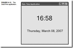
Programming the Microprocessor-0274Programming the Microprocessor-0275

Libraries

Library files are collections of procedures that are used by many different programs. These procedures are assembled and compiled into a library file by the LIB program that accompanies the MASM assembler program. Libraries allow common procedures to be collected into one place so they can be used by many different applications. You may have noticed when setting up Visual C++ to build the assembly language modules in Chapter 7 that many library files were in the link list used by Visual C++. The library file (FILENAME.LIB) is invoked when a program is linked with the linker program.

Why bother with library files? A library file is a good place to store a collection of related procedures. When the library file is linked with a program, only the procedures required by that program are removed from the library file and added to the program. If any amount of assembly language programming is to be accomplished efficiently, a good set of library files is essential and saves many hours in recoding common functions.

Creating a Library File. A library file is created with the LIB command, which executes the LIB.EXE program that is supplied with Visual Studio. A library file is a collection of assembled

.OBJ files that contains procedures or tasks written in assembly language or any other language. Example 8–6 shows two separate functions (UpperCase and LowerCase) included in a module that is written for Windows, which will be used to structure a library file. Please notice that the name of the procedure must be declared PUBLIC in a library file and does not necessarily need to match the file name, although it does in this example. A variable is transferred to each file, so the EXTRN statement also appears in each procedure to gain access to an external variable. Example 8–7 shows the C++ protocols that are required to use the functions in this library file in a C++ program, provided the library is linked to the program.

Programming the Microprocessor-0276

Programming the Microprocessor-0277

The LIB program begins with the copyright message from Microsoft, followed by the prompt Library name. The library name chosen is case for the CASE.LIB file. Because this is a new file, the library program must be prompted with the object file name. You must first assemble CASE.ASM with ML. The actual LIB command is listed in Example 8–8. Notice that the LIB program is invoked with the object name following it on the command line.

Programming the Microprocessor-0278

A utility program called DUMPBIN.EXE is provided to display the contents of the library or any other file. Example 8–9 shows the outcome of a binary dump using the /all switch to show the library module CASE.LIB and all its components. Near the top of this listing are the public names for _UpperCase and _LowerCase. The Raw Data #1 section contains the actual hexadecimal-coded instructions for the two procedures.

Programming the Microprocessor-0279

Programming the Microprocessor-0280Programming the Microprocessor-0281

Once the library file is linked to your program file, only the library procedures actually used by your program are placed in the execution file. Don’t forget to use the extern “C” statement in the C++ program to use a function from a library file.

In Visual C++ Express, a library is created by selecting the Class Library choice at the Create menu. This feature creates a DLL (dynamic link library) file that can be included in any C++ application. The DLL can contain C++ code or assembly code. To include the DLL in any program, under Project, select the “add reference” choice and browse to the DLL file. Once the DLL is added, place an #include at the start of the class where the DLL is to be used in a program.

Macros

A macro is a group of instructions that perform one task, just as a procedure performs one task. The difference is that a procedure is accessed via a CALL instruction, whereas a macro, and all the instructions defined in the macro, is inserted in the program at the point of usage. Creating a macro is very similar to creating a new opcode, which is actually a sequence of instructions, in this case, that can be used in the program. You type the name of the macro and any parameters associated with it, and the assembler then inserts them into the program. Macro sequences execute faster than procedures because there is no CALL or RET instruction to execute. The instructions of the macro are placed in your program by the assembler at the point where they are invoked. Be aware that macros will not function using the inline assembler; they only function in external assembly language modules.

The MACRO and ENDM directives delineate a macro sequence. The first statement of a macro is the MACRO instruction, which contains the name of the macro and any parameters associated with it. An example is MOVE MACRO A,B, which defines the macro name as MOVE. This new pseudo opcode uses two parameters: A and B. The last statement of a macro is the ENDM instruction, which is placed on a line by itself. Never place a label in front of the ENDM statement. If a label appears before ENDM, the macro will not assemble.

Example 8–10 shows how a macro is created and used in a program. The first six lines of code define the macro. This macro moves the word-sized contents of memory location B into word-sized memory location A. After the macro is defined in the example, it is used twice. The macro is expanded by the assembler in this example, so that you can see how it assembles to generate the moves. Any hexadecimal machine language statement followed by a number (1, in this example) is a macro expansion statement. The expansion statements are not typed in the source program; they are generated by the assembler (if .LISTALL is included in the program) to show that the assembler has inserted them into the program. Notice that the comment in the macro is preceded with ;; instead of ; as is customary. Macro sequences must always be defined before they are used in a program, so they generally appear at the top of the code segment.

Programming the Microprocessor-0282Programming the Microprocessor-0283

Example 8–11 shows a FILL macro that stores any number (parameter HOW_MANY) of 00H into the memory location addressed by parameter WHERE. Notice how the address FILL1 is treated when the macros are expanded. The assembler uses labels that start with ?? to designate them are assembler-generated labels.

The LOCAL directive must always be used on the line immediately following the MACRO statement or an error occurs. The LOCAL statement may have up to 35 labels, all separated with commas.

Placing MACRO Definitions in Their Own Module. Macro definitions can be placed in the program file as shown, or they can be placed in their own macro module. A file can be created that contains only macros to be included with other program files. We use the INCLUDE directive to indicate that a program file will include a module that contains external macro definitions. Although this is not a library file, for all practical purposes it functions as a library of macro sequences.

When macro sequences are placed in a file (often with the extension INC or MAC), they do not contain PUBLIC statements as does a library. If a file called MACRO.MAC contains macro sequences, the INCLUDE statement is placed in the program file as INCLUDE C:ASSMMACRO.MAC. Notice that the macro file is on drive C, subdirectory ASSM in this example. The INCLUDE statement includes these macros, just as if you had typed them into the file. No EXTRN statement is needed to access the macro statements that have been included. Programs may contain both macro include files and library files.