Simple PIC18 Projects:Two-Dice Project

PROJECT 6.3—Two-Dice Project

Project Description

This project is similar to Project 2, but here a pair of dice are used—as in many dice games such as backgammon—instead of a single dice.

The circuit shown in Figure 6.8 can be modified by adding another set of seven LEDs for the second dice. For example, the first set of LEDs can be driven from PORTC, the second set from PORTD, and the push-button switch can be connected to RB0 as before. Such a design requires fourteen output ports just for the LEDs. Later on we will see how the LEDs can be combined in order to reduce the input/output requirements. Figure 6.12 shows the block diagram of the project.

Project Hardware

The circuit diagram of the project is shown in Figure 6.13. The circuit is basically same as in Figure 6.8, with the addition of another set of LEDs connected to PORTD.

Simple PIC18 Projects-0020

The operation of the project is very similar to that for Project 2. Figure 6.14 shows the PDL for this project. At the beginning of the program the PORTC and PORTD pins are configured as outputs, and bit 0 of PORTB (RB0) is configured as input. The program then executes in a loop continuously and checks the state of the push-button switch. When the switch is pressed, two pseudorandom numbers between 1 and 6 are

Simple PIC18 Projects-0021

generated, and these numbers are sent to PORTC and PORTD. The LEDs remain at this state for 3 seconds, after which all the LEDs are turned OFF to indicate that the push-button switch can be pressed again for the next pair of numbers.

Project Program

The program is called LED4.C, and the program listing is given in Figure 6.15. At the beginning of the program Switch is defined as bit 0 of PORTB, and Pressed is defined as 0. The relationships between the dice numbers and the LEDs to be turned on are stored in an array called DICE, as in Project 2. Variable Pattern is the data sent to the LEDs. Program enters an endless for loop where the state of the push-button switch is checked continuously. When the switch is pressed, two random numbers are generated by calling function Number. The bit patterns to be sent to the LEDs are then determined and sent to PORTC and PORTD. The program then repeats inside the endless loop, checking the state of the push-button switch.


Simple PIC18 Projects:Chasing LEDs

PROJECT 6.1—Chasing LEDs

Project Description

In this project eight LEDs are connected to PORTC of a PIC18F452-type microcontroller, and the microcontroller is operated from a 4MHz resonator. When power is applied to the microcontroller (or when the microcontroller is reset), the LEDs turn ON alternately in an anticlockwise manner where only one LED is ON at any time. There is a one-second delay between outputs so the LEDs can be seen turning ON and OFF.

An LED can be connected to a microcontroller output port in two different modes: current sinking and current sourcing.

Current Sinking Mode

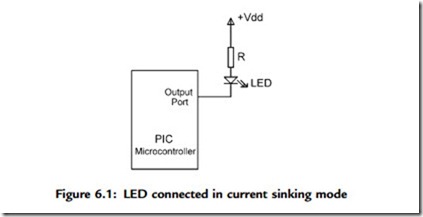
As shown in Figure 6.1, in current sinking mode the anode leg of the LED is connected to the þ5V supply, and the cathode leg is connected to the microcontroller output port through a current limiting resistor.

Simple PIC18 Projects-0005

The voltage drop across an LED varies between 1.4V and 2.5V, with a typical value of 2V. The brightness of the LED depends on the current through the LED, and this current can vary between 8 and 16mA, with a typical value of 10mA.

The LED is turned ON when the output of the microcontroller is at logic 0 so the current flows through the LED. Assuming the microcontroller output voltage is about 0.4V when the output is low, we can calculate the value of the required resistor as follows:

Simple PIC18 Projects-0006

Current Sourcing Mode

As shown in Figure 6.2, in current sourcing mode the anode leg of the LED is connected to the microcontroller output port and the cathode leg is connected to the ground through a current limiting resistor.

Simple PIC18 Projects-0007

In this mode the LED is turned ON when the microcontroller output port is at logic 1 (i.e., þ5V). In practice, the output voltage is about 4.85V and the value of the resistor can be determined as:

Simple PIC18 Projects-0008

Project Hardware

The circuit diagram of the project is shown in Figure 6.3. LEDs are connected to PORTC in current sourcing mode with eight 290-ohm resistors. A 4MHz resonator is connected between the OSC1 and OSC2 pins. Also, an external reset push button is connected to the MCLR input to reset the microcontroller when required.

Simple PIC18 Projects-0009

Project Program

The program is named as LED1.C, and the program listing is given in Figure 6.5. At the beginning of the program PORTC pins are configured as outputs by setting TRISC ¼ 0. Then an endless for loop is formed, and the LEDs are turned ON alternately in an anticlockwise manner to create a chasing effect. The program checks continuously so that when LED 7 is turned ON, the next LED to be turned ON is LED 0.

This program can be compiled using the mikroC compiler. Project settings should be configured to 4MHz clock, XT crystal mode, and WDT OFF. The HEX file (LED1.HEX) should be loaded to the PIC18F452 microcontroller using either an in-circuit debugger or a programming device.

Simple PIC18 Projects-0010

Further Development

The project can be modified such that the LEDs chase each other in both directions. For example, if the LEDs are moving in an anticlockwise direction, the direction can be changed so that when LED RB7 is ON the next LED to turn ON is RB6, when RB6 is ON the next is RB5, and so on.


Simple PIC18 Projects:Program Description Language (PDL)

Program Description Language (PDL)

Program description language (PDL) is free-format English-like text which describes the flow of control in a program. PDL is not a programming language but rather is

a tool which helps the programmer to think about the logic of the program before the program has been developed. Commonly used PDL keywords are described as follows.

START-END

Every PDL program description (or subprogram) should begin with a START keyword and terminate with an END keyword. The keywords in a PDL code should be highlighted in bold to make the code more clear. It is also a good practice to indent program statements between PDL keywords in order to enhance the readability of the code.

Simple PIC18 Projects-0002

Use IF, THEN, ELSE, and ENDIF keywords to describe the flow of control in a program.

Simple PIC18 Projects-0003

Simple PIC18 Projects-0004

Notice that the REPEAT-UNTIL loop is always executed at least once, and more than once if the condition at the end of the loop is not met.


C Programming Language:PIC Microcontroller Input-Output Port Programming

PIC Microcontroller Input-Output Port Programming

Depending on the type of microcontroller used, PIC microcontroller input-output ports are named as PORTA, PORTB, PORTC, and so on. Port pins can be in analog or digital mode. In analog mode, ports are input only and a built-in analog-to-digital converter and multiplexer circuits are used. In digital mode, a port pin can be configured as either input or output. The TRIS registers control the port directions, and there are TRIS registers for each port, named as TRISA, TRISB, TRISC, and so on. Clearing a TRIS register bit to 0 sets the corresponding port bit to output mode. Similarly, setting a TRIS register bit to 1 sets the corresponding port bit to input mode.

Ports can be accessed as a single 8-bit register, or individual bits of a port can be accessed. In the following example, PORTB is configured as an output port and all its bits are set to a 1:

C Programming Language-0161Similarly, the following example shows how the 4 upper bits of PORTC can be set as input and the 4 lower bits of PORTC can be set as output:

TRISC ¼ 0xF0;

Bits of an input-output port can be accessed by specifying the required bit number. In the following example, variable P2 is loaded with bit 2 of PORTB:

P2 ¼ PORTB.2;

All the bits of a port can be complemented by the statement:

PORTB ¼ rvPORTB;


C Programming Language

There are several C compilers on the market for the PIC18 series of microcontrollers. These compilers have many similar features, and they can all be used to develop C- based high-level programs for PIC18 microcontrollers.

Some of the C compilers used most often in commercial, industrial, and educational PIC18 microcontroller applications are:

• mikroC

• PICC18

• C18

• CCS

The popular and powerful mikroC, developed by MikroElektronika (web site: www.microe.com), is easy to learn and comes with rich resources, such as a large number of library functions and an integrated development environment with a built-in simulator and an in-circuit debugger (e.g., mikroICD). A demo version of the compiler with a 2K program limit is available from MikroElektronika.

PICC18, another popular C compiler, was developed by Hi-Tech Software (web site: www.htsoft.com) and is available in two versions: standard and professional.

A powerful simulator and an integrated development environment (Hi-Tide) are provided by the company. PICC18 is supported by the PROTEUS simulator (www.labcenter.co.uk) which can be used to simulate PIC microcontroller–based systems. A limited-period demo version of this compiler is available on the developer’s web site.

C18 is a product of Microchip Inc. (web site: www.microchip.com). A limited-period demo version, as well as a limited functionality version of C18 with no time limit, are available from the Microchip web site. C18 includes a simulator and supports hardware and software development tools such as in-circuit emulators (e.g., ICE2000) and in-circuit debuggers (e.g., ICD2).

CCS has been developed by the Custom Computer Systems Inc. (web site: www. ccsinfo.com). The company offers a limited-period demo version of their compiler. CCS provides a large number of built-in functions and supports an in-circuit debugger (e.g., ICD-U40) which are very helpful in the development of PIC18 microcontroller– based systems.

In this book we are mainly concentrating on the use of the mikroC compiler, and most of the projects are based on this compiler.


Microcomputer Systems:BCD Numbers

BCD Numbers

BCD (binary coded decimal) numbers are usually used in display systems such as LCDs and 7-segment displays to show numeric values. In BCD, each digit is a 4-bit number from 0 to 9. As an example, Table 1.4 shows the BCD numbers between 0 and 20.

Microcomputer Systems-0039

Microcomputer Systems-0040

Microcomputer Systems-0041

Summary

Chapter 1 has provided an introduction to the microprocessor and microcontroller systems. The basic building blocks of microcontrollers were described briefly. The chapter also provided an introduction to various number systems, and described how to convert a given number from one base into another.

The important topics of floating point numbers and floating point arithmetic were also described with examples.


PIC18F Microcontroller Series

PIC16-series microcontrollers have been around for many years. Although these are excellent general purpose microcontrollers, they have certain limitations. For example, the program and data memory capacities are limited, the stack is small, and the interrupt structure is primitive, all interrupt sources sharing the same interrupt vector. PIC16- series microcontrollers also do not provide direct support for advanced peripheral interfaces such as USB, CAN bus, etc., and interfacing with such devices is not easy. The instruction set for these microcontrollers is also limited. For example, there are no multiplication or division instructions, and branching is rather simple, being a combination of skip and goto instructions.

Microchip Inc. has developed the PIC18 series of microcontrollers for use in high-pin- count, high-density, and complex applications. The PIC18F microcontrollers offer cost- efficient solutions for general purpose applications written in C that use a real-time operating system (RTOS) and require a complex communication protocol stack such as TCP/IP, CAN, USB, or ZigBee. PIC18F devices provide flash program memory in sizes from 8 to 128Kbytes and data memory from 256 to 4Kbytes, operating at a range of to 5.0 volts, at speeds from DC to 40MHz.

The basic features of PIC18F-series microcontrollers are:

• 77 instructions

• PIC16 source code compatible

• Program memory addressing up to 2Mbytes

• Data memory addressing up to 4Kbytes

• DC to 40MHz operation

• 8 x 8 hardware multiplier

• Interrupt priority levels

• 16-bit-wide instructions, 8-bit-wide data path

• Up to two 8-bit timers/counters

• Up to three 16-bit timers/counters

• Up to four external interrupts

• High current (25mA) sink/source capability

• Up to five capture/compare/PWM modules

• Master synchronous serial port module (SPI and I2C modes)

• Up to two USART modules

• Parallel slave port (PSP)

• Fast 10-bit analog-to-digital converter

• Programmable low-voltage detection (LVD) module

• Power-on reset (POR), power-up timer (PWRT), and oscillator start-up timer (OST)

• Watchdog timer (WDT) with on-chip RC oscillator

• In-circuit programming

In addition, some microcontrollers in the PIC18F family offer the following special features:

• Direct CAN 2.0 bus interface

• Direct USB 2.0 bus interface

• Direct LCD control interface

• TCP/IP interface

• ZigBee interface

• Direct motor control interface

Most devices in the PIC18F family are source compatible with each other. Table 2.1 gives the characteristics of some of the popular devices in this family. This chapter offers a detailed study of the PIC18FXX2 microcontrollers. The architectures of most of the other microcontrollers in the PIC18F family are similar.

The reader may be familiar with the programming and applications of the PIC16F series. Before going into the details of the PIC18F series, it is worthwhile to compare the features of the PIC18F series with those of the PIC16F series.

The following are similarities between PIC16F and PIC18F:

• Similar packages and pinouts

• Similar special function register (SFR) names and functions

• Similar peripheral devices

PIC18F Microcontroller Series-0042

• Subset of PIC18F instruction set

• Similar development tools

The following are new with the PIC18F series:

• Number of instructions doubled

• 16-bit instruction word

• Hardware 8 x 8 multiplier

• More external interrupts

• Priority-based interrupts

• Enhanced status register

• Increased program and data memory size

• Bigger stack

• Phase-locked loop (PLL) clock generator

• Enhanced input-output port architecture

• Set of configuration registers

• Higher speed of operation

• Lower power operation


Microcomputer Systems:Addition and Subtraction of Floating Point Numbers

Addition and Subtraction of Floating Point Numbers

The exponents of floating point numbers must be the same before they can be added or subtracted. The steps to add or subtract floating point numbers are:

• Shift the smaller number to the right until the exponents of both numbers are the same. Increment the exponent of the smaller number after each shift.

• Add (or subtract) the mantissa of each number as an integer calculation, without considering the decimal points.

• Normalize the result. An example follows. Example 1.37

Show decimal numbers 0.510 and 0.7510 in floating point and then calculate the sum of these numbers.

Microcomputer Systems-0037

Microcomputer Systems-0038

This floating point number is equal to decimal number 1.25, which is the sum of decimal numbers 0.5 and 0.75.

A program for converting floating point numbers into decimal, and decimal numbers into floating point, is available for free on the following web site:

http://babbage.cs.qc.edu/courses/cs341/IEEE-754.html


Microcomputer Systems:Floating Point Numbers and Converting a Floating Point Number into Decimal

Floating Point Numbers

Floating point numbers are used to represent noninteger fractional numbers, for example, 3.256, 2.1, 0.0036, and so forth. Floating point numbers are used in most engineering and technical calculations. The most common floating point standard is the IEEE standard, according to which floating point numbers are represented with 32 bits (single precision) or 64 bits (double precision).

In this section we are looking at the format of 32-bit floating point numbers only and seeing how mathematical operations can be performed with such numbers.

According to the IEEE standard, 32-bit floating point numbers are represented as:

Microcomputer Systems-0028

The most significant bit indicates the sign of the number, where 0 indicates the number is positive, and 1 indicates it is negative.

The 8-bit exponent shows the power of the number. To make the calculations easy, the sign of the exponent is not shown; instead, the excess-128 numbering system is used. Thus, to find the real exponent we have to subtract 127 from the given exponent. For example, if the mantissa is “10000000,” the real value of the mantissa is 128 – 127 ¼ 1.

The mantissa is 23 bits wide and represents the increasing negative powers of 2. For example, if we assume that the mantissa is “1110000000000000000000,” the value of this mantissa is calculated as 2-1 þ 2-2 þ 2-3 ¼ 7/8.

The decimal equivalent of a floating point number can be calculated using the formula:

Microcomputer Systems-0029

The smallest number in 32-bit floating point format is:

Microcomputer Systems-0030

Converting a Floating Point Number into Decimal

To convert a given floating point number into decimal, we have to find the mantissa and the exponent of the number and then convert into decimal as just shown.

Some examples are given here.

Microcomputer Systems-0031