An introduction to schedulers:Co-operative and pre-emptive scheduling

Co-operative and pre-emptive scheduling

We have discussed in very general terms the use of a scheduler to execute functions at particular times. Before we begin to consider the creation and use of a scheduler in detail in the next chapter, we need to appreciate that there are two broad classes of scheduler:

● The co-operative scheduler

● The pre-emptive scheduler

The features of the two types of scheduler are compared in Figures 13.5 and 13.6.

The co-operative scheduler

● A co-operative scheduler provides a single-tasking system architecture

Operation:

● Tasks are scheduled to run at specific times (either on a periodic or one-shot basis)

● When a task is scheduled to run it is added to the waiting list

● When the CPU is free, the next waiting task (if any) is executed

● The task runs to completion, then returns control to the scheduler

Implementation:

● The scheduler is simple and can be implemented in a small amount of code

● The scheduler must allocate memory for only a single task at a time

● The scheduler will generally be written entirely in a high-level language (such as ‘C’)

● The scheduler is not a separate application; it becomes part of the developer’s code

Performance:

● Obtaining rapid responses to external events requires care at the design stage

Reliability and safety:

● Co-operate scheduling is simple, predictable, reliable and safe

An introduction to schedulers-0234

An introduction to schedulers-0236

The pre-emptive scheduler

● A pre-emptive scheduler provides a multitasking system architecture

Operation:

● Tasks are scheduled to run at specific times (either on a periodic or one-shot basis)

● When a task is scheduled to run it is added to the waiting list

● Waiting tasks (if any) are run for a fixed period then, if not completed, are paused and placed back in the waiting list. The next waiting task is then run for a fixed period, and so on

Implementation:

● The scheduler is comparatively complicated, not least because features such as semaphores must be implemented to avoid conflicts when ‘concurrent’ tasks attempt to access shared resources

● The scheduler must allocate memory to hold all the intermediate states of pre-empted tasks

● The scheduler will generally be written (at least in part) in Assembly language

● The scheduler is generally created as a separate application

Performance:

● Rapid responses to external events can be obtained

Reliability and safety:

● Generally considered to be less predictable, and less reliable, than co-operative approaches

An introduction to schedulers-0237

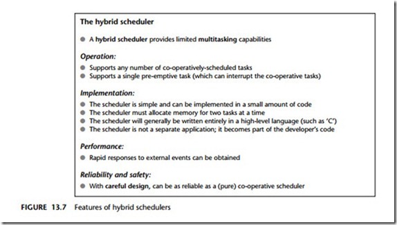
In this book, we use mainly co-operative schedulers and will make limited use of hybrid schedulers (Figure 13.7). Together, these two forms of scheduler will provide the facilities we require (the ability to share a timer between multiple tasks, the ability to run both ‘periodic’ and ‘one-shot’ tasks): they do this while avoiding the complexi- ties inherent in (fully) pre-emptive environments.

The key reason why the co-operative schedulers are both reliable and predictable is that only one task is active at any point in time: this task runs to completion, and then returns control to the scheduler. Contrast this with the situation in a fully pre- emptive system with more than one active task. Suppose one task in such a system which is reading from a port and the scheduler performs a ‘context switch’, causing a different task to access the same port: under these circumstances, unless we take action to prevent it, data may be lost or corrupted.

This problem arises frequently in multitasking environments where we have what are known as ‘critical sections’ of code. Such critical section are code areas that – once started – must be allowed to run to completion without interruption. Examples of critical sections include:

● Code which modifies or reads variables, particularly global variables used for inter- task communication. In general, this is the most common form of critical section, since inter-task communication is often a key requirement.

clip_image005

The hybrid scheduler

● A hybrid scheduler provides limited multitasking capabilities

Operation:

● Supports any number of co-operatively-scheduled tasks

● Supports a single pre-emptive task (which can interrupt the co-operative tasks)

Implementation:

● The scheduler is simple and can be implemented in a small amount of code

● The scheduler must allocate memory for two tasks at a time

● The scheduler will generally be written entirely in a high-level language (such as ‘C’)

● The scheduler is not a separate application; it becomes part of the developer’s code

Performance:

● Rapid responses to external events can be obtained

Reliability and safety:

● With careful design, can be as reliable as a (pure) co-operative scheduler

An introduction to schedulers-0238

● Code which interfaces to hardware, such as ports, analog-to-digital converters (ADCs) and so on. What happens, for example, if the same ADC is used simultane- ously by more than one task?

● Code which calls common functions. What happens, for example, if the same function is called simultaneously by more than one task?

In a co-operative system, these problems do not arise, since only one task is ever active at the same time. To deal with such critical sections of code in a pre-emptive system, we have two main possibilities:

● ‘Pause’ the scheduling by disabling the scheduler interrupt before beginning the critical section; re-enable the scheduler interrupt when we leave the critical section.

● Or use a ‘lock’ (or some other form of ‘semaphore mechanism’) to achieve a similar result.

The first solution is that, when we start accessing the shared resource (say Port X), we disable the scheduler. This solves the immediate problem since (say) Task A will be allowed to run without interruption until it has finished with Port X. However, this ‘solution’ is less than perfect. For one thing, by disabling the scheduler, we will no longer be keeping track of the elapsed time and all timing functions will begin to drift

– in this case by a period up to the duration of Task A every time we access Port X. This simply is not acceptable.

The use of locks is a better solution and appears, at first inspection, easy to imple- ment. Before entering the critical section of code, we ‘lock’ the associated resource;

when we have finished with the resource we ‘unlock’ it. While locked, no other process may enter the critical section.1

This is one way we might try to achieve this:

1 Task A checks the ‘lock’ for Port X it wishes to access.

2 If the section is locked, Task A waits.

3 When the port is unlocked, Task A sets the lock and then uses the port.

4 When Task A has finished with the port, it leaves the critical section and unlocks the port.

Implementing this algorithm in code also seems straightforward, as illustrated in Listing 13.7.

An introduction to schedulers-0239

1. Of course, this is only a partial solution to the problems caused by multitasking. If the purpose of Task A is to read from an ADC, and Task B has locked the ADC when the Task A is involved, then Task A cannot carry out its required activity. Use of locks, or any other mechanisms, will not solve this problem; however, they may prevent the system from crashing. Of course, by using a co- operative scheduler, these problems do not arise.

Consider the part of the code labelled ‘A’ in Listing 13.7. If our system is fully pre- emptive, then our task can reach this point at the same time as the scheduler performs a context switch and allows (say) Task B access to the CPU. If Task Y also wants to access the Port X

We can then have a situation as follows:

● Task A has checked the lock for Port X and found that the port is not locked; Task A has, however, not yet changed the lock flag.

● Task B is then ‘switched in’. Task B checks the lock flag and it is still clear. Task B sets the lock flag and begins to use Port X.

● Task A is ‘switched in’ again. As far as Task A is concerned, the port is not locked; this task therefore sets the flag and starts to use the port, unaware that Task B is already doing so.

● …

As we can see, this simple lock code violates the principal of mutual exclusion: that is, it allows more than one task to access a critical code section. The problem arises because it is possible for the context switch to occur after a task has checked the lock flag but before the task changes the lock flag. In other words, the lock ‘check and set code’ (designed to control access to a critical section of code), is itself a critical section.

This problem can be solved. For example, because it takes little time to ‘check and set’ the lock code, we can disable interrupts for this period. However, this is not in itself a complete solution: because there is a chance that an interrupt may have occurred even in the short period of ‘check and set’, we may then need to check the relevant interrupt flag(s) and, if necessary, call the relevant ISR(s). This can be done, but it adds to the complexity of the operating environment.
 

An introduction to schedulers:A closer look at pre-emptive schedulers

A closer look at pre-emptive schedulers

The discussion in this section is more technical than the previous sections in this chapter and may be omitted on a first reading of the book.

Various research studies have demonstrated that, compared to pre-emptive schedulers, co-operative schedulers have a number of desirable features. For example, Nissanke (1997, p. 237) notes:

[Pre-emptive] schedules carry greater runtime overheads because of the need for context switching – storage and retrieval of partially computed results. [Co-operative] algorithms do not incur such overheads. Other advantages of [co-operative] algorithms include their better under- standability, greater predictability, ease of testing and their inherent capability for guaranteeing exclusive access to any shared resource or data.

Similarly, Allworth (1981, pp. 53–4) notes:

Significant advantages are obtained when using this [co-operative] technique. Since the processes are not interruptable, poor synchronisation does not give rise to the problem of shared data. Shared subroutines can be implemented without producing re-entrant code or implementing lock and unlock mechanisms.

Also, in a recent presentation, Bates (2000) identified the following four advantages of co-operative scheduling, compared to pre-emptive alternatives:

1 The scheduler is simpler

2 The overheads are reduced

3 Testing is easier

4 Certification authorities tend to support this form of scheduling

Despite these observations, all the authors cited and the vast majority of other workers in this area focus on the use of pre-emptive schedulers. At least part of the reason why pre-emptive approaches are more widely discussed is because of confu- sion over the options available. For example, Bennett (1994, p. 205) states:

If we consider the scheduling of time allocation on a single CPU there are two basic alternatives: [1] cyclic, [2] pre-emptive.

In fact, contrary to Bennett’s assertion, what he refers to as cyclic scheduling is essentially a form of SUPER LOOP [page 162]. As we saw in Chapter 9, this type of architecture is suitable only for use in a restricted range of very simple applications, in particular those where accurate timing is not a key requirement and limited memory and CPU resources are available: SUPER LOOP is not representative of the broad range of co-operative scheduling architectures that are available.

Bennett is, however, not alone: other researchers make similar assumptions (see Barnett, 1995). For example, Locke (1992, p. 37) – in a widely cited publication – suggests that:

Traditionally, there have been two basic approaches to the overall design of application systems exhibiting hard real-time deadlines: the cyclic executive … and the fixed priority [pre- emptive] architecture.

Similarly, Cooling (1991, pp. 292–3) compares co-operative and pre-emptive schedul- ing approaches. Again, however, his discussion of co-operative schedulers is restricted to a consideration of the special case of cyclic scheduling: as a result, his conclusion that a pre-emptive approach is more effective is unsurprising.

Where the different characteristics of pre-emptive and co-operative scheduling are compared equitably, the main concern expressed is often that long tasks will have an impact on the responsiveness of a co-operative scheduler. This concern is succinctly summarized by Allworth (1981):

[The] main drawback with this [co-operative] approach is that while the current process is run- ning, the system is not responsive to changes in the environment. Therefore, system processes must be extremely brief if the real-time response [of the] system is not to be impaired.

There are four main technical reasons why such concerns are, generally, misplaced:

● In many embedded applications, the task duration is extremely brief. For example, consider one of the more complex algorithms considered in this book: proportional integral differential (PID) control. Even the most basic 8051 microcontroller can carry out a PID calculation in around 0.4 ms (see p. 872): even in flight control – where PID algorithms remain in widespread use – sample rates of around 10 ms are common, and a 0.4 ms calculation does not impose a significant processor load.

● Where the system does have long tasks, this is often because the developer is unaware of some simple techniques that can be used to break down these tasks in an appropriate way and – in effect – convert ‘long tasks called infrequently’ into ‘short tasks called frequently’. Such techniques are used throughout this book; they are introduced and explained in Chapter 16.

● In many cases, the increased power of microcontrollers has more than kept up with performance demands in many embedded systems. For example, the PID per- formance figures just given assumed an original 8051 microcontroller, with a 1 MIPS performance level. As we saw in Chapter 3, numerous low-cost members of this family now have performance levels between 5 and 50 MIPS. Often a simple, cost-effective, way of addressing performance concerns is not to use a more com- plex software architecture, but, instead, to update the hardware.

● If upgrades to the task design or microcontroller do not provide sufficient perform- ance improvements, then more than one microcontroller can be used. This is now very common. For example, a typical automotive environment containing more than 40 embedded processors (Leen et al., 1999). With the increased availability of such processing elements, long tasks may be readily ‘migrated’ to another proces- sor, leaving the main CPU free to respond rapidly, if necessary, to other events. (See Part F of this book for numerous examples of this process.)

Finally, it should be noted that the reasons why pre-emptive schedulers have been more widely discussed and used may not be for technical reasons at all: in fact, the use of pre-emptive environments can be seen to have clear commercial advantages for some companies. For example, a co-operative scheduler may be easily constructed, entirely in a high-level programming language, in around 300 lines of ‘C’ code, as we demonstrate in Chapter 9. The code is highly portable, easy to understand and to use and is, in effect, freely available. By contrast, the increased complexity of a pre- emptive operating environment results in a much larger code framework (some ten times the size, even in a simple implementation: Labrosse, 1998). The size and com- plexity of this code makes it unsuitable for ‘in-house’ construction in most situations and therefore provides the basis for a commercial ‘RTOS’ products to be sold, gener- ally at high prices and often with expensive run-time royalties to be paid. The continued promotion and sale of such environments has, in turn, prompted further academic interest in this area. For example, according to Liu and Ha, (1995):

[An] objective of reengineering is the adoption of commercial off-the-shelf and standard operat- ing systems. Because they do not support cyclic scheduling, the adoption of these operating systems makes it necessary for us to abandon this traditional approach to scheduling.

Conclusions

In this chapter, we have explained what a scheduler is and outlined the differences between co-operative and pre-emptive scheduling. We have argued that a co-operative scheduler provides a simple and reliable operating environment that matches pre- cisely the needs of most embedded applications.

Over recent years we have used versions of the co-operative schedulers presented in this book in numerous ‘real’ applications. We have also helped many student groups use this architecture in their first embedded systems. We have no doubt that the cor- rect use of these schedulers not only results in simple, transparent and reliable designs, but also make it easier for ‘desktop’ developers to adapt rapidly to the chal- lenges of embedded system development.


Co-operative schedulers

Introduction

In this chapter, we discuss techniques for creating co-operative schedulers suitable for use in single-processor environments. These provide a very flexible and predictable software platform for a wide range of embedded applications, from the simplest con- sumer gadget up to and including aircraft control systems.

The following pattern is presented in this chapter:

CO OPERA TIVE SCHEDULER [page 255]

A co-operative scheduler provides a simple, highly predictable environment. The scheduler is written entirely in ‘C’ and becomes part of the application: this tends to make the operation of the whole system more transparent and eases development, maintenance and porting to different environments. Memory overheads are seven bytes per task and CPU requirements (which vary with tick interval) are low.


An introduction to schedulers:What is a scheduler?

What is a scheduler?

There are two ways of viewing a scheduler:

● At one level, a scheduler can be viewed as a simple operating system that allows tasks to be called periodically or (less commonly) on a one-shot basis.

● At a lower level, a scheduler can be viewed as a single timer interrupt service routine that is shared between many different tasks. As a result, only one timer needs to be initialized, and any changes to the timing generally requires only one function to be altered. Furthermore, we can generally use the same scheduler whether we need to execute one, ten or 100 different tasks. Note that this ‘shared ISR’ is very similar to the shared printing facilities (for example) provided by a desktop OS.

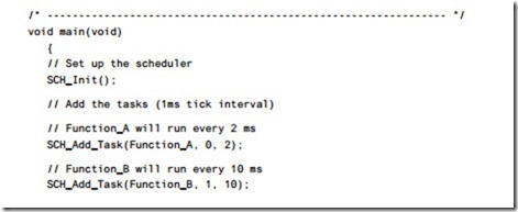
For example, Listing 13.6 shows how we might schedule the three tasks shown in Listing 13.5, this time using a scheduler.

An introduction to schedulers-0233


An introduction to schedulers:Executing multiple tasks at different time intervals

Executing multiple tasks at different time intervals

While the great majority of embedded systems are required to run only one pro- gram, they do need to run multiple tasks (implemented as ‘C’ functions in this book): these tasks must, as mentioned earlier, run on a periodic or one-shot basis. These tasks will typically have different durations and will run at different time intervals. For example, we might need to read the input from an ADC every millisec- ond, read one or more switches every 200 milliseconds and update an LCD display every 3 milliseconds.

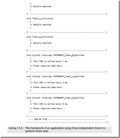
We can try to run more than one task by extending the technique discussed in Section 13.5. For example, suppose that we have a microcontroller device with (say) three timers available and wanted to use these timers to control the execution of three tasks, by using a separate interrupt service routine to perform each task (Listing 13.5).

An introduction to schedulers-0232

Provided we have sufficient timers available, this approach will generally work. However, it would breach some basic software design guidelines.

For example, in Listing 13.5, we have three different timers to manage and – if we had 100 tasks – we would require 100 timers. This would make system maintenance very difficult; for example, 100 changes would be required if we changed the oscilla- tor frequency. It would also be difficult to extend; for example, how can we add another task if there are no further hardware timers available?

In addition to contravening one of the most basic software design guidelines, there is a more specific problem with Listing 13.5. This arises in situations where more than one interrupt occurs simultaneously. As we saw in Chapter 1, having more than one active interrupt in a system can result in unpredictable – and hence, unreliable – pat- terns of behaviour.

Looking back at Listing 13.5 we can see that there will inevitably be occasions when more than one interrupt is generated at the same time. Dealing with this situation is not impossible, but it would add greatly to the complexity of the application.

Overall, as we will see in the next section, use of a scheduler provides a much cleaner solution.


Example: Flashing an LED

Example: Flashing an LED

The example just given is rather abstract. Here we present another example of a timer-driven interrupt service routine. In this case, we use the timer to flash an LED on and off at regular time intervals (Listing 13.4).

Note that in this application we are using Timer 1 overflows to invoke the ISR. As we discussed in Chapter 11, Timer 1 does not have a 16-bit ‘auto reload’ mode; as a consequence, the timer must be manually reloaded every time it overflows: the function Timer_1_Manual_Reload() carries out this operation.

An introduction to schedulers-0229

An introduction to schedulers-0230


An introduction to schedulers-0231


An introduction to schedulers:A better solution

A better solution

A better solution to the problems outlined is to use timer-based interrupts as a means of invoking functions at particular times.

Timer-based interrupts and interrupt service routines

As we saw in Chapter 1, an interrupt is a hardware mechanism used to notify a proces- sor that an ‘event’ has taken place: such events may be internal events or external events. Altogether the core 8051 / 8052 architecture supports seven interrupt sources:

● Three timer/counter interrupts (related to Timer 0, Timer 1 and – where available – Timer 2)

● Two UART-related interrupts (note: these share the same interrupt vector, and can be viewed as a single interrupt source)

● Two external interrupts

In addition, there is one addition interrupt source over which the programmer has minimal control:

● The ‘power-on reset’ (POR) interrupt

When an interrupt is generated, the processor ‘jumps’ to an address at the bottom of the CODE memory area. These locations must contain suitable code with which the microcontroller can respond to the interrupt or, more commonly, the locations will include another ‘jump’ instruction, giving the address of suitable ‘interrupt serv- ice routine’ located elsewhere in (CODE) memory.

While the process of handling interrupts may seem rather complicated, creating interrupt service routines (ISRs) in a high-level language is a straightforward process, as illustrated in Listing 13.3.

An introduction to schedulers-0224

The result of running the program shown in Listing 13.3 in the Keil hardware simula- tor is shown in Figure 13.3.

An introduction to schedulers-0225

Much of Listing 13.3 should be familiar. The code to set up Timer 2 in the function Timer_2_Init() is the same as the delay code discussed in Chapter 11, the two main differences being that, in this case:

1 The timer will generate an interrupt when it overflows

2 The timer will be automatically reloaded, and will immediately begin counting again We discuss both of these differences in the following subsections.

The interrupt service routine (ISR)

The interrupt generated by the overflow of Timer 2, invokes the ISR called, here, X().

An introduction to schedulers-0226

The link between this function and the timer overflow is made using the Keil key- word interrupt (included after the function header in the function definition):

void X(void) interrupt INTERRUPT_Timer_2_Overflow

plus the following #define directive:

#define INTERRUPT_Timer_2_Overflow 5

To understand where the ‘5’ comes from, note that the interrupt numbers used in ISRs directly correspond to the enable bit index of the interrupt source in the 8051 IE SFR. That is, bit 0 of the IE register will be linked to a function using ‘interrupt 0’. Table 13.1 shows the link between the interrupt sources and the required interrupt numbers for the original 8051/8052.

Overall, the use of interrupts linked to timer overflows is a safe and powerful tech- nique which will be applied throughout this book.

Automatic timer reloads

As noted earlier, when Timer 2 overflows, it is automatically reloaded and immedi- ately begins counting again. In this case, the timer is reloaded using the contents of the ‘capture’ registers (note that the names of these registers vary slightly between chip manufacturers):

An introduction to schedulers-0227An introduction to schedulers-0228

This automatic reload facility ensures that the timer keeps generating the required ticks, at precisely 1 ms intervals, without any software load, and without any inter- vention from the user’s program.

The ability to ‘automatically reload’ Timer 2 simplifies the use of this timer as a source of regular ticks. Note that Timer 0 and Timer 1 also have an auto-reload capability, but only when operating as an 8-bit timer. In most applications, an 8- bit timer can only be used to generate interrupts at intervals of around 0.25 ms (or less); this is not generally useful.


An introduction to schedulers:Assessing the Super Loop architecture

Assessing the Super Loop architecture

Many of the features of the modern desktop OS, such as graphics capability, printing and disk access, are of little value in embedded applications, where sophisticated graphics screens, printers and disks are unavailable.

As a result, as we saw in Chapter 9, the software architecture used in many simple embedded applications is a form of SUPER LOOP (Listing 13.1).

An introduction to schedulers-0220

Listing 13.1 Part of a simple Super Loop demonstration

The main advantages of the Super Loop architecture illustrated in Listing 13.1 are (1) that it is simple, and therefore easy to understand, and (2) that it consumes virtually no system memory or CPU resources.

However, we get ‘nothing for nothing’: Super Loops consume little memory or processor resources because they provide few facilities to the developer. A particular limitation with this architecture is that it is very difficult to execute Task X at precise intervals of time: as we will see, this is a very significant drawback.

For example, consider a collection of requirements assembled from a range of dif- ferent embedded projects (in no particular order):

● The current speed of the vehicle must be measured at 0.5 second intervals.

● The display must be refreshed 40 times every second.

● The calculated new throttle setting must be applied every 0.5 seconds.

● A time-frequency transform must be performed 20 times every second.

● If the alarm sounds, it must be switched off (for legal reasons) after 20 minutes.

● If the front door is opened, the alarm must sound in 30 seconds if the correct password is not entered in this time.

● The engine vibration data must be sampled 1,000 times per second.

● The frequency-domain data must be classified 20 times every second.

● The keypad must be scanned every 200 ms.

● The master (control) node must communicate with all other nodes (sensor nodes and sounder nodes) once per second.

● The new throttle setting must be calculated every 0.5 seconds.

● The sensors must be sampled once per second.

We can summarize this list by saying that many embedded systems must carry out tasks at particular instants of time. More specifically, we have two kinds of activ- ity to perform:

Periodic tasks, to be performed (say) once every 100 ms

One-shot tasks, to be performed once after a delay of (say) 50 ms

This is very difficult to achieve with the primitive architecture shown in Listing

13.1. Suppose, for example, that we need to start Task X every 200 ms, and that the task takes 10 ms to complete. Listing 13.2 illustrates one way in which we might adapt the code in Listing 13.1 in order to try to achieve this.

An introduction to schedulers-0222

The approach illustrated in Listing 13.2 is not generally adequate, because it will only work if the following conditions are satisfied:

1 We know the precise duration of Task X

2 This duration never varies

In practical applications, determining the precise task duration is rarely straightfor- ward. Suppose we have a very simple task that does not interact with the outside world but, instead, performs some internal calculations. Even under these rather restricted circumstances, changes to compiler optimization settings – even changes to an apparently unrelated part of the program – can alter the speed at which the task executes. This can make fine-tuning the timing very tedious and error prone.

The second condition is even more problematic. Often in an embedded system the task will be required to interact with the outside world in a complex way. In these cir- cumstances the task duration will vary according to outside activities in a manner over which the programmer has very little control.


An introduction to schedulers:The desktop OS

The desktop OS

As stated in the preface, it is assumed in this book that readers will have had previous experience of software development for desktop computer systems. As we discussed in Chapter 1, the desktop / workstation environment plays host to many information sys- tems, as well as general-purpose desktop applications, such as word processors. A common characteristic of modern desktop environments is that the user interacts with the application through a high-resolution graphics screen, plus a keyboard and a mouse. Support for this complex user interface is provided by the operating system and its associated libraries.

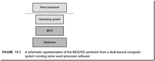
In such an environment, the program the user requires (such as a word processor) is usually loaded from disk on demand, along with any required data (such as a word processor file). Figure 13.1 shows a typical operating environment for such a word processor. Here the application is well insulated from the underlying hardware. For example, when the user wished to save her latest novel on disk, the word processor del- egates most of the necessary work to the operating system, which in turn may delegate many of the hardware-specific commands to the BIOS (basic input/output system).

The desktop PC does not require an operating system (or BIOS). However, for most users, the main advantage of a personal computer is its flexibility: that is, that the same piece of equipment has the potential to run many thousands of different programs. If the PC had no operating system, each of these programs would need to be able to carry out all the low-level functions for itself. This would be very inefficient and would tend to make applications more expensive. It would also be likely to lead to errors, as many functions would have to be duplicated in even the smallest of programs.

We can get a feel for the type of problems that would result in a world without Windows (or UNIX) if we consider ‘DOS’, an early operating system widely used on PCs. Readers old enough to have used DOS applications will remember that every program needed to provide a suitable printer driver: if the printer was subsequently changed, this generally meant that every application on the PC needed to be upgraded in order to take advantage of the new hardware. With Windows, this problem does not arise: when a new printer is purchased, a single driver is required. When this had been installed, every program on the computer can immediately make use of the new hardware.

One way of viewing this is that a desktop operating system is used to run multiple programs, and the operating systems provides the ‘common code’ (for printing, file storage, graphics, and so forth) that is required by this set of programs: this reduces the need to duplicate identical program components, reducing the opportunity for errors and making the overall system more reliable and easier to maintain.

An introduction to schedulers-0218An introduction to schedulers-0219


QUESTIONS AND PROBLEMS ON THE PENTIUM II, PENTIUM III, PENTIUM 4, AND CORE2 MICROPROCESSORS.

QUESTIONS AND PROBLEMS

1. What is the size of the level 1 cache in the Pentium II microprocessor?

2. What sizes are available for the level 2 cache in the Pentium II microprocessor? (List all versions.)

3. What is the difference between the level 2 cache on the Pentium-based system and the Pentium II-based system?

4. What is the difference between the level 2 cache in the Pentium Pro and the Pentium II?

5. The speed of the Pentium II Xeon level 2 cache is times faster than the cache in the Pentium II (excluding the Celeron).

6. How much memory can be addressed by the Pentium II?

7. Is the Pentium II available in integrated circuit form?

8. How many pin connections are found on the Pentium II cartridge?

9. What is the purpose of the PICD control signals?

10. What happened to the read and write pins on the Pentium II?

11. At what bus speeds does the Pentium II operate?

12. How fast is the SDRAM connected to the Pentium II system for a 100 MHz bus speed version?

13. How wide is the Pentium II memory if ECC is employed?

14. What new model-specific registers (MSR) have been added to the Pentium II microprocessor?

15. What new CPUID identification information has been added to the Pentium II micro- processor?

16. How is a model-specific register addressed and what instruction is used to read it?

17. Write software that stores 12H into model-specific register 175H.

18. Write a short procedure that determines whether the microprocessor contains the SYSEN- TER and SYSEXIT instructions. Your procedure must return carry set if the instructions are present, and return carry cleared if not present.

19. How is the return address transferred to the system when using the SYSENTER instruction?

20. How is the return address retrieved when using the SYSEXIT instruction to return to the application?

21. The SYSENTER instruction transfers control to software at what privilege level?

22. The SYSEXIT instruction transfers control to software at what privilege level?

23. What is the difference between the FSAVE and the FXSAVE instructions?

24. The Pentium III is an extension of the architecture.

25. What new instructions appear in the Pentium III microprocessor that do not appear in the Pentium Pro microprocessor?

26. What changes to the power supply does the Pentium 4 or Core2 microprocessor require?

27. Write a short program that reads and displays the serial number of the Pentium III micro- processor on the video screen.

28. Develop a short C++ function that returns a bool value of true if the Pentium 4 supports hyper-threaded technology and false if it does not support it.

29. Develop a short C++ function that returns a bool value of true if the Pentium 4 or Core2 sup- port SSE, SSE2, and SSE3 extensions.

30. Compare, in your own words, hyper-threading to dual processing. Postulate on the possibility of including additional processors beyond four.

31. What is a Core2 processor?