Designing embedded systems using patterns

In this second introductory chapter, we consider why ‘traditional’ software design techniques provide only limited support for the developers of embedded applications and argue that software patterns can provide a useful adjunct to such techniques.

Introduction

Most branches of engineering have a long history. Work in the area of control systems, for example, might be said to have begun with the seminal studies by James Watt on the flywheel governor in the 1760s, while work in electrical engineering can be dated back to the work of Michael Faraday, who is generally credited with the invention of the elec- tric motor in 1821. It can be argued that the practice of civil engineering has the longest history of all, originating, perhaps, with the building of the Egyptian pyramids, or to Greek or Roman times: certainly the Institution of Civil Engineers was founded in England (UK) in 1818 and is the oldest professional engineering institution in the world.

For the software engineer, a different situation applies. The first mass-produced minicomputer, the PDP-8, was launched only in 1965 and the first microprocessor only in 1971. As a result of the comparatively late introduction, and subsequent rapid evolution, of small programmable computer systems, the field of software engineering has had little opportunity to mature. In the limited time available, much work on soft- ware engineering has focused on the design process and, in particular, on the development and use of various graphical notations, including process-oriented notations, such as dataflow diagrams (Yourdon, 1989: see Figure 2.1), and object-oriented notations, such as the ‘Unified Modelling Language’ (Fowler and Scott, 2000). The use of such notations is supported by ‘methodologies’: these are collections of ‘recipes’ for

SNAG-0065

[Note: that in this example, and throughout most of this book, we have used a process-oriented (dataflow) notation1 to record the design solutions: this remains the most popular approach for embedded applications, in part because process-oriented languages (notably ‘C’) are popular in this area. Although object-oriented languages (like C++) are comparatively uncommon in microcontroller- based embedded projects at the present time, object-oriented design notations could equally well be used to record the design pre- sented here.]

1. Please refer to Appendix A for details of this notation.

software design, detailing how and when particular notations should be used in a proj- ect (see, for example, Pont, 1996). The designs that result from the application of these techniques consist of a set of linked diagrams, each following a standard notation, and accompanied by appropriate supporting documentation (Yourdon, 1989; Booch, 1994; Pont, 1996; Fowler and Scott, 2000).

As the title suggests, we are concerned in this book with the development of soft-

ware for embedded systems. In the past, despite the ubiquitous nature of embedded applications, the design of such systems has not been a major focus of attention with- in the software field. Indeed, in almost all cases, software design techniques have been developed first to meet the needs of the developers of desktop business systems (DeMarco, 1978; Rumbaugh et al., 1991; Coleman et al., 1994), and then subsequent- ly ‘adapted’ in an attempt to meet the needs of developers of real-time and / or embed- ded applications (Hatley and Pirbhai, 1987; Selic et al., 1994; Awad et al., 1996; Douglass, 1998). We will argue (in Section 2.2) that the resulting software design tech- niques, although not without merit, cannot presently meet the needs of the designers of embedded systems. We then go on to propose (Sections 2.2 and 2.4) that the use of software patterns as an adjunct to existing techniques represents a promising way to alleviate some of the current problems.


Designing embedded systems using patterns:Patterns

Patterns

We can sum up the conclusions from these two examples by saying that – for those developers with experience of control system design, or the use of LED displays – the tasks are straightforward: however, for those without such experience, even the small- est of decisions can have unexpected repercussions. Unfortunately, the standard design notations that have been developed do not provide any means of substituting for the lack of experience on the part of a particular designer. The consequence is not difficult to predict, and is summarized succinctly in this quotation from an experienced devel- oper of embedded applications: ‘It’s ludicrous the way we software people reinvent the wheel with every project’ (Ganssle, 1992).

To address these problems use of ‘objects’, ‘agents’ or any new form of software building block or design notation will not greatly help. Instead, what is needed is a means of what we might call ‘recycling design experience’: specifically, we would like to find a way of incorporating techniques for reusing successful design solutions into the design process.

Recently, many developers have found that software patterns offer a way of achiev- ing this. Current work on software patterns has been inspired by the work of Christopher Alexander and his colleagues (for example Alexander et al., 1977; Alexander, 1979). Alexander is an architect who first described what he called ‘a pat- tern language’ relating various architectural problems (in buildings) to good design solutions. He defines patterns as ‘a three-part rule, which expresses a relation between a certain context, a problem, and a solution’ (Alexander, 1979, p.247).

For example, consider Alexander’s WINDOW PLACE pattern, summarized briefly in Figure 2.8. This takes the form of a recognizable problem, linked to a corresponding solution. More specifically, like all good patterns, WINDOW PLACE does the following:

● It describes, clearly and concisely, a successful solution to a significant and well- defined problem.

● It describes the circumstances in which it is appropriate to apply this solution.

● It provides a rationale for this solution.

● It describes the consequences of applying the solution.

● It gives the solution a name.

This basic concept of descriptive problem–solution mappings was adopted by Ward Cunningham and Kent Beck who used some of Alexander’s techniques as the basis for a small ‘pattern language’ intended to provide guidance to novice Smalltalk program- mers (Cunningham and Beck, 1987). This work was subsequently built upon by Erich Gamma and colleagues who, in 1995, published an influential book on general- purpose object-oriented software patterns (Gamma et al., 1995).

For example, consider the OBSER VER pattern (Gamma et al., 1995), illustrated in Figure 2.9. This describes how to link the components in a multi-component applica- tion, so that when the state of one part of the system is altered, all other related parts are notified and, if necessary, updated. This pattern successfully solves the problem, while leaving the various system components loosely coupled, so that they may be more easily altered or reused in subsequent projects.

Designing embedded systems-0070

As described by Gamma et al., a subject may have any number of observers, all of which are noti- fied when the state of the subject changes: in response, observers will (usually) synchronize their state with the subject’s state, illustrated schematically as:

Designing embedded systems-0071

One of the situations is which OBSER VER may be applied is when a change to one component requires changing others, and you do not know how many other components need to be altered.

One important consequence of using this pattern is that the various communicating components are loosely coupled together: this means, for example, that new components can be added, or existing components can be removed, with little impact on the rest of the program.


Time-triggered systems

Time-triggered systems

The main alternative to event-triggered systems architectures are time-triggered architectures (see, for example, Kopetz, 1997). As with event-triggered architectures, time-triggered approaches are used in both desktop systems and in embedded systems.

To understand the difference between the two approaches, consider that a hospital doctor must look after the needs of ten seriously ill patients overnight, with the support of some nursing staff. The doctor might consider two ways of performing this task:

● The doctor might arrange for one of the nursing staff to waken her, if there is a significant problem with one of the patients. This is the ‘event-triggered’ solution.

● The doctor might set her alarm clock to ring every hour. When the alarm goes off, she will get up and visit each of the patients, in turn, to check that they are well and, if necessary, prescribe treatment. This is the ‘time-triggered’ solution.

For most doctors, the event-triggered approach will seem the more attractive, because they are likely to get a few hours of sleep during the course of the night. By contrast, with the time-triggered approach, the doctor will inevitably suffer sleep deprivation.

However, in the case of many embedded systems – which do not need sleep – the time-triggered approach has many advantages. Indeed, within industrial sectors where safety is an obvious concern, such as the aerospace industry and, increasingly, the automotive industry, time-triggered techniques are widely used because it is accepted, both by the system developers and their certification authorities, that they help improve reliability and safety (see, for example, Allworth, 1981; MISRA, 1994; Storey, 1996; Nissanke, 1997; Bates, 2000 for discussion of these issues).

The main reason that time-triggered approaches are preferred in safety-related appli- cations is that they result in systems which have very predictable behaviour. If we revis- it the hospital analogy, we can begin to see why this is so.

Suppose, for example, that our ‘event-triggered’ doctor is sleeping peacefully. An apparently minor problem develops with one of the patients and the nursing staff decide not to awaken the doctor but to deal with the problem themselves. After another two hours, when four patients have ‘minor’ problems, the nurses decide that they will have to wake the doctor after all. As soon as the doctor sees the patients, she recognizes that two of them have a severe complications, and she has to begin surgery. Before she can complete the surgery on the first patient, the second patient is very close to death.

Consider the same example with the ‘time-triggered’ doctor. In this case, because the patient visits take place at hourly intervals, the doctor sees each patient before seri- ous complications arise and arranges appropriate treatment. Another way of viewing this is that the workload is spread out evenly throughout the night. As a result, all the patients survive the night without difficulty.

In embedded applications, the (rather macabre) hospital situation is mirrored in the event-driven application by the occurrence of several events (that is, several interrupts) at the same time. This might indicate, for example, that two different faults had been detected simultaneously in an aircraft or simply that two switches had been pressed at the same time on a keypad.

To see why the simultaneous occurrence of two interrupts causes a problem, con- sider what happens in the 8051 architecture in these circumstances. Like many micro- controllers, the original 8051 architecture supports two different interrupt priority lev- els: low and high. If two interrupts (we will call them Interrupt 1 and Interrupt 2) occur in rapid succession, the system will behave as follows:

● If Interrupt 1 is a low-priority interrupt and Interrupt 2 is a high-priority interrupt: The interrupt service routine (ISR) invoked by a low-priority interrupt can be interrupted by a high-priority interrupt. In this case, the low-priority ISR will be paused, to allow the high-priority ISR to be executed, after which the operation of the low-priority ISR will be

completed. In most cases, the system will operate correctly (provided that the two ISRs do not interfere with one another).

● If Interrupt 1 is a low-priority interrupt and Interrupt 2 is also a low-priority interrupt:

The ISR invoked by a low-priority interrupt cannot be interrupted by another low- priority interrupt. As a result, the response to the second interrupt will be at the very least delayed; under some circumstances it will be ignored altogether.

● If Interrupt 1 is a high-priority interrupt and Interrupt 2 is a low-priority interrupt:

The interrupt service routine (ISR) invoked by a high-priority interrupt cannot be interrupted by a low-priority interrupt. As a result, the response to the second interrupt will be at the very least delayed; under some circumstances it will be ignored altogether.

● If Interrupt 1 is a high-priority interrupt and Interrupt 2 is also a high-priority interrupt:

The interrupt service routine (ISR) invoked by a high-priority interrupt cannot be inter- rupted by another high-priority interrupt. As a result, the response to the second interrupt will be at the very least delayed; under some circumstances it will be ignored altogether.

Note carefully what this means! There is a common misconception among the devel- opers of embedded applications that interrupt events will never be lost. This simply is not true. If you have multiple sources of interrupts that may appear at ‘random’ time intervals, interrupt responses can be missed: indeed, where there are several active interrupt sources, it is practically impossible to create code that will deal cor- rectly with all possible combinations of interrupts.

It is the need to deal with the simultaneous occurrence of more than one event that both adds to the system complexity and reduces the ability to predict the behaviour of an event-triggered system under all circumstances. By contrast, in a time-triggered embedded application, the designer is able to ensure that only single events must be handled at a time, in a carefully controlled sequence.

As already mentioned, the predictable nature of time-triggered applications makes this approach the usual choice in safety-related applications, where reliability is a cru- cial design requirement. However, the need for reliability is not restricted to systems such as fly-by-wire aircraft and drive-by-wire passenger cars: even at the lowest level, an alarm clock that fails to sound on time or a video recorder that operates intermit- tently, or a data monitoring system that – once a year – loses a few bytes of data may not have safety implications but, equally, will not have high sales figures.

In addition to increasing reliability, the use of time-triggered techniques can help to reduce both CPU loads and memory usage: as a result, as we demonstrate throughout this book, even the smallest of embedded applications can benefit from the use of this form of system architecture.


Event-triggered systems

Event-triggered systems

Many applications are now described as ‘event triggered’ or ‘event driven’. For example, in the case of modern desktop applications, the various running applications must respond to events such as mouse clicks or mouse movements. A key expectation of users is that such events will invoke an ‘immediate’ response.

In embedded systems, event-triggered behaviour is often achieved through the use of interrupts (see following box). To support these, event-triggered system architectures often provide multiple interrupt service routines.

SNAG-0064

In Figure 1.5 the system executes two (background) tasks, Task 1 and Task 2. During the execution of Task 1, an interrupt is raised, and an ‘interrupt service routine’ (ISR1) deals with this event. During the execution of Task 2, another interrupt is raised, this time dealt with by ISR2.

Note that, from the perspective of the programmer, an ISR is simply a function that is ‘called by the microcontroller’, as a result of a particular hardware event.


What is a time-triggered embedded system?:Real-time systems

Real-time systems

Users of most software systems like to have their applications respond quickly: the difference is that in most information systems and general desktop applications, a rapid response is a useful feature, while in many real-time systems it is an essential feature.

Consider, for example, the greatly simplified aircraft autopilot application illustrated schematically in Figure 1.4.

Here, we assume that the pilot has entered the required course heading and that the system must make regular and frequent changes to the rudder, elevator, aileron and engine settings (for example) in order to keep the aircraft following this path.

An important characteristic of this system is the need to process inputs and generate outputs very rapidly, on a time scale measured in milliseconds. In this case, even a slight delay in making changes to the rudder setting (for example) may cause the plane to oscillate very unpleasantly or, in extreme circumstances, even to crash. As a consequence of the need for rapid processing, few software engineers would argue with a claim that the autopilot system is representative of a broad class of real-time systems.

In order to be able to justify the use of the aircraft system in practice, it is not

SNAG-0063

enough simply to ensure that the processing is ‘as fast as we can make it’: in this situ- ation, as in many other real-time applications, the key characteristic is deterministic processing. What this means is that in many real-time systems we need to be able to guarantee that a particular activity will always be completed within (say) 2 ms, or at precisely 6 ms intervals: if the processing does not match this specification, then the application is not simply slower than we would like, it is useless.

Tom De Marco has provided a graphic description of this form of hard real-time requirement in practice, quoting the words of a manager on a software project:

‘We build systems that reside in a small telemetry computer, equipped with all kinds of sensors to measure electromagnetic fields and changes in temperature, sound and physical disturbance. We analyze these signals and transmit the results back to a remote computer over a wide-band chan- nel. Our computer is at one end of a one-meter long bar and at the other end is a nuclear device. We drop them together down a big hole in the ground and when the device detonates, our computer collects data on the leading edge of the blast. The first two-and-a-quarter milliseconds after detonation are the most interesting. Of course, long before millisecond three, things have gone down hill badly for our little computer. We think of that as a real-time constraint.

(De Marco, writing in the foreword to Hatley and Pirbhai, 1987) In this case, it is clear that this real-time system must complete its recording on time: it has no opportunity for a ‘second try’. This is an extreme example of what is sometimes referred to as a ‘hard’ real-time system.

Note that, unlike this military example, many applications (like the aircraft system outlined earlier), involve repeated sampling of data from the real world (via a trans- ducer and analog-to-digital converter) and, after some (digital) processing, creating an appropriate analog output signal (via a digital-to-analog converter and an actuator). Assuming that we sample the inputs at 1000 Hz then, to qualify as a real-time system, we must be able to process this input and generate the corresponding output, before we are due to take the next sample (0.001 seconds later).

To summarize, consider the following ‘dictionary’ definition of a real-time system:

‘[A] program that responds to events in the world as they happen. For example, an automatic-pilot program in an aircraft must respond instantly in order to correct deviations from its course. Process control, robotics, games, and many military applications are examples of real-time systems.’

(Hutchinson New Century Encyclopedia (CD ROM edition, 1996))

It is important to emphasize that a desire for rapid processing, either on the part of the designer or on the part of the client for whom the system is being developed, is not enough, on its own, to justify the description ‘real time’. This is often misunder- stood, even by developers within the software industry. For example, Waites and Knott have stated:

‘Some business information systems also require real-time control … Typical examples include airline booking and some stock control systems where rapid turnover is the norm.’(Waites and Knott, 1996, p.194)

In fact, neither of these systems can sensibly be described as a real-time application.


What is a time-triggered embedded system?:Desktop systems

Desktop systems

The desktop / workstation environment plays host to many information systems, as well as general-purpose desktop applications, such as word processors. A common characteristic of modern desktop environments is that the user interacts with the application through a high-resolution graphics screen, plus a keyboard and a mouse (Figure 1.3).

In addition to this sophisticated user interface, the key distinguishing characteristics of the desktop system is the associated operating system, which may range from DOS through to a version of Windows or the UNIX operating system.

As we will see, the developer of embedded applications rarely has an operating sys- tem, screen, keyboard or mouse available.

SNAG-0062


What is a time-triggered embedded system?

In this introductory chapter, we consider what is meant by the phrases ‘embedded system’ and ‘time-triggered system’ and we examine how these important areas overlap.

Introduction

Current software applications are often given one of a bewildering range of labels:

● Information system

● Desktop application

● Real-time system

● Embedded system

● Event-triggered system

● Time-triggered system

There is considerable overlap between the various areas. We will therefore briefly con- sider all six types of application in this chapter, to put our discussions of time-triggered embedded systems in the remainder of this book in context.

Information systems

Information systems (ISs), and particularly ‘business information systems’, represent a huge number of applications. Although many of the challenges of information system development are rather different from those we will be concerned with in this book, a

basic understanding of such systems is useful, not least because most of the existing techniques for real-time and embedded development have been adapted from those originally developed to support the IS field.

As an example of a basic information system, consider the payroll application illustrated schematically in Figure 1.1.

This application will, we assume, be used to print the pay slips for a company, using employee data provided by the user and stored in the system. The printing of the cheques might take several hours: if a particularly complex set of calculations are required at the end of a tax year, and the printing is consequently delayed by a few minutes, then this is likely to be, at most, inconvenient. We will contrast this ‘incon- venience’ with the potentially devastating impact of delays in a real-time application in later examples.

ISs are widely associated with storage and manipulation of large amounts of data stored in disk files. Implementations in file-friendly languages, such as COBOL, were common in the 1960s and 1970s and such systems remain in widespread use, although most such systems are now in a ‘maintenance’ phase and new implementations in such languages are rare.

Modern IS implementations make far greater use of relational databases, accessed and manipulated using the SQL language. Relational database technology is well proven, safe and built on a formal mathematical foundation. While the design and implementation of large, reliable, relational database systems is by no means a trivial activity, the range of skills required to develop applications for use in a home or small business is limited. As a consequence, the implementation of such small relational

Refer to Appendix A for details of this notation

database systems has ceased to be a specialized process and relational database design tools are now available to, and used by, many desktop computer users as part of stan- dard ‘office’ packages.

However, new demands are being placed on the designers of information systems. Many hospitals, for example, wish to store waveforms (for example, ECGs or auditory evoked responses) or images (for example, X-rays or magnetic resonance images) and other complex data from medical tests, alongside conventional text records. An exam- ple of an ECG trace is shown in Figure 1.2.

For the storage of waveforms, images or speech relational databases systems, opti- mized for handling a limited range of data types (such as strings, characters, integers and real numbers), are not ideal. This has increased interest in object-oriented database systems (’object databases’), which are generally considered to be more flexible.

SNAG-0061


Learning to think co-operatively:Hardware timeout

Hardware timeout

Context

● You are developing an embedded application using one or more members of the 8051 family of microcontrollers.

● The application has a time-triggered architecture, constructed using a scheduler.

Problem

How do you produce well-defined timeout behaviour so that, for example, you can respond within exactly 0.5 ms if an expected event does not occur?

Background

See LOOP TIMEOUT [page 298] for relevant background material.

Solution
As we saw in HARDW ARE DELA Y [page 194], we can create portable and easy to use delay code for the 8051 family as follows:

Learning to think co-operatively-0289

HARDW ARE TIMEOUT involves a simple variation on this technique and allows precise timeout delays to be easily generated.

For example, in LOOP TIMEOUT [page 298] we considered the process of reading from an ADC in a Philips 8XC552 microcontroller.

This was the original, potentially dangerous, code:

Learning to think co-operatively-0290Learning to think co-operatively-0291Learning to think co-operatively-0292

Hardware resource implications

HARDW ARE TIMEOUT requires the use of a timer.

Reliability and safety implications

HARDW ARE TIMEOUT is the most reliable form of timeout structure we consider in the book.

Portability
Like all timer-based patterns, this code may be easily ported to other members of the 8051 family. It may also be ported to other microcontrollers.

Overall strengths and weaknesses

ccurate timeout delays may be obtained using HARDW ARE TIMEOUT .

The number of timers available is very limited: however, when using a co- operative scheduler, the tasks are running co-operatively and the same timer may be used in several tasks at the same time.

Related patterns and alternative solutions

See LOOP TIMEOUT [page 298] for an alternative that does not require the use of any timer hardware.

In addition, HARDW ARE W A TCHDOG [page 217] provides an alternative; however, it is rather crude by comparison and detects errors at the application (rather than task) level.

Example: Testing hardware timeouts

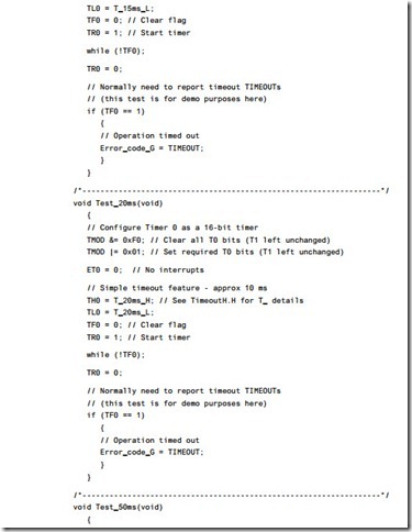
Listing 15.4 illustrates the delays obtained with some hardware timeouts using the Keil hardware simulator (see also Figure 15.3).

Learning to think co-operatively-0295Learning to think co-operatively-0296Learning to think co-operatively-0297Learning to think co-operatively-0298Learning to think co-operatively-0299Learning to think co-operatively-0300


Learning to think co-operatively:Loop timeout

Loop timeout

Context
● You are developing an embedded application using one or more members of the 8051 family of microcontrollers.

● The application has a time-triggered architecture, constructed using a scheduler.

Problem

How do you ensure that your system will not ‘hang’ while waiting for a hardware operation (such as an AD conversion or serial data transfer) to complete?

Background

The Philips 8XC552 is an Extended 8051 device with a number of on-chip peripherals, including an 8-channel, 10-bit ADC. Philips provide an application note (AN93017) that describes how to use this microcontroller. This application note includes the following code:

// Wait until AD conversion finishes (checking ADCI) while ((ADCON & ADCI) == 0);

Such code is potentially unreliable, because there are circumstances under which our application may ‘hang’. This might occur for one or more of the following reasons:

● If the ADC has been incorrectly initialized, we cannot be sure that a data conver- sion will be carried out.

● If the ADC has been subjected to an excessive input voltage, then it may not operate at all.

● If the variables ADCON or ADCI were not correctly initialized, they may not oper- ate as required.

Such problems are not, of course, unique to this particular microcontroller or even to ADCs. Such code is common in embedded applications.

If your application is to be reliable, you need to be able to guarantee that no func- tion will hang in this way. Loop timeouts offer a simple but effective means of providing such a guarantee.

Solution

A loop timeout may be easily created. The basis of the code structure is a software delay, created as follows:

unsigned integer Timeout_loop = 0;

while (++Timeout_loop);

This loop will keep running until the variable Timeout_loop reaches its maxi- mum value (assuming 16-bit integers) of 65,535 and then overflows. When this happens, the program will continue. Note that, without some simulation studies or prototyping, we cannot easily determine how long this delay will be. However, we do know that the loop will, eventually, time out.

Such a loop is not terribly useful. However, if we consider again the ADC example given in ‘Background’, we can easily extend this idea. Recall that the original code was as follows:

// Wait until AD conversion finishes (checking ADCI) while ((ADCON & ADCI) == 0);

Here is a modified version of this code, this time incorporating a loop timeout:

tWord Timeout_loop = 0;

// Take sample from ADC

// Wait until conversion finishes (checking ADCI)

// – simple loop timeout

while (((ADCON & ADCI) == 0) && (++Timeout_loop != 0));

Note that this alternative implementation is also useful:

tWord Timeout_loop = 1;

// Take sample from ADC

// Wait until conversion finishes (checking ADCI)

// – simple loop timeout

while (((ADCON & ADCI) == 0) && (Timeout_loop != 0))

{

Timeout_loop++; // Disable for use in hardware simulator…

}

The advantage of this second technique is that the loop timeout may be easily commented out, if required, when executing the code on a hardware simulator.

In both cases, we now know that the loop cannot go on ‘for ever’.

Note that we can vary the duration of the loop timeout by changing the initial value loaded into loop variable. The file TimeoutL.H, reproduced in Listing 15.1 and included on the CD in the directory associated with this chapter, includes a set of constants that give, very approximately, the specified timeout values.

We give an example of how to use this file in the following sections.

Hardware resource implications

LOOP TIMEOUT does not use a timer and imposes an almost negligible CPU and memory load.

Reliability and safety implications

Using a L OOP T IMEOUT can result in a huge reliability and safety improvement at minimal cost. However, if practical, HARDW ARE TIMEOUT [page 305] is usually an even better solution.

Portability

Loop timeouts will work in any environment. However, the timings obtained will vary dramatically between microcontrollers and compilers.

Overall strengths and weaknesses

clip_image005clip_image006Much better than executing code without any form of timeout protection. Many applications use a timer for RS232 baud rate generation, and another

timer to run the scheduler. In many 8051 devices, this leaves no further

timers available to implement a HARDW ARE TIMEOUT [page 305]. In these circumstances, use of a loop is the only practical way of implementing effective timeout behaviour.

clip_image007Timings are difficult to calculate and timer values are not portable. HARDW ARE TIMEOUT is always a better solution, if you have a spare timer available.

Related patterns and alternative solutions

As mentioned under ‘Reliability and safety implications’, HARDW ARE TIMEOUT [page 305] is often a better alternative to LOOP TIMEOUT .

In addition, HARDW ARE W A TCHDOG [page 217] provides an alternative; however, it is rather crude by comparison and detects errors at the application (rather than task) level.

Example: Test program for loop timeout code

As noted, loop timeouts must be carefully hand-tuned to give accurate delay values.

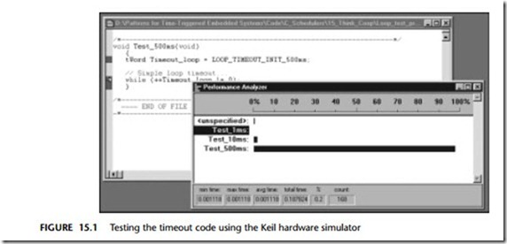
The program in Listing 15.2 can be used to test such timeout code.

The program is run in the Keil hardware simulator to check the timings (Figure 15.1).

Remember: Changes in compiler optimization settings – and even apparently unconnected changes to the rest of the program – can change these timings, because they alter the way in which the compiler makes use of the available memory areas.

For a final test in the pre-production code, set a port pin high at start of the time- out and clear it at the end. Use an oscilloscope to measure the resulting delay.

Learning to think co-operatively-0286

Example: Loop timeouts in an I2C library

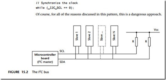
We discuss the I2C bus in detail in Chapter 23. Very briefly, I2C is a two-wire serial bus. The two wires are referred to as the serial data (SDA) and serial clock (SCL) lines (Figure 15.2). When the bus is free, both SCL and SDA lines are HIGH.

Here we consider how loop timeouts are used in a version of the I2C library.

At certain stages in the data transmission, we need to ‘synchronize the clocks’. This means waiting for the ‘clock’ line to be pulled high (by a slave device). Some I2C code libraries include fragments of code similar to the following to achieve this:

// Synchronize the clock while (_I2C_SCL == 0);

Of course, for all of the reasons discussed in this pattern, this is a dangerous approach.

Learning to think co-operatively-0287

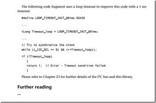
The following code fragment uses a loop timeout to improve this code with a 1 ms timeout:

Learning to think co-operatively-0288


Learning to think co-operatively

Introduction

Using a co-operative scheduler in your application has a number of benefits, one of which being that the development process is simplified. However, to get the maxi- mum benefit from the scheduler you need to learn to think ‘co-operatively’.

For example, one key difference between scheduled and desktop applications is the need to think carefully about issues of timing and task duration. More specifically, as we saw in Chapter 14, a key requirement in applications using a co-operative sched- uler is that – for all tasks, under all circumstances – the task duration, DurationTask,

must satisfy the following condition:

DurationTask < Tick Interval

The patterns in this chapter are intended to help you meet this condition by ensur- ing that tasks will abort if they cannot complete within a specified period of time. Specifically, two timeout patterns are presented here:

LOOP TIMEOUT [page 298]

HARDW ARE TIMEOUT [page 305]