An introduction to shared-clock schedulers:Why additional processors may not always improve reliability

Why additional processors may not always improve reliability

It is very important to appreciate that – without due care – increasing the numbers of processors in a network can have a detrimental impact on overall system reliability.

It is not difficult to see why this is the case. For example, we will ignore the possibility of failures in the links between processors and the need for a more complex (software) operating environment. Instead, we will assume that a network has 100 microcontrollers and that each of these devices is 99.99% reliable. As a result, a multiprocessor application which relies on the correct, simultaneous operation of all 100 nodes will have an overall reliability of 99.99% × 99.99% × 99.99% … This is 0.9999100, or approximately 37%. This is a huge decrease in reliability: a 99.99% reli- able device might be assumed to fail once in 10,000 years, while the corresponding 37% reliable device would then be expected to fail approximately every 18 months.4

It is only where the increase in reliability resulting from the shared-clock design outweighs the reduction in reliability known to arise from the increased system complexity that an overall increase in system reliability will be obtained. Unfortunately, making predictions about the costs and benefits (in reliability terms) of any complex design feature remains – in most non-trivial systems – something of a black art.

For example, consider the use of ‘redundant nodes’ as discussed earlier. Specifically, suppose we are developing an automotive cruise-control system (Figure 25.12).

image

The cruise-control application has clear safety implications: if the application suddenly fails and sets the car at full throttle, fatalities may result. As a result, we may wish to use two microcontroller-based nodes in order to provide a backup unit in the event that the first node fails (Figure 25.13).

This can be an effective design solution: for example, if we have a network with two essentially identical nodes and we are able to activate the second node when the first one fails then it seems likely that this will improve the overall system reliability. In effect, this is the approach used to good effect in many aircraft flight-control appli- cations where the ‘main’, ‘backup’ and ‘limp home’ controllers may be switched in, as required, by the pilot or co-pilot (e.g. Storey, 1996).

clip_image007However, the mere presence of redundant networks does not itself guarantee increased reliability. For example, in 1974, in a Turkish Airlines DC-10 aircraft, the cargo door opened at high altitude. This event caused the cargo hold to depressurize, which in

image

turn caused the cabin floor to collapse. The aircraft contained two (redundant) control lines, in addition to the main control system – but all three lines were under the cabin floor. Control of the aircraft was therefore lost and it crashed outside Paris, killing 346 people (Bignell and Fortune, 1984, pp. 143–4; Leveson, 1995, pp. 50 and 434).

In addition, in many embedded applications, there is either no human operator in attendance or the time available to switch over to a backup node (or network) is too small to make human intervention possible. In these circumstances, if the compo- nent required to detect the failure of the main node and switch in the backup node is complicated (as often proves to be the case), then this ‘switch’ component may itself be the source of severe reliability problems (see Leveson, 1995).

Note that these comments should not be taken to mean that multiprocessor designs are inappropriate for use in high-reliability applications. Multiple processors can be (and are) safely used in such circumstances. However, all multiprocessor developments must be approached with caution and must be subject to particularly rigorous design, review and testing.

Conclusions

In this chapter we have considered some of the advantages and disadvantages that can result from the use of multiple processors. We also introduced the shared-clock scheduler and sought to demonstrate that this operating environment may be used to create efficient time-triggered applications involving two or more microcontrollers.

We will provide detailed descriptions of a range of shared-clock schedulers in the chapters that follow.


An introduction to shared-clock schedulers:How do we link more than one processor?

How do we link more than one processor?

We will now begin to consider some of the challenges that face developers who wish to design multiprocessor applications. We begin with a fundamental problem:

● How do we keep the clocks on the various nodes synchronized?

We then go on to address two further problems that can arise with many such systems:

● How do we transfer data between the various nodes?

● How does one node check for errors on the other nodes?

As we will see, by using a shared-clock (S-C) scheduler, we can address all three prob- lems. Moreover, the time division multiple access (TDMA) protocol we employ to achieve this is a ‘natural extension’ (Burns and Wellings, 1997, p. 484), to the time-triggered archi- tectures for single-processor systems which we have described in earlier parts of this book.

Synchronizing the clocks

Why do we need to synchronize the tasks running on different parts of a multiprocessor system?

Consider a simple example. Suppose we are developing a portable traffic-light system designed to control the flow of traffic on a narrow road while repairs are carried out. The system is to be used at both ends of the area of road works and will allow traffic to move in only one direction at a time (Figure 25.5).

The conventional ‘red’, ‘amber’ and ‘green’ bulbs will be used on each node, with the usual sequencing (Figure 25.6).

image

image

We will assume that there will be a microcontroller at each end of the traffic-light application to control the two sets of lights. We will also assume that each microcon- troller is running a scheduler and that each is driven by an independent crystal oscillator circuit.

The problem with this arrangement is that the schedulers on the two microcontrollers are likely to get quickly ‘out of sync’. This will happen primarily because the two boards will never run at exactly the same temperature and, therefore, the crystal oscillators will operate at different rates.

This can cause real practical difficulties. In this case, for example, we run the risk that both sets of traffic lights will show ‘green’ at the same time, a fact likely to result, quickly, in an accident.

The S-C scheduler tackles this problem by sharing a single clock between the vari- ous processor boards, as illustrated schematically in Figure 25.7.

image

Here we have one, accurate, clock on the Master node in the network. This clock is used to drive the scheduler in the Master node in exactly the manner discussed in Part C .1

The Slave nodes also have schedulers: however, the interrupts used to drive these schedulers are derived from ‘tick messages’ generated by the Master (Figure 25.8). Thus, in a CAN-based network (for example), the Slave node will have a S-C scheduler driven by the ‘receive’ interrupts generated through the receipt of a byte of data sent by the Master.

In the case of the traffic lights, changes in temperature will, at worst, cause the lights to cycle more quickly or more slowly: the two sets of lights will not, however, get out of sync.

image

Transferring data

So far we have focused on synchronizing the schedulers in individual nodes. In many applications, we will also need to transfer data between the tasks running on different processor nodes.

To illustrate this, consider again the traffic-light controller. Suppose that a bulbblows in one of the light units. When a bulb is missing, the traffic control signals are ambiguous: we therefore need to detect bulb failures on each node and, having detected a failure, notify the other node that a failure has occurred. This will allow us, for example, to extinguish all the (available) bulbs on both nodes or to flash all the bulbs on both nodes: in either case, this will inform the road user that something is amiss and that the road must be negotiated with caution.

If the light failure is detected on the Master node, then this is straightforward. As we discussed earlier, the Master sends regular tick messages to the Slave, typically once per millisecond. These tick messages can – in most S-C schedulers – include data transfers: it is therefore straightforward to send an appropriate tick message to the Slave to alert it to the bulb failure.

To support the transfer of data from the Slave to the Master, we need an additional mechanism: this is provided through the use of ‘acknowledgement’ messages (Figure 25.9). The end result is a simple and predictable ‘time division multiple access’ (TDMA) protocol (e.g. see Burns and Wellings, 1997), in which acknowledgement messages are interleaved with the tick messages. For example, Figure 25.10 shows the mix of tick and acknowledgement messages that will be transferred in a typical two-Slave (CAN) network.

image

Note that, in a shared-clock scheduler, all data transfers are carried out using the interleaved tick and acknowledgement messages: no additional messages are permitted on the bus. As a result, we are able to pre-determine the network band- width required to ensure that all messages are delivered precisely on time.

Detecting network and node errors

Consider the traffic light control system one final time. We have already discussed the synchronization of the two nodes and the mechanisms that can be used to transfer data. What we have not yet discussed is problems caused by the failure of the network hardware (cabling, tranceivers, connectors and so on) or the failure of one of the net- work nodes.

For example, a simple problem that might arise is that the cable connecting the two sets of lights becomes damaged or is severed completely. This is likely to mean that the ‘tick messages’ from the Master are not received by the Slave, causing the slave to ‘freeze’. If the Master is unaware that the Slave is not receiving messages then again we run the risk that the two sets of lights will both, simultaneously, show green, with the potential risk of a serious accident (see Figure 25.11).

The S-C scheduler deals with this potential problem using the error detection and recovery mechanisms which we discuss in the next section.

image

Detecting errors in the Slave(s)

The use of a shared-clock scheduler makes it straightforward for the Slave to detect errors very rapidly. Specifically, because we know from the design specification that the Slave should receive ticks at (say) 1 ms intervals, we simply need to measure the time interval between ticks; if a period greater than 1 ms elapses between ticks, we conclude that an error has occurred.

In many circumstances an effective way of achieving this is to set a watchdog timer2 in the Slave to overflow at a period slightly longer than the tick interval. Under normal cir- cumstances, the ‘update’ function in the Slave will be invoked by the arrival of each tick and this update function will, in turn, refresh the watchdog timer. If a tick is not received, the timer will overflow and we can invoke an appropriate error-handling routine.

We discuss the required error-handling functions further next.

Detecting errors in the Master

Detecting errors in the Master node requires that each Slave sends appropriate acknowledgement messages to the Master at regular intervals (see Figure 25.10). A simple way of achieving this may be illustrated by considering the operation of a particular one-Master, ten-Slave network:

● The Master node sends tick messages to all nodes, simultaneously, every millisec- ond; these messages are used to invoke the update function in all Slaves every millisecond.

● Each tick message will, in most schedulers, be accompanied by data for a particular node. In this case, we will assume that the Master sends tick messages to each of the Slaves in turn; thus, each Slave receives data in every tenth tick message (every 10 milliseconds in this case).

● Each Slave sends an acknowledgement message to the Master only when it receives a tick message with its ID; it does not send an acknowledgement to any other tick messages.

As mentioned previously, this arrangement provides the predictable bus loading that we require and a means of communicating with each Slave individually. It also means that the Master is able to detect whether or not a particular Slave has responded to its tick message.

Handling errors detected by the Slave

We will assume that errors in the Slave are detected with a watchdog timer. To deal with such errors, the shared-clock schedulers presented in this book all operate as follows:

● Whenever the Slave node is reset (either having been powered up or reset as a result of a watchdog overflow), the node enters a ‘safe state’.

● The node remains in this state until it receives an appropriate series of ‘start’ com- mands from the Master.

This form of error handling is easily produced and is effective in most circumstances. One important alternative form of behaviour involves converting a Slave into a

Master node in the event that failure of the Master is detected. This behaviour can be very effective, particularly on networks (such as CAN networks) which allow the transmission of messages with a range of priority levels. We will not consider this pos- sibility in detail in the present edition of this book.

Handling errors detected by the Master

Handling errors detected by the Slave node(s) is straightforward in a shared-clock net- work. Handling errors detected by the Master is more complicated. We consider and illustrate three main options in this book:

● The ‘Enter safe state then shut down’ option

● The ‘Restart the network’ option

● The ‘Engage backup Slave’ option

We consider each of these options now.

Enter a safe state and shut down the network

Shutting down the network following the detection of errors by the Master node is easily achieved. We simply stop the transmission of tick messages by the Master. By stopping the tick messages, we cause the Slave(s) to be reset too; the Slaves will then wait (in a safe state). The whole network will therefore stop, until the Master is reset.

This behaviour is the most appropriate behaviour in many systems in the event of a network error, if a ‘safe state’ can be identified. This will, of course, be highly application dependent.

For example, we have already mentioned the A310 Airbus’ slat and flap control computers which, on detecting an error during landing, restore the wing system to a safe state and then shut down. In this situation, a ‘safe state’ involves having both wings with the same settings; only asymmetric settings are hazardous during landing (Burns and Wellings, 1997, p.102).

The strengths and weaknesses of this approach are as follows:

It is very easy to implement.

It is effective in many systems.

It can often be a ‘last line of defence’ if more advanced recovery schemes have failed.

It does not attempt to recover normal network operation or to engage backup nodes.

This approach may be used with any of the networks we discuss in this book (interrupt based, UART based or CAN based). We illustrate the approach in detail in Chapter 26.

Reset the network

Another simple way of dealing with errors is to reset the Master and, hence, the whole network. When it is reset, the Master will attempt to re-establish communica- tion with each Slave in turn; if it fails to establish contact with a particular Slave, it will attempt to connect to the backup device for that Slave.

This approach is easy to implement and can be effective. For example, many designs use ‘N-version’ programming to create backup versions of key components.3 By performing a reset, we keep all the nodes in the network synchronized and we engage a backup Slave (if one is available).

The strengths and weaknesses of this approach are as follows:

It allows full use to be made of backup nodes.

It may take time (possibly half a second or more) to restart the network; even if the network becomes fully operational, the delay involved may be too long (for example, in automotive braking or aerospace flight-control applications).

clip_image035With poor design or implementation, errors can cause the network to be continu- ally reset. This may be rather less safe than the simple ‘enter safe state and shut down’ option.

This approach may be used with any of the UART- or CAN-based networks we discuss in this book. We illustrate the approach in detail in Chapter 27.

Engage a backup Slave

The third and final recovery technique we discuss in the present edition of this book is as follows. If a Slave fails, then – rather than restarting the whole network – we start the corresponding backup unit.

The strengths and weaknesses of this approach are as follows:

It allows full use to be made of backup nodes.

In most circumstances it take comparatively little time to engage the backup unit.

The underlying coding is more complicated than the other alternatives discussed in this book.

This approach may be used with any of the UART- or CAN-based networks we discuss in this book. We illustrate the approach in detail in Chapter 28.


An introduction to shared-clock schedulers:The benefits of modular design

The benefits of modular design

Suppose we are required to produce a range of different clocks, with various forms of display (Figure 25.2).

image

Some of the clocks may have different features (for example, the ability to set an alarm), but the key tasks are the same in all cases: to keep accurate track of the time and display this information on a display.

In some circumstances, it may be useful to distribute the application over two modules, each with a separate microcontroller. The first module would deal with the basic timekeeping and time adjustment facilities; the second module would provide support for the different displays, such as an LCD driver or a stepper motor. This approach may provide economic benefits, since it allows us to produce many thou- sands of the basic timekeeping modules at low cost. We can then produce different displays, as required, to match the needs of particular customers.

This type of modular approach is very common in the automotive industry where increasing numbers of microcontroller-based modules are used in new vehicle designs.

Consider another example. Suppose we have a data-acquisition system with a single processor and a number of distributed (simple) sensors (Figure 25.3).

In this arrangement, if the cable to (say) Sensor 1 is damaged, then no data will be obtained from this sensor until the link is repaired; worse, if an inappropriate data representation has been used, the acquisition system may not even be aware that the link has been damaged.

Consider now an alternative solution using ‘intelligent’ sensors (Figure 25.4).

In this version of the system, Sensor 1 is (we assume) in very close proximity to a microcontroller (‘MCU A’); together, these two components make up our ‘intelligent’ sensor. Communication between the intelligent sensor and the main acquisition

image

This type of ‘intelligent’ node behaviour can be very useful in many circumstances. For example, in the A310 Airbus, the slat and flap control computers form an ‘intelligent’ actuator subsystem. If an error is detected during landing, the wings are set to a safe state and then the actuator subsystem shuts itself down (Burns and Wellings, 1997, p. 102).

As we will see in the remaining chapters in Part F, most S-C schedulers support the creation of backup nodes, which may be made ‘intelligent’ if this is required.


An introduction to shared-clock schedulers:Additional CPU performance and hardware facilities

In this chapter, we consider one additional important characteristic of embedded applications: the use of multiple processors. As we will see, the scheduler architecture introduced in previous chapters may be extended without difficulty in order to support such applications.

Introduction

Despite the diverse nature of the embedded applications we have discussed in previous chapters, each of these has involved only a single microcontroller. By contrast, many modern embedded systems contain more than one processor. For example, a modern passenger car might contain some 40 such devices (Leen et al., 1999), con- trolling brakes, door windows and mirrors, steering, air bags and so forth. Similarly, an industrial fire detection system might typically have 200 or more processors, asso- ciated, for example, with a range of different sensors and actuators.

We begin this chapter by considering two key advantages of multiprocessor sys- tems and then go on to introduce a form of co-operative scheduler – the shared-clock scheduler – that can help the developer get the most from such a design.

We conclude by discussing some of the reliability implications of multiprocessor implementations.

Additional CPU performance and hardware facilities

Suppose we require a microcontroller with the following specification:

● 60+ port pins

● Six timers

● Two USARTS

● 128 kbytes of ROM

● 512 bytes of RAM

● A cost of around $1.00 (US)

We can meet many of these requirements with an EXTENDED 8051 [page 46]: however, this will typically cost at the very least around 5–10 times the $1.00 price we require. By contrast, the ‘microcontroller’ in Figure 25.1 matches these requirements very closely.

Figure 25.1 shows two standard 8051 microcontrollers linked together by means of a single port pin: as we demonstrate in SCI SCHEDULER ( TICK ) [page 554], this type of scheduler can be created with a minimal software and hardware load. The result is a flexible environment with 62 free port pins, five free timers, two USARTs and so on. Note that further microcontrollers may be added without difficulty and the commu- nication over a single wire (plus ground) will ensure that the tasks on all processors are perfectly synchronized.

image

Of course, in addition to the features listed, the two-microcontroller design also has two CPUs. In many (but not all) cases, this can allow you to perform tasks more quickly or to carry out more tasks within a given time interval.

The patterns LONG T ASK [page 716] and DOMINO T ASK [page 720], sometimes used in conjunction with DA T A UNION [Page 712], encapsulate effective software architec- tures that allow you to get the best performance out of such a multiprocessor design.


Example: Using an SPI EEPROM (X25320 or similar)

Example: Using an SPI EEPROM (X25320 or similar)

In this example we present an SPI library allowing communication with an external EEPROM. In this case we have used a X25320 (4k × 8-bit) device, but any similar SPI EEPROM can be used without difficulty. Such devices are very useful as a means of storing non-volatile information such as passwords and similar information.

The hardware is based on the Atmel 89S53 (see Figure 24.2). Note that in main() we do the following:

SPI_Init_AT89S53(0x51);

In this case, with a 12 MHz crystal on the board, this sets the SPI clock rate to 750,000 bits/second: this is roughly 100 bytes / millisecond, meaning that the dura- tion of the basic data transfer tasks is approximately 0.01 ms.

The key files are given in Listings 24.4 to 24.6. You will also need the core SPI files presented earlier. As usual, all the files for this project are included on the CD.

image

image

image

image

image

image

image


Time-triggered architectures for multiprocessor systems

Time-triggered architectures for multiprocessor systems

In Part F, we turn our attention to multiprocessor applications. As we will see, an important advantage of the time-triggered (co-operative) scheduling architecture is that it is inherently scaleable and that its use extends naturally to multiprocessor environments.

In Chapter 25, we consider some of the advantages – and disadvantages – that can result from the use of multiple processors. We then go on to introduce the shared-clock sched- uler and illustrate how this operating environment may be used to create efficient time-triggered applications involving two or more microcontrollers.

In Chapter 26, we consider shared-clock schedulers that are kept synchronized through the use of external interrupts on the Slave microcontrollers. These simple schedulers impose little memory, CPU or hardware overhead. However, they are generally suitable only for use for system prototyping or where the Master and Slave microcontrollers are on the same circuit board.

In Chapter 27, we describe in detail techniques for creating shared-clock schedulers that can link multiple controllers over large distances, using the ubiquitous RS-232 and RS-485 proto- cols and suitable transceiver hardware. In addition, we demonstrate that the same techniques may be applied at short distances without the need for any transceiver components.

Finally, in Chapter 28, we consider shared-clock schedulers that communicate via the powerful ‘controller area network’ (CAN) bus. The CAN bus is now very widely used in automotive, industrial and other sectors: it forms an excellent platform for reliable, multi- processor applications, particularly where there is a need to move comparatively large amounts of data around the network. Like UART-based techniques, the CAN protocol is suitable for use in both local and distributed systems.


Using ‘SPI’ peripherals:Hardware resource implications,Reliability and safety issues

Hardware resource implications

With on-chip hardware support, SPI PERIPHERAL imposes a minimal software load.

Reliability and safety issues

The SPI protocol incorporates only minimal error-checking mechanisms: detection of data corruption (for example) during the transfer of information to or from a periph- eral device must be carried out in software, if required.

Portability

This pattern requires hardware support for SPI: it cannot be used with microcontrollers without such support.

The discussions here are based on the Atmel 89S53. Use with other 8051 microcontrollers – including many Infineon 8051s – is straightforward.

Overall strengths and weaknesses

SPI is supported by a wide range of peripheral devices.

SPI requires (typically) three port pins for the bus, plus one chip-select pin per peripheral.

Use of hardware-based SPI (as discussed here) facilitates the design of tasks with short durations; as a consequence the protocol is well matched to the

image

Related patterns and alternative solutions

The use of this pattern is restricted to microcontrollers with hardware support for SPI: see I 2 C PERIPHERAL [page 494] for an alternative solution that provides very similar facilities without the need for hardware support.


Using ‘SPI’ peripherals:Spi peripheral

Spi peripheral

Context

● You are developing an embedded application using one or more members of the 8051 family of microcontrollers.

● The application has a time-triggered architecture, based on a scheduler.

● The microcontroller in your application will be interfaced to one or more peripher- als, such as a keypad, EEPROM, digital-to-analogue converter or similar device.

● Your microcontroller has hardware support for the SPI protocol.

Problem

Should you use the SPI bus to link your microcontroller to peripheral devices and, if so, how do you do so?

Background

There are five key features of SPI as far as the developer of embedded applications is concerned:

● SPI is a protocol designed to allow microcontrollers to be linked to a wide range of different peripherals – memory, displays, ADCs and similar devices – and requires (typically) three port pins for the bus, plus one chip-select pin per peripheral.

● There are many SPI-compatible peripherals available for purchase ‘off the shelf’.

● Increasing numbers of ‘Standard’ and ‘Extended’ 8051 devices have hardware sup- port for SPI and we will make use of such facilities in this pattern.

● A common set of software code may be used with all SPI peripherals.

● SPI is compatible with time-triggered architectures and, as implemented in this book, is faster than I2C (largely due to the use of on-chip hardware support). Typical data transfer rates will be up to 5,000–10,000 bytes / second (with a 1 ms scheduler tick).

We provide some background to SPI in this section.

History

Serial peripheral interface (SPI) was developed by Motorola and included on the 68HC11 and other microcontrollers. Recently, this interface standard has been adopted by manufacturers of other microcontrollers. Increasing numbers of ‘Standard’ and ‘Extended’ 8051 devices (see Chapter 3) have hardware support for SPI and we will make use of such facilities in this pattern.

Basic SPI operation

SPI is often referred to as a three-wire interface. In fact, almost all implementations require two data lines, a clock line, a chip select line (usually one per peripheral device) and a common ground: this is at least four lines, plus ground.

The data lines are referred to as MOSI (‘Master out Slave in’) and MISO (‘Master in Slave out’).

The overall operation of SPI is easy to understand if you remember that the proto- col is based on the use of two 8-bit shift registers, one in the Master, one in the Slave (Figure 24.1).

The key operation in SPI involves transferring a byte of data between the Master and the currently selected Slave device; simultaneously, a byte of data will be trans- ferred back from the Slave to the Master.

image

Single-Master, multi-Slave

SPI is a single-Master, multi-Slave interface. The Master generates the clock signal. As far as we are concerned here, the microcontroller will form the Master device and one or more peripheral devices will act as Slaves.

Choice of clock polarities

SPI supports two clock polarities. With polarity 0, the clock line is low in the quies- cent state: when active, the data to be sent are written on the rising clock edge and the data are read on the falling clock edge. With polarity 1, the clock line is high in the quiescent state: when active, the data to be sent are written on the falling clock edge and the data are read on the rising clock edge.

Polarity 0 is more widely used.

Maximum clock rate

The maximum clock rate for SPI is currently 2.1 MHz. Allowing for the fact that it takes eight clock cycles to transfer a byte of data and the fact that there are other overheads too (instructions and addresses, for example), the maximum data transfer rates will be around 130,000 bytes per second.

Microwire

Note that the Microwire interface standard (developed by National Semiconductor) is similar to SPI, although the connection names, polarities and other details vary: Microwire is not discussed further in this book.

Solution

Should you use SPI?

In order to determine whether use of an SPI bus is appropriate in your time-triggered application, we consider some key questions that should be asked when considering the use of any communications protocol or related technique.

Main application areas

Although the SPI bus may be used, for example, to connect processors (usually micro- controllers) to one another or to other computer systems, its main application area is – like I2C – in the connection of standard peripheral devices, such as LCD panels or EEPROMs to microcontrollers.

Ease of development

SPI can be used to communicate with a large number and range of peripherals. By using the same protocol to talk to a range of devices, development efforts may be reduced.

Scalability

Each SPI Slave device requires a separate /CS (chip select) line from the Master node. This increases the number of pins required on the microcontroller if large numbers of peripherals are used.

Flexibility

Individual SPI-compatible microcontrollers may act as Master or Slave nodes. We con- sider only the use of the microcontroller as the Master node in this pattern.

Speed of execution and size of code

The maximum clock rate for SPI is currently 2.1 MHz.

As we will be using hardware-based SPI in this pattern, the code overhead will be small.

Cost

The cost of licence fees for use of the bus is included in the cost of the peripheral components which you purchase: in most circumstances, there are no additional fees to pay.

Note that this may not be the case if, for example, you are implementing an SPI peripheral (to be sold for connection to an SPI bus). If in doubt, contact Motorola for further details.

Choice of implementations and vendors

The SPI library presented here may be used only with 8051 devices that have hard- ware support for SPI.

Suitability for use in time-triggered applications

As we saw in Chapter 18, the RS-232 communication protocol is appropriate for use in time-triggered applications. This suitability arises because the task duration associated with transmission (and reception) of data on an RS-232 network is very short. Note that this transmission time is not directly linked to the baud rate of the network, largely because almost all members of the 8051 family have on-chip hardware support for RS- 232, with the result that messages are transmitted and received ‘in the background’.

The situation with SPI is similar. Specifically, in this pattern, we are concerned with hardware-based SPI protocols. These typically impose a low software load and allow a short task duration. For example, if we consider the process of sending one byte of data to an SPI-based ROM chip (an example of this is presented in full later), then the total task duration is approximately 0.1 ms; note that this is considerably shorter than the equivalent operation using the I2C library presented in this book.

This task duration can be easily supported in a time-triggered application, even with 1 ms timer ticks.

How do you use SPI in a time-triggered application?

The discussions will centre around the Atmel AT89S53, a Standard 8051 device with on-chip SPI support. Note that hardware support provided by other manufacturers is very similar.

The AT89S53 SPI features include the following:

● Full-duplex, three-wire synchronous data transfer

● Master or Slave operation

● 1.5 MHz bit frequency (max.)

● LSB first or MSB first data transfer

● Four programmable bit rates

● End of transmission interrupt flag


A rudimentary software architecture:Super loop

Super loop
Context

● You are developing an embedded application using one or more members of the 8051 family of microcontroller.

● You are designing an appropriate software foundation for your application.

Problem

What is the minimum software environment you need to create an embedded C program?

Background

Solution

One key difference between embedded systems and desktop computer systems is that the vast majority of embedded systems are required to run only one program. This program will start running when the microcontroller is powered up and will stop run- ning when the power is removed.

A software architecture that is frequently used to generate the required behaviour is illustrated in Listings 9.1 to 9.3.

A rudimentary software  architecture-0161

A rudimentary software  architecture-0162

A rudimentary software  architecture-0163

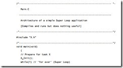
Listings 9.1 to 9.3 illustrate a simple embedded architecture, capable of running a single task (the function X()). After performing some system initialization (through the function Init_System()), the application runs the task ‘X’ repeatedly, until power is removed from the system.

Crucially, the ‘Super Loop’, or ‘endless loop’, is required because we have no operating system to return to: our application will keep looping until the system power is removed.

Hardware resource implications

SUPER LOOP has no significant hardware resource implications. It uses no timers, ports or other facilities. It requires only a few bytes of program code. It is impossible to create, in C, a working environment requiring fewer system resources.

Reliability and safety implications

Applications based on SUPER LOOP can be both reliable and safe, because the overall architecture is very simple and easy to understand and no aspect of the underlying hardware is hidden from the original developer or from the person who subsequently has to maintain the system. If, by contrast, you are programming for Windows or a similarly complex desktop environment (including Linux or Unix), you are not in complete control: if someone else wrote poor code in a library, it may crash your pro- gram. With a ‘super looping’ application, there is nobody else to blame. This can be particularly attractive in safety-related applications.

Please note, however, that just because an application is based on a Super Loop does not mean that it is safe. Indeed, in general, a Super Loop does not provide the facilities needed in an embedded application: in particular, it does not provide a mecha- nism for calling functions at predetermined time intervals. As we discussed in Chapter 1, these are key characteristics of most embedded applications: if you need such facili- ties, a scheduler (see Chapter 13) is almost always a more reliable environment.

Portability

Any ‘C’ compiler intended for embedded applications will compile a Super Loop program: the loop is based entirely on ISO/ANSI ‘C’. The code is therefore inherently portable.

Overall strengths and weaknesses

The main strength of Super Loop systems is their simplicity. This makes them (comparatively) easy to build, debug, test and maintain.

Super Loops are highly efficient: they have minimal hardware resource implications.

Super Loops are highly portable.

If your application requires accurate timing (for example, you need to acquire data precisely every 2 ms), then this framework will not provide the accuracy or flexibility you require.

The basic Super Loop operates at ‘full power’ (normal operating mode) at all times. This may not be necessary in all applications, and can have a dramatic impact on system power consumption. Again, a scheduler can address this problem.

Related patterns and alternative solutions

In most circumstances, a scheduler will be a more appropriate choice: see Chapter 13.

Example: Central-heating controller

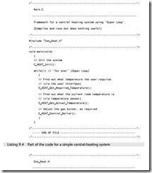
Suppose we wish to develop a microcontroller-based control system to be used as part of the central-heating system in a building. The simplest version of this system might consist of a gas-fired boiler (which we wish to control), a sensor (measuring room temperature), a temperature dial (through which the desired temperature is specified) and the control system itself (Figure 9.1).

We assume that the boiler, temperature sensor and temperature dial are connected to the system via appropriate ports. We further assume that the control system is to be implemented in ‘C’.

A rudimentary software  architecture-0164

A rudimentary software  architecture-0165

A rudimentary software  architecture-0166