Task-oriented design:Multi-state task

Multistate task

Context

● You are developing an embedded application using one or more members of the 8051 family of microcontrollers.

● The application has a time-triggered architecture, constructed using a scheduler.

Problem

How do you replace multiple tasks in an application with a single task that performs different activities depending on the current state of the system (and why is it, some- times, a good idea to do so)?

Background

See CO OPERA TIVE SCHEDULER [page 255] and MUL TI S TAT E TA S K [page 317] for relevant background information.

Solution

MUL TI S TAT E TA S K encapsulates a system architecture that is apparent in many well- designed embedded applications.

To understand the need for this architecture, consider a simple washing machine control system (Figure 16.4).

Here is a brief description of the way in which we expect the system to operate:

1 The user selects a wash program (e.g. ‘Wool’, ‘Cotton’) on the selector dial.

2 The user presses the ‘Start’ switch.

3 The door lock is engaged.

4 The water valve is opened to allow water into the wash drum.

5 If the wash program involves detergent, the detergent hatch is opened. When the detergent has been released, the detergent hatch is closed.

6 When the ‘full water level’ is sensed, the water valve is closed.

7 If the wash program involves warm water, the water heater is switched on. When the water reaches the correct temperature, the water heater is switched off.

8 The washer motor is turned on to rotate the drum. The motor then goes through a series of movements, both forward and reverse (at various speeds) to wash the clothes. (The precise set of movements carried out depends on the wash program that the user has selected.) At the end of the wash cycle, the motor is stopped.

9 The pump is switched on to drain the drum. When the drum is empty, the pump is switched off.

image

The description is simplified for the purposes of this example, but it will be ade- quate for our purposes here.

Based on this description we will try to identify some of the functions that will be required to implement this system. A provisional list might be as shown in Figure 16.5.

image

Now, suppose we wish to identify the tasks to be scheduled (co-operatively) in order to implement this application. Based on our list, it may be tempting to con- clude that each of the functions listed in Figure 16.5 should become a task in the system. While it would be possible to work in this way it would be likely to lead to a complex and cumbersome system implementation.

To see why this is so, take one example: the function Control_Water_Heater(). We want to heat the water only at particular times during the wash cycle. Therefore, if we want to treat this as a task and schedule it, say every 100 ms, we need to creation an implementation something like the following:

image

What this task does when it is executed is to check a flag: if it is necessary to heat the water, it starts to do so: otherwise, it stops the heating process.

There are two problems with creating the program in this way:

● We are going to end up with large numbers of tasks (very large numbers in a more substantial application), most of which – like this task – actually do very little. In applications without external memory this is a particular problem, because each task will consume some of the limited memory (RAM) resources.

● It is not at all clear which, if any, of these tasks will actually set the flag (Switch_on_water_heater_G), or the other similar flags that will be required in the other tasks in this application.

In practice, what we require in this and many similar applications is a single ‘System Update’ task: this, as we will see, is a task that will be regularly scheduled and will, where necessary, call functions such as Control_Water_Heater() as and when required.

In the washing machine, this system update task will look something like the code in Listing 16.1.

image

image

image

image

Listing 16.1 is a representative example of a MUL TI ST A TE T ASK .

We can describe the simplest form of this architecture as follows:

● The system involves the use of a number of different functions.

● The functions are always called in the same sequence.

● The functions are called from a single task, as required.

Note that variations on this theme are also common: for example, the functions may not always be called in the same sequence: the precise sequence followed (and the particular set of functions called) will frequently depend on user preferences or on some other system inputs.

Hardware resource implications

This architecture makes very efficient use of system resources.

Reliability and safety implications

There are no specific reliability or safety implications.

Portability

This high-level pattern is highly portable.

Overall strengths and weaknesses

MUL TI – ST AGE T ASK encapsulates a simple architecture that matches the needs of many embedded applications

Related patterns and alternative solutions

MUL TI ST AGE T ASK combined with ONE T ASK SCHEDULER [page 911] – and / or with ONE YEAR SCHEDULER [page 919] provides a very simple and efficient system architec- ture with minimal CPU, memory and power requirements.

Example: Traffic lights

Suppose we wish to create a system for driving three traffic light bulbs. The conventional ‘red’, ‘amber’ and ‘green’ bulbs will be used, with the usual sequencing (Figure 16.6).

Listing 16.2 shows how we can create a multi-state task to achieve this. The ‘Update’ function is intended to be scheduled every second.

image

image

image

image


Task-oriented design

Two patterns in this chapter encapsulate key design characteristics that underlie many successful co-operatively scheduled applications:

MUL TI ST AGE T ASK [page 317] considers techniques that may be used to convert long tasks (scheduled at infrequent intervals) into much shorter tasks (scheduled at frequent intervals)

MUL TI ST A TE T ASK [Page 322] considers techniques that may be used to replace multiple tasks with a single task that performs different activities depending on the current state of the system.


Task-oriented design:Multi-stage task

Multi-stage task

Context
● You are developing an embedded application using one or more members of the 8051 family of microcontrollers.

● The application has a time-triggered architecture, constructed using a scheduler.

Problem

How do you make sure that a long task does not interfere with the normal operation of the scheduler?

Background

See CO OPERA TIVE SCHEDULER [page 255] for relevant background information.

Solution
As we have seen, co-operative schedulers have many advantages when compared to pre-emptive or even hybrid schedulers and we generally wish to use a co-operative approach when it is feasible to do so. However, a key design challenge when using this approach is to ensure that each task is completed before the next scheduler tick occurs. One approach that can help us to achieve this goal is to make use of timeouts (see Chapter 15).

Another approach is to use of multi-stage tasks. To understand the need for multi- stage tasks, consider an example (adapted from Pont 1996,Chapter 13). Suppose that as part of a ‘backup’ temperature monitoring system for a metal furnace we are required to send temperature samples at regular, 5-second, intervals to a desktop PC (Figure 16.1).

The required PC output takes the form shown in Figure 16.2.

At first inspection, the obvious way of sending this information to the PC at the required 5-second interval is to create a function (we will call it Send_Temp_Data()), which will be run by the scheduler every five seconds.

However, this is probably a rather bad solution. The problem is that we need to send at least 43 characters to the PC using Send_Temp_Data(). At a common baud rate of 9,600 (see Chapter 18 for details), each of the characters will take approxi- mately 1 millisecond to send: as a result, the task duration will be around 40 ms. If we use this (long) task, we will need to set the system tick interval at a value greater than 40 ms, which may have a detrimental impact on the overall responsiveness of the application.

image

The multi-stage alternative solution avoids this problem. Rather than sending all the data at once, we can simply store the data we want to send to the PC in a buffer. Every ten milliseconds (say) we schedule a task to check the buffer and send the next character (if there is one ready to send). In this way, all the required 43 characters of data will be sent to the PC within 0.5 seconds: we can reduce this time if necessary (it rarely is) by scheduling the task to check the buffer every millisecond. Note that because we do not have to wait for each character to be sent, the process of sending data from the buffer will be very fast (typically a fraction of a millisecond).

Overall, the use of multi-stage tasks in this application allows us the opportunity to use a much shorter tick interval and therefore make more efficient use of the microcontroller’s processing power.

The ‘RS232’ library used as an example here is discussed in detail in Chapter 18.

Hardware resource implications

In general, the use of multi-stage tasks allows much more efficient use of the available microcontroller processing power.

Reliability and safety implications

Use of multi-stage tasks can make your system more responsive, by allowing the user of a shorter tick interval.

Portability

This technique can be (and is) applied in a wide range of different embedded systems.

Overall strengths and weaknesses

The use of multi-stage tasks allows the use of shorter tick intervals and, hence, can help to make the system more responsive.

The use of multi-stage tasks allows much more efficient use of the available microcontroller processing power.

Related patterns and alternative solutions

This basic architecture is applied in various patterns in this collection, including PC LINK (RS -232 ) [page 362], LCD CHARACTER P ANEL [page 467] and SWITCH INTER F ACE ( SOFTW ARE ) [page 399].

Example: Measuring rotational speed
Suppose we wish to measure the speed of a rotating shaft and display the results on a (multiplexed) LED display. This could be part of an automotive or industrial application.

As we will see in Chapter 30, an effective way of measuring the speed is to attach an appropriate rotary encoder to the shaft (Figure 16.3), and count the number of pulses that occur over a fixed period of time (say 100 ms or 1 second). From the count, and having details of the rotary encoder, we can calculate the average speed of rotation.

image

We have seen various people try to apply this basic approach in a scheduled envi- ronment as follows:

● Create a task of (say) 100 ms duration

● In this task, count the pulses

● Set the value of a (global) Pulse_count_G variable at the end of the task

● Use the global variable to update the LED display

The problem with this approach is that 100 ms taken to measure the speed is a long task duration and can be difficult to support in many embedded applications. Here, for example, we suggested that we wished to display the speed on a multiplexed LED display. We might well have to update the LEDs every 5 ms to avoid flickering (see MX LED DISPLA Y [page 450] for details).

Of course, a co-operative scheduler cannot support tasks called every 5 ms and tasks of 100 ms duration.

To solve this problem, consider a multi-stage approach to this problem. In the first approach, we waited in the task to count the pulses from the encoder. However, this is not necessary. Timer 0 or Timer 1 (or Timer 2 where available) will count pulses (strictly, falling edges of pulses) on external pins without user intervention, without generating interrupts and without interfering with any other processing. We can use this fact to make this speed measurement system into a multi-stage task as follows:

● Create a very short (<0.1 ms task)

● Schedule this task (say every 100 ms, to be compatible with the first example)

● In this task, read the current pulse count. Store the result in a global variable (for use elsewhere in the program)

● Reset the pulse count to 0

● Repeat 100 ms later etc.

The details of the technique will be considered in Chapter 30, where we will see that it is possible for similar solutions to be created without the need for the timer hardware.

Example: LCD library

Suppose we wish to update an LCD display. As we will see in LCD CHARACTER P ANEL [page 467], updating each character in a typical LCD display can take around 0.5 ms: to update the whole of a 40-character display can therefore take around 20 ms. This is often prohibitively long.

However, suppose we schedule a LCD_Update() function every 20 ms and, each time, update only a single display position. At worst, it will take us a total of 800 ms to update the whole display – and we will be able to complete numerous other tasks at the same time. In addition, in most circumstances, only some of the display will have changed: if we keep track of characters that need to be updated, we can usually keep the display fully up to date with a multi-stage task of 0.5 ms duration called every 100 ms. Overall, the multi-stage approach to this single task can make a major difference to the architecture of the whole application.


Delays

Introduction

The creation of accurate delays are key requirements in many embedded applications.

In this chapter we will consider two different techniques that may be used to pro- vide such facilities:

HARDW ARE DELA Y [page 194] which is capable of producing precise delays through the use of one of the on-chip timers. Particularly suitable for generating delays of around 0.1 ms or more.

SOFTW ARE DELA Y [page 206] which is a simple technique that requires no hardware resources. The most flexible form of delay mechanism that is particularly suitable for generating short delays (measured in microseconds) or where timer resources are not available.


Using the ports:Port header

Port header
Context

● You are developing an embedded application using one or more members of the 8051 family of microcontrollers.

Problem

How do you manage port access allocations in a larger project?

Background

In a typical embedded project, you may have a user interface created using an LCD, a keypad and one or more single LEDs. There may be a serial (RS-485) link to another microcontroller board. There may be one or more high-power devices (say three- phase industrial motors) controlled by your application.
Each of these (software) components in your application will require exclusive access to one or more port pins. The project may include 10–20 different source files. How do you ensure that changes to port access in one component do not impact on another? How do you ensure that it is easy to port the application to an environment where different port pins must be used?

These issues are addressed through the simple PORT HEADER design pattern.

Solution

P ORT H EADER encapsulates a simple but effective design guideline that can help you cope with the fact that many different components in a larger project will each require port access: specifically, using P ORT H EADER , you will pull together the differ- ent port access features for the whole project into a single (header) file. Use of this technique can ease project development, maintenance and porting.

Port Header is simple to understand and simple to apply.

Consider, for example, that we have three C files in a project (A, B, C), each of which requires access to one or more port pins, or to a complete port.

Using the ports-0180

In this version of the code, all of the port access requirements are spread over mul- tiple files. Instead of this, there are many advantages obtained by integrating all port access in a single Port.H header file:

Using the ports-0181

Listing 10.4 An example of a real Port Headerfile (Port.H) from a project using an interface consisting of a keypad and liquid crystal display

Hardware resource implications

There are no hardware resource implications.

Reliability and safety implications

Despite its simplicity, Port Header can improve reliability and safety, because it avoids potential conflicts between port pins, particularly during the maintenance phase of the project when developers (who may not have been involved in the original design) are required to make code changes.

Portability

Port Header is itself portable: it can be used with any microcontroller and is not linked to the 8051 family. Use of Port Header also improves portability, by making accessible in one location all the port access requirements of the application.

Overall strengths and weaknesses

PORT HEADER is both simple and effective – use it!

Related patterns and alternative solutions

See PROJECT HEADER [page 169].

Example: LED bargraph display

Suppose we wish to test an application involving an analog-to-digital converter. Specifically we want to display the voltage reading on a set of 8 LEDs connected to Port 1 of our 8051 device (Figure 10.2).

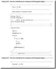
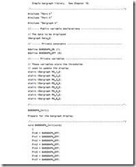
The key software files required to create this application follow (Listings 10.5 to 10.8): a complete set of the source files for the project is included on the CD.

Using the ports-0182Using the ports-0183Using the ports-0184Using the ports-0185Using the ports-0186Using the ports-0187Using the ports-0188


Using the ports:Port I/O

Port I/O
Context

● You are developing an embedded application using one or more members of the 8051 family of microcontrollers.

● You are designing an appropriate software foundation for your application.

Problem

How do you write software to read from and /or write to the ports on an (8051) microcontroller?

Background

The Standard 8051s have four 8-bit ports. All of the ports are bidirectional: that is, they may be used for both input and output.

To limit the size of the device, some of the port pins have alternative functions. For example, as we saw in Chapter 6, Ports 0, 2 (and part of Port 3) together provide the address and data bus used to support access to external memory. Similarly, two fur- ther pins on Port 3 (pins 0 and 1) also provide access to the on-chip USART (see Chapter 18). When in their ‘alternative roles’, these pins cannot be used for ordinary input or output. As a result, on the original members of the 8051 family, where exter- nal memory is used, only Port 1 is available for general-purpose I/O operations.

These comments all refer to the Standard 8051: the number of available ports on 8051 microcontrollers varies enormously: the Small 8051s have the equivalent of approximately two ports and the Extended 8051s have up to ten ports (see Chapter 3). Despite these differences, the control of ports on all members of the 8051 family is carried out in the same way.

Solution

Control of the 8051 ports through software is carried out using what are known as ‘special function registers’ (SFRs). The SFRs are 8-bit latches: in practical terms, this means that the values written to the port are held there until a new value is written or the device is reset.

Each of the four basic ports on the Standard 8051 family, as well as any additional ports, is represented by an SFR: these are named, appropriately, P0, P1, P2, P3 and so on. Physically, the SFR is a area of memory in the upper areas of internal RAM: P0 is at address 0x80, P1 at address 0x90, P2 at address 0xA0 and P3 at address 0xB0.

If we want to read from the ports, we need to read from these addresses. Assuming that we are using a C compiler, the process of writing to an address is usually by  means of a SFR variable ‘declaration’, hidden in a header file. Thus, a typical SFR header file for an 8051 family device will contain the lines:

A rudimentary software  architecture-0171

In general, we use initialization functions to set the ports to a known state at the start of the program. Where this is not possible, it is safer to always write ‘1’ to any port pin before reading from it, as was illustrated in the first example.

Note that, in the last example, we assume that we wished to read from or write to an entire port. More commonly, we might wish (for example) to control an LED is connected to a single output pin. For example, assuming that the LED is connected to Pin 0 on Port 3 of an 8051-family microcontroller, we can flash the diode by control- ling the whole port, as follows:

A rudimentary software  architecture-0172

Alternatively, we can make use of an sbit variable in the C51 compiler to provide a finer level of control. At the same time, we consider the fact that – depending on the hardware (see Chapter 7) – the LED may be lit using a logic 1 or a logic 0 output on the port pin and we make the software flexible enough to deal easily with subse- quent hardware changes:

A rudimentary software  architecture-0173

Reliability and safety implications

Port reset values

After the system is reset, the contents of the various port special function registers (SFRs) are set to 0xFF. This fact has very important safety and reliability implications.

Consider, for example, that you have connected a motorized device to a port and that the device is activated by a ‘logic 1’ output. When the microcontroller is reset, the motorized device will be activated. Even if you change the port outputs to 0 at the start of your program, the motor will be ‘pulsed’ briefly. This can, in some systems, lead to the injury or even death of users of the system or those in the immediate vicinity.

Because the output pins are ‘reset high’ it is important to ensure that any devices which have safety implications are connected to the microcontroller in such a way

that they are ‘active low’: that is, that an output of ‘0’ on the relevant port pin will activate the device.

Port I/O and memory access

One of the most common errors made by inexperienced 8051 developers is to con- tinue to use P0, P2 or P3 as normal I/O ports when using external memory (see Chapter 8 for details of memory usage).

If you use external memory, you cannot safely use P0 and P2 for any other purpose and you must also take care when writing to Port 3.

For example, any statement similar to this:

P3 = AD_data;

is potentially catastrophic if external memory is being used.

Instead, make use of sbit variables to ensure you only write to ‘safe’ port pins (see ‘Example: Reading and writing bits’ for details).

Hardware resource implications

All port I/O involves the use of port pins. As we discussed earlier, if these pins are used for I/O, then they are not generally available for other purposes.

Note that all Extended 8051s provide additional ports. On the 80C515C, for exam- ple, there are eight 8-bit ports: these include the ‘standard’ ports (0–3), plus one 8-bit port with alternate A/D conversion functions and three further ports.

Portability

Port access in general and the keywords bit and sbit in particular are not part of the ISO / ANSI C language: therefore, by definition, this code is not totally portable.

That said, this code can be used (with the standard Keil compiler) across the whole of the 8051 range. With minor modifications it can be used with other 8051 compil- ers, all of which provide similar facilities.

Overall strengths and weaknesses

This pattern allows flexible and efficient access to the 8051 ports, making full use of the internal BDATA memory area (discussed in Chapter 6).

As noted earlier, port access in general and the keywords bit and sbit in particular are not part of the ISO / ANSI C language: therefore, by definition, this code is not totally portable. Note that, while perhaps less than ideal, this problem cannot be avoided.

Related patterns and alternative solutions
Hardware issues

This pattern does not deal with external hardware: see Part A (particularly Chapters 7 and 8) and Part C for patterns that cover these issues.

Interrupt inputs

For reasons discussed in Chapter 1, we make very limited use of interrupt inputs in this book.

Example: Reading and writing bytes

Listing 10.1 illustrates how we can read from a collection of eight switches connected to a port on an 8051-family microcontroller and ‘echo’ these switch settings on an output port: using SWITCH INTERF ACE ( SOFTW ARE ) [page 399], NAKED LED [page 110] and IC BUFFER [page 118] we could, for example, use this code to display the switch settings on a panel of LEDs.

Note, however, that you do not require any hardware to try out this code: the Keil hardware simulator (included on the CD) allows you to simulate suitable hardware. Figure 10.1 shows the output from one such simulation.

Using the ports-0174

Using the ports-0175

Example: Reading and writing bits

Listing 10.1 demonstrated how to read from or write to an entire port. Consider another common problem: reading and writing individual pins on a port. This prob- lem arises because often the various parts of a port will be serving different purposes.

Suppose, for example, that we have a switch connected to Port 1 (pin 3) and an LED connected to Port 1 (pin 4) and also have other input and output devices con- nected to the other pins on this port. How do we read from pin 3 and write to pin 4 without disrupting anything else?

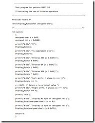
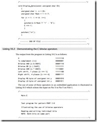
We can do this by making use of the bitwise AND, OR and ‘complement’ operators. These, and other, bitwise operators are not widely used by desktop developers. The various bitwise operators allow a number of data manipulations that are invaluable in embedded applications. Some examples of the use of these operators are given in Listing 10.2. Note that this file is written in ISO ‘C’ (’Desktop C’): it cannot be run on the Keil compiler.

Using the ports-0176

The use of some of these operators in an embedded application is illustrated in Listing 10.3 which echoes the input on Pin X to Pin Y on Port 1.

Using the ports-0177

Example: Displaying error codes in a scheduler

See CO OPERA TIVE SCHEDULER [page 255], where error codes are displayed on a bank of LEDs connected to a port.

Example: Controlling an LCD

See LCD CHARACTER P ANEL [page 467], where control of individual port pins is used to send data to an LCD panel.

Further reading

Further information about the use of the ‘C’ bitwise operators will be found in any standard textbook on C programming.


Delays:Software delay

Software delay
Context

● You are developing an embedded application using one or more members of the 8051 family of microcontrollers.

● You are designing an appropriate software foundation for your application.

Problem

How do you create a simple delay without using any hardware (timer) resources?

Background

See HARDW ARE DELA Y [page 194] for background information.

Solution

Suppose we want to flash the LEDs connected to Port 1 on an 8051 microcontroller with a two second cycle time (so that they are on for 1 second then off for 1 second, ad infinitum). The basic program structure we require could be based on a SUPER LOOP [page 162] as follows:

Delays-0198

We could then measure the pulse frequency we obtained, using an oscilloscope or a software simulator. If we found that these delays were not long enough, we could easily extend them by adding additional layers, as shown in Longer_Loop_Delay()

Delays-0199

Hardware resource implications

Unlike HARDW ARE DELA Y [page 194], SOFTW ARE DELA Y uses no timer resources. Note, however, that the CPU time spent in the delay calculation is wasted: using a sched- uler (see Chapter 13) can, in many circumstances, avoid the waste of CPU time.

Reliability and safety implications

Software delays are not suitable for use in applications where precise timing is required.

Portability

Software delays can be used even on a microcontroller / microprocessor without a built-in timer. However, the precise delay duration obtained varies (enormously) with differences in hardware and software.

Overall strengths and weaknesses

SOFTW ARE DELA Y can be used to produce very short delays.

SOFTW ARE DELA Y requires no hardware timers.

SOFTW ARE DELA Y will work on any microcontroller.

It is very difficult to produce precisely timed delays.

The loops must be returned if you decide to use a different processor, change the clock frequency or even change the compiler optimization settings.

Related patterns and alternative solutions

In most circumstances, it is better to avoid using delays at all: see CO OPERA TIVE SCHED ULER [page 255] for a delay-free alternative that will work in many circumstances.

If you do require delays then HARDW ARE DELA Y [page 194] is often a better alternative.

Example: Creating a 5 µs delay in an I2C library

As we discuss in Chapter 23, software implementation of the I2C serial protocol can require small delays. In Listing 11.5 we illustrate how a delay of around 5 µs can be created in software for use in such a library.

Delays-0200

Listing 11.5 Creating a very short delay

Example: Flashing an LED

We will repeat the ‘flashing LED’ example used in HARDW ARE DELA Y [Page 194] to illustrate the SOFTW ARE DELA Y pattern.

To control the flashing of the LED, we will use an endless loop involving one SOFT W ARE DELA Y and a ‘flash LED’ function.

We assume that we are using a Standard 8051 device with 12 oscillations per instruction cycle and an oscillator frequency of 12 MHz. (see Chapter 4 for further details.)

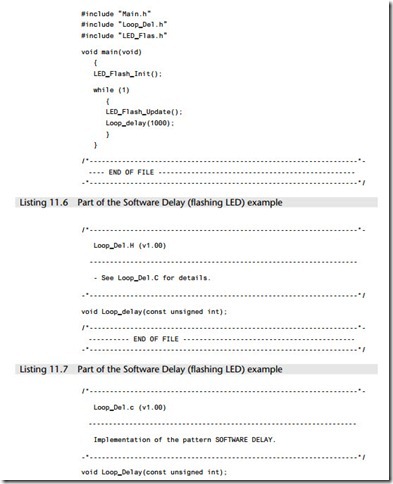
The key files required in the project follow (Listings 11.6 to 11.11). As usual complete set of files are included on the CD.

Delays-0201Delays-0202Delays-0203Delays-0204Delays-0205Delays-0206Delays-0207


Watchdogs:Hardware watchdog

Hardware watchdog
Context

● You are developing an embedded application using one or more members of the 8051 family of microcontrollers.

● You are designing an appropriate software foundation for your application.

Problem

How can you ensure that – if your application ‘hangs’ due to an unexpected software or hardware error – the system will automatically reset itself?

Background

See the introduction to this chapter for an explanation of the watchdog analogy.

Solution

Working with HARDW ARE W A TCHDOG means using either an internal or external (hard- ware) timer.

We have seen in many previous cases that, where available, the use of on-chip components is to be preferred to the use of equivalent off-chip components. Specifically, on-chip components generally offer the following benefits:

● Reduced hardware complexity, which tends to result in increased system reliability.

● Reduced application cost.

● Reduced application size.

In the case of watchdog timers, the situation is more complex, because external watchdog chips typically provide some useful facilities that are not available in most on-chip versions.

For example, the popular ‘1232’ watchdogs (available, in various versions, from Dallas Semiconductors, Maxim, Linear Technology and Analog Devices) are low-cost, low-power devices. In addition to functioning as a watchdog timer, they also provide power system monitoring capabilities (see ROBUST RESET [page 77] for details of this). If, as in many designs, you intend to use an external ‘robust reset’ circuit anyway, then the 1232 chips allow you to incorporate an external watchdog facility for mini- mal addition cost and only a very minor increase in hardware complexity.

Another beneficial feature of external watchdogs is that they are inherently portable: you can generally use the same external watchdog with any member of the 8051 family. By contrast, code written to work with an internal watchdog will gener- ally have to be rewritten for use with a different hardware.

One situation in which on-chip watchdogs (such as those in the Infineon c515x devices) can be beneficial is where they allow you to determine whether the system has undergone a normal reset or a reset caused by a watchdog overflow. This may allow you to modify the system behaviour to match these circumstances. Without this information (which is not generally available through external watchdogs with- out some complex coding) your system may be continually reset by the watchdog timer overflow.

We can summarize by saying that, if you require watchdog facilities, you need to consider both internal and external solutions carefully. There is no single ‘ideal’ solu- tion and – considering the issues mentioned earlier – you need to find the best match to your requirements.

Reliability and safety implications

Before using either an internal or external watchdog, you need to be sure that the use of such a timer will increase (rather than decrease) the reliability of your application.

The first thing to bear in mind is that watchdog behaviour should be for disaster recovery. In a well-designed system the occurrence of a watchdog reset should be a noteworthy event that occurs rarely. If you think of the use of watchdogs in terms of ‘if all else falls, then we will have to let the watchdog reset the system’, then you are taking a realistic view of the capabilities of this approach.

Used without due care at the design phase and/or adequate testing, watchdogs can reduce the system reliability dramatically. A particular problem with a badly designed watchdog can occur in the presence of sustained hardware faults. In these circum- stances, a badly implemented watchdog can mean that your system constantly resets itself. This can be extremely dangerous.

You also need to appreciate that watchdogs are unsuitable for many applications, because the time taken to react to an error is too long. Suppose, for example, the braking system in an automotive application uses a 500 ms watchdog and the vehicle encounters a problem when it is travelling at 70 miles per hour (110 km per hour). In these circum- stances, the vehicle and its passengers will have travelled some 16 yards / 15 metres – right into the car in front – before the vehicle even begins to reset the braking system. In short, where fast recovery is required, watchdogs are rarely the best solution.

Portability

As already noted, internal watchdogs are based on hardware that is not part of the 8051/52 core. As a result, different forms of watchdog now exist on the various differ- ent 8051 derivatives and code written for one on-chip watchdog will generally need to be adapted for use with a different device. By contrast, software written for external watchdogs can be more portable.

Overall strengths and weaknesses

Watchdogs can provide a ‘last resort’ form of error recovery. If you think of the use of watchdogs in terms of ‘if all else fails, then reset the system’, then you are taking a realistic view of the capabilities of this approach.

In the presence of intermittent faults, e.g. rare bursts of EMI, watchdogs can be very effective.

Watchdogs with long timeout periods are unsuitable for many applications.

Used without due care at the design phase and / or adequate testing, watchdogs can reduce the system reliability dramatically.

In the presence of sustained hardware faults, badly implemented watchdogs can mean that your system constantly resets itself. This can be very dangerous.

Related patterns and alternative solutions

In certain restricted circumstances, a software watchdog may also be useful.

This can be created from two components:

● A timer ISR

● A refresh function

Essentially, we set a timer to overflow in (say) 60 ms. Under normal circumstances, this timer will never overflow, because we will call the refresh function regularly and thereby restart the timer. If, however, the program is ‘jammed’, the refresh function will not be called. When the timer overflows, the ISR will be called: this will imple- ment an ‘appropriate’ error recovery strategy.

We have used software watchdogs in several applications. The main problem with this approach is that some software errors (for example, those induced by EMI) can disrupt the watchdog timer as well as the main application code: this rarely happens with hardware watchdogs, which tend to be more robust.

The main advantage with software watchdogs is that different forms of error recov- ery (not just a complete chip reset) are possible. However, use of an on-chip hardware watchdog can provide flexible reset behaviour and is, in many circumstances, a more reliable solution.

Example: Using the ‘1232’ external watchdog timer

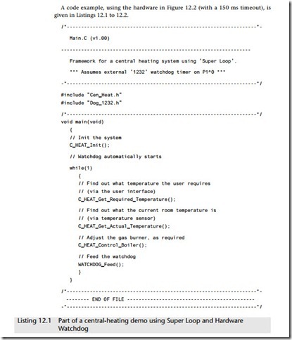
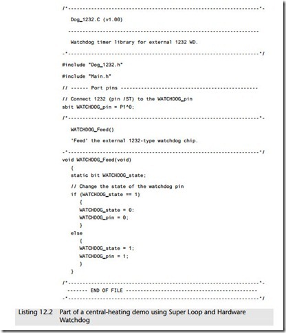
In this example we assume that we will be developing a simple central-heating con- trol system and will be using an external ‘1232’ watchdog chip to improve the reliability of the application.

The use of the 1232 is very straightforward:

● We wire up the watchdog to the microcontroller reset pin, as illustrated in Figure 12.2.

Watchdogs-0209

● We choose from one of three (nominal) possible timeout periods, and connect the TD pin on the 1232 to select an appropriate period (see Table 12.1).

● We pulse the ST line on the 1232 regularly, with a pulse interval less than the time- out period.

Watchdogs-0210Watchdogs-0211

Watchdogs-0212

Example: Using the internal watchdog timer on the Atmel 89S53

The Atmel 89S53 is an example of a Standard 8051 microcontroller with a good on-chip watchdog timer.

A key feature of this timer is that it operates from an independent oscillator: as a result, it allows the system to respond to (intermittent) failures of the main crystal oscillator or resonator.

The key register used to control the watchdog timer is the WCON register, shown in Table 12.2.

Watchdogs-0213

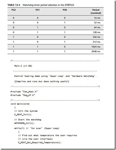
The prescaler bits, PS0, PS1 and PS2 in SFR WCON are used to set the period of the Watchdog Timer from 16 ms to 2048 ms. The available timer periods are shown in Table 12.4 and the actual timer periods (at Vcc = 5V) are within ±30% of the nominal.

The WDT is disabled by power-on reset and during power-down. It is enabled by setting the WDTEN bit in SFR WCON (address = 96H). The WDT is reset by setting the WDTRST bit in WCON. When the WDT times out without being reset or disabled, an internal RST pulse is generated to reset the CPU.

Listings 12.3 to 12.7 how we might use this watchdog in the simple central-heating system discussed in the previous example.

Watchdogs-0214

Watchdogs-0215Watchdogs-0216Watchdogs-0217


An introduction to schedulers

In this chapter, we see that schedulers can play a similar role in embedded systems to that played by ‘Windows’ (or other operating systems) in many modern desktop applications.

Introduction

Having laid the foundations in Parts A and B, we are now in a position to look in detail at the ways in which time-triggered applications may be created with the 8051 family of microcontrollers.

To produce such applications, we will use a scheduler: this is a very simple operating environment for embedded applications. In this introductory chapter, we explain what a scheduler is and the differences between co-operative and pre-emptive scheduling. We will also explain why the use of a co-operative scheduler can help to make even the smallest of embedded applications easier to develop and more reliable in operation.

To place the discussions in the rest of the chapter in context, we begin by briefly reviewing the reasons why desktop systems employ an operating system and explain- ing why such an OS is not appropriate for use with the type of embedded systems considered in this book.


Watchdogs

Introduction

Suppose there is a hungry dog guarding a house (Figure 12.1), and someone wishes to break in. If the burglar’s accomplice repeatedly throws the guard dog small pieces of meat at 2-minute intervals, then the dog will be so busy concentrating on the food that he will ignore his guard duties and will not bark. However, if the accom- plice run out of meat or forgets to feed the dog for some other reason, the animal will start barking, thereby alerting the neighbours, property occupants or police.

Watchdogs-0208

This same basic approach is followed in computerized ‘watchdog timers’. Very simply, these are timers which, if not refreshed at regular intervals, will overflow. In most cases, overflow of the timer will reset the system. Such watchdogs are intended to deal with the fact that, even with meticulous planning and careful design, embed- ded systems can ‘hang’ due to unexpected problems. The use of a watchdog can be used to recover from this situation, in certain circumstances.

The pattern HARDW ARE W A TCHDOG [page 217] considers how to apply these tech- niques to good effect in your embedded application.