Using serial peripherals

Using serial peripherals

In Part E we consider how two powerful and influential serial communication protocols (‘I2C’ and ‘SPI’) may be utilized in applications with a time-triggered architecture.

Use of these protocols has two main advantages:

● They are designed to allow microcontrollers to be linked to a wide range of different peripherals – memory, displays, ADCs and similar devices – without requiring the use of large numbers of port pins.

● A common set of software code may be used with all SPI peripherals (for example), reducing the development effort required.

In Chapter 23, we consider the I2C bus, developed by Philips. I2C is a simple protocol, and may be easily generated in software. This allows the full range of 8051 devices (including Small 8051s, with very few spare port pins) to communicate with a wide range of peripheral devices.

In Chapter 24, we consider the SPI bus, developed by Motorola. Increasing numbers of ‘Standard’ and ‘Extended’ 8051 devices have hardware support for SPI and we will make use of these facilities in Chapter 24.


Example: Displaying elapsed time on a multiplexed (4-digit) LED display

Example: Displaying elapsed time on a multiplexed (4-digit) LED display

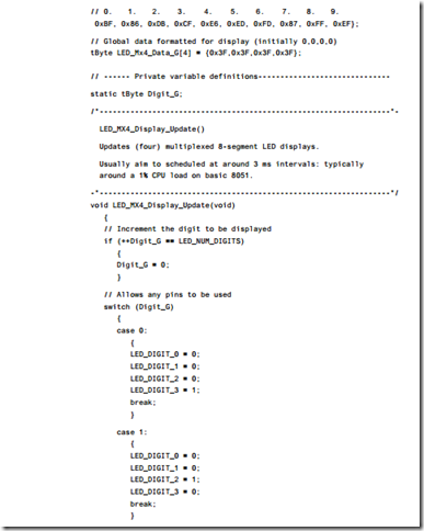
A common use for LED displays is to display the time. This simple example demon- strates the display of elapsed time on four multiplexed LEDs. The code is written for a standard 8051 (8052) device.

The required hardware is illustrated in Figure 21.6.

The key source files for this example follow (Listings 21.2 to 21.5): all the files required in this example are included on the CD.

image

image

image

image

image

image

image


Multiplexed LED displays:Mx led display

Introduction

Many embedded applications contain user interfaces assembled from multi-segment LED displays.

In this chapter, we consider how such displays may be interfaced to the 8051 family of microcontrollers.

Mx led display

Context

● You are developing an embedded application using one or more members of the 8051 family of microcontrollers.

● The application has a time-triggered architecture, constructed using a scheduler.

● You are creating the user-interface for your application.

Problem

How do you display information on one or more multi-segment LED displays?

Background

We consider some essential background material in this section.

What is a multi-segment LED?

Multiple LEDs are often arranged as multi-segment displays: combinations of eight segments (see Figure 21.1) and similar seven-segment displays (without a decimal point) are particularly common.

Such displays are arranged either as ‘common cathode’ or ‘common anode’ pack- ages: the connection of the LEDs within each package is illustrated in Figure 21.2.

In either case, in addition to the common pin, we must provide appropriate signals to each of the LEDs in order to generate the digits we require (see ‘Solution’).

The required current per segment varies from about 2 mA (very small displays) to about 60 mA (very large displays, 100mm or more).

image

image

Basic hardware requirements (driving a single digit)

For reasons that we discussed in IC BUFFER [page 118], we cannot generally connect a multi-segment LED directly to a microcontroller port as illustrated in Figure 21.3. As you will recall, this is because the port cannot safely handle the required current (typically around 80 mA per digit).

In most cases, we require some form of buffer or driver IC between the port and the MS LED.

For small displays (around 9 mA per segment), the simple 240 and 241 buffers (see IC BUFFER [page 118]) are a cost-effective solution. Figure 21.4 shows a 74×241 (non- inverting buffer) used to drive a single, eight-segment LED display. Note that a 74×240 (inverting) buffer can be used as an alternative.

In most circumstances (such as the multiplexed displays we will focus on here), the basic 240 / 241 buffers have insufficient current capacity and an IC driver chip will generally be used. For example, Figure 21.5 shows a single common cathode LED digit connected to a single port via another octal buffer: the UDN2585A. As we discussed

image

image

in IC DRIVER [page 134], each of the (eight) channels in this device can simultane- ously source up to 120 mA of current (at up to 25V): this is enough, for example, for even the largest of LED displays.

Here, the output of the 2585 in response to a Logic 0 input will be approximately Vcc. As a result, the resistor values are again calculated as shown in Figure 21.4.

Hardware for multiple digits

As discussed in ‘Background’, driving a single multi-segment display is straightfor- ward. Suppose, however, that we need to drive four digits, perhaps for a simple digital clock. To do so using the approach discussed in ‘Background’ would require four spare ports. In many applications, you will not have four ports available. In addition, to use four ports often requires a separate driver (buffer) circuit and resistor pack for each digit: this can significantly increase the system cost.

The most common solution, discussed here, is to multiplex the displays. This means that (in this example) we drive each display for only a quarter of the time: as long as we cycle around all of the displays at between 20 and 50 Hz, the user will not generally notice that the displays are not being simultaneously driven. Even with a simple imple- mentation, this basic approach allows us to drive up to eight LEDs (each with decimal points) using only two ports. More commonly, this allows us to drive four LED digits using 12 port pins. As in many 8051 applications (even those using external memory) Port 1 and most of Port 3 are available, this approach can be used in many applications.

A simple circuit suitable for creating a cost-effective multiplexed display is shown in Figure 21.6. Here, the information required to drive each digit is supplied on Port X, while the selection of the digits is controlled by Port Y.

Note that Port Y must control (sink) the current coming from eight individual LEDs: this may be up to around 140 mA, even for a collection of small displays and

image

can approach 500 mA for large (100 mm) displays. As a result, we cannot directly drive the displays from a port, but must use, for example, a ULN 2003 or 2803 as a (sink) buffer. Note that you can replace the 2003 / 2803 (or equivalent) with four NPN transistors (e.g. 2N2222), but this is seldom cost-effective.

You will also need a buffer on Port X to source sufficient current: the UDN 2585A is, again, a good choice here. Use of such a source buffer is often essential, since – to achieve a bright display – we usually supply up to four times the normal display cur- rent, for a quarter of the time (thus keeping the average current at the required value). Your microcontroller will have a greatly reduced life if you try to provide this current from the naked chip.

Again, the values of R in Figure 21.6 are calculated as shown in Figure 21.4. In this case, it can be helpful to use a ‘resistor pack’ to implement the circuit: such packs contain seven or eight resistors, in a standard (dual in line: DIL or similar) package.

Solution

We consider here both the software codes required to display digits on the display and the refresh rates needed for flicker-free operation.

Basic software

The software to control the LED digits in arrangements like those shown in Figures21.4 and 21.5 is easy to write. If, for example, we connect the display to Port 3, we can control it by simply writing:

image

image

Controlling more than one digit per port (Software issues)

We need to update all the displays at a rate of approximately 50 Hz, if we can: if nec- essary, rates as low as 20 Hz will do. If we have N LED modules, each will be active for approximately 1/N of the time. Note that, if you choose to drive the displays at high current values, the timing needs to be reasonably accurate, otherwise you may reduce the life of the display and driver components by exposing them to excessively high currents for sustained periods.

Overall, for a typical four-module display, we aim to update one module at least every 5 milliseconds. This is easy to achieve using a suitable scheduler, as we demon- strate in the examples that follow.


Controlling LCD panels:Lcd character panel

Lcd character panel

Context

● You are developing an embedded application using one or more members of the 8051 family of microcontrollers.

● The application has a time-triggered architecture, constructed using a scheduler.

● You are creating the user interface for your application.

Problem

How do you connect an LCD-based ‘character panel’ display to your embedded processor and control it efficiently using a high-level programming language?

Background

As outlined at the start of this chapter, we are concerned here with LCD character panels based on the HD44780 microcontroller.

Key HD44780 components

The HD44780 contains its own reset circuitry, memory and so forth: it contains sev- eral important components (Figure 22.1), which may be accessed and controlled from an attached microcontroller or microprocessor. We will discuss some of the key com- ponents in the sections that follow.

As shown in Figure 22.1, the interface between the microcontroller and the HD44780 consists of five sets of signals. A summary of each of these signals is given in Table 22.1.

DD RAM

At the heart of the HD44780 is the DD RAM: the ‘Display Data’ RAM. This stores dis- play data represented in 8-bit character codes. Its capacity is 80 characters; as a result the maximum display sizes are 20 charactersx4 lines or 40 charactersx2 lines.

Use of the HD44780 involves transferring data (via the 4-bit or 8-bit data bus) into the DD RAM. The HD44780 will then refresh the display as required using these data.

Characters that can be stored and displayed via DD RAM include most of the core (displayable) characters from the ASCII table, with only minor changes (Table 22.2): this means that, in general, you can simply send character data to the display and obtain the expected outputs.

Note that none of these characters uses the bottom line of the display (the cursor line): as a result, low-case characters with ‘tails’ (g, j, p, q, y) will appear higher than normal on the display.

image

image

CG RAM

The CG RAM is the ‘Character Generator’ RAM: this can be used to allow the creation and display of user-defined characters. This facility is helpful if you wish to display characters outside the ‘standard’ range, such as a ‘£’ sign.

We demonstrate how to use CG RAM in an example that follows.

Registers

The HD44780 has two 8-bit registers, an instruction register (IR) and a data register (DR):

● The IR stores instruction codes, such as display clear and cursor shift and address information for DDRAM and character generator CGRAM.

● The DR temporarily stores data to be written into DDRAM or CGRAM. Data written into the DR from the 8051 are automatically written into DDRAM or CGRAM by an internal operation.

Busy flag (BF)

When the busy flag is 1, the HD44780 is performing an internal operation and fur- ther instructions or data will not be accepted. When RS = 0 and R/W = 1 (Table 22.4), the busy flag is output to DB7.

image

Cursor/blink control circuit

As the name suggests, the cursor/blink control circuit generates the cursor or character blinking. The cursor or the blinking will appear with the digit located at the display data RAM (DDRAM) address set in the address counter (AC). For example, when the address counter is 0x08, the cursor position is displayed at DDRAM address 0x08.

Address counter (AC)

The address counter (AC) assigns addresses to both DDRAM and CGRAM. When an address of an instruction is written into the IR, the address information is sent from the IR to the AC.

Selection of either DDRAM or CGRAM is also determined concurrently by the instruction.

After writing to DDRAM or CGRAM, the AC is automatically incremented by 1. The AC contents are then output to DB0 to DB6 when RS = 0 and R/W = 1 (Table 22.4).

Solution

As discussed in ‘Background’, we will consider only LCD devices based on the Hitachi HD44780 controller.

Hardware

The HD44780 can send data in either two 4-bit operations or one 8-bit operation. This feature was probably originally intended to allow connection to both 4-bit and 8-bit microcontrollers. However, even with 8-bit microcontrollers (such as the 8051) the 4-bit interface is the most commonly applied, since:

1 The 4-bit interface is sufficiently fast for most applications (a single character is transferred in under 0.1 ms).

2 It saves four port pins.

We will use a 4-bit interface in our examples.

Despite its name the ‘4-bit’ interface actually requires six port pins: four for the data bus and (usually) two additional port pins for the control lines (Figure 22.2).

image

In addition to the ground and power connections, you also need to connect the contrast adjustment pin (Vo). We have successfully used many LCD display by pulling this pin to ground. However, the recommended contrast adjustment takes the form of a potentiometer, connected as shown in Figure 22.3.

image

Back lighting

If the module has a backlight, this will greatly increase the power consumption: check your data sheet for details. Before assuming that you require a backlight, try some of the modern displays now available: recent devices have greatly improved contrast and visibility.

The data bus

The data bus (4-bit) needs to be connected to four port pins with internal pull-up resistors. If using a port (e.g. Port 0) without internal pull-ups, add external 10K pull- ups (to Vcc).

Software

Complete software libraries are given in the examples that follow.

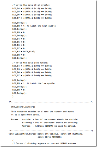
Note that in these examples – as in the RS-232 library – we have implemented the library as a MUL TI ST AGE T ASK : each character is written to a buffer and updates of the LCD display itself are carried out with a scheduled ‘update’ function.

Note also that these examples illustrate the use of user-defined characters.

Hardware resource implications

Uses a number of port pins, plus one timer.

Reliability and safety issues

LCD displays are reliable and have a long life.

Portability

This pattern can be applied to any microcontroller family.

Overall strengths and weaknesses

LCDs provide the basis of a professional and flexible user interface.

The panels are not cheap.

Even a ‘4-bit’ interface requires six pins.

Related patterns and alternative solutions

● See MX LED DISPLA Y [page 450]

● See PC LINK ( RS -232) [page 362]


Multiplexed LED displays:Hardware resource implications

Hardware resource implications

All the examples here require the use of a scheduler. The main resource implication is that, to update (say) four digits, you need a scheduler with a tick interval of around 5 ms. This is not usually a limiting factor. Overall, the LED update code will consume only around 1% of the CPU time in a typical application, since – although frequent – it is a simple and fast operation.

The memory requirements are minimal.

A substantial number of port pins are required.

Reliability and safety implications

LEDs are not visible in bright light and, as such, must be used with care if they are displaying safety-related information.

For multiplexed displays, you must ensure that the application (or scheduler) cannot become locked: if it does, the display will very quickly be destroyed by high current values. Thus, if a poorly designed task blocks the scheduler, even for a few seconds, and delays a display update (usually scheduled around 20 to 50 Hz), you will probably destroy the display. Whatever happens, you need to ensure that such an event will not impact on the general operation of the microcontroller and, therefore, completely destroy the application.

Portability

These techniques are easily ported across members of the 8051 family and to any other processor family. No features unique to the 8051 are employed.

Overall strengths and weaknesses

Multi-segment LED displays are reliable and cheap.

The techniques discussed in this pattern are easy to apply and highly portable.

A typical interface requires a substantial number of port pins: up to 12 pins for a multiplexed 4-digit display.

Displays are not visible in bright sunlight. Provide an additional audible warning if necessary.

Multiplexed displays can suffer from reliability problems if the scheduling is not handled correctly.

Related patterns and alternative solutions

There are numerous ‘intelligent’ LED drivers, such as the Maxim 7219, that can deal with the task of driving and multiplexing LED displays for you. These usually have a serial interface and, as a result, require few port pins. This can be a useful solution if port availability is limited.

Another way of reducing port requirements is to use a version of the 74×247, BCD- to-7-segment decoder IC as an interface to your displays, as illustrated in Figure 21.7. The main problem with this approach is that the 74×247 is no longer widely avail- able. If you can find a good supply and are assured of future supplies, this device is easy to use: consult the data sheet for details.

Another alternative, if lack of ports is a problem, is to use an additional Small 8051 in your design. This chip will then be responsible for the display multiplexing and updates: data can be easily transferred to such a device using a serial interface and a shared-clock scheduler (Figure 21.8). Shared-clock schedulers are discussed in Part F.

image


Controlling LCD panels

Introduction

We considered the creation of LED-based user interfaces in Chapter 21. Here we are concerned with the use of liquid crystal displays (LCDs) in such interfaces.

Unlike LEDs, LCDs are based on passive display technology: this means that LCDs control the passage of light rather than emitting light. This fact directly contributes to the low power consumption of these devices: large (5V) panels require up to 5 mA: a total power consumption of up to 25 mW, excluding any backlight. Small panels con- sume around half this power. Since a single LED has a very similar power consumption, use of LCD displays in battery-powered embedded systems is particularly popular.

While various types of LCD display are available, they can be divided into two basic groups: graphics displays and text displays. Notebook (and increasingly desktop) PCs use sophisticated graphics displays, made up of many thousands of individual ‘picture elements’ (pixels). Such displays are expensive in their own right and generally require large amounts of memory (typically several megabytes) and powerful processors for efficient operation. As we have seen, the type of embedded devices we are concerned with in this book do not usually justify this level of expense. Instead, we will be concerned here with small displays intended primarily to display text.

Various types of LCD-based character displays are available. These are typically arranged as one, two or four lines of between 16 and 40 characters. Inevitably, the larger displays are more expensive and consume more power. Each LCD character is usually a 5×8 matrix of dots: less commonly, a 5×11 matrix is also used: note that, in each case, the characters themselves are 5×7 and 5×10 pixels in size, with the bottom line being reserved for the cursor. To generate characters on such displays would tend to consume a large percentage of the available CPU time (and most of the ports or address space) on most embedded processors. As a result, most LCD panels include an on-board controller to deal with this: this is generally a variant on the Hitachi HD44780. Displays based on this popular controller all have very similar hardware interfaces and will display the same mixture of English (or Japanese) characters.

We focus on LCD panels based on this ‘standard’ controller in the pattern LCD CHARACTER P ANEL presented in this chapter.

Please note that much of the background material presented here is adapted from the Hitachi HD44780 data sheet.


Keypad interfaces:Hardware resource implications

Hardware resource implications

While it does not require on-chip facilities (such as timers etc.), the keypad scanning process imposes both a CPU and memory load.

Reliability and safety issues

Keypad scanning is a software-based technique, closely related to SWITCH INTERF ACE ( SOFTW ARE ) [page 399]. In a hostile environment, use of a keypad may provide a less reliable solution than use of a number of individual switches with a hardware inter- face (see SWITCH INTERF ACE ( HARDW ARE ) [page 410]).

However, particularly where a large keypad – such as a QWERTY keypad with around 30 keys – is required, use of separate switches may be impractical. The safest thing to do in such circumstances may be to use a shared-clock scheduler (see Part F), and have a second microcontroller link to the keypad. This ‘keypad microcontroller’ should then have a separate power supply, and should be opto-isolated from the main system board.

Portability

This code is highly portable and this approach to keypad scanning is very widely used.

Overall strengths and weaknesses

Multiplexed keypads are easy to use and inexpensive.

Because the pattern is software based, minimal protection against ESD and malicious damage (for example) is provided: use of a separate, isolated, keypad processor may be necessary if the reliability of the main processor is essential.

In harsh environments, it may be safer to avoid multiplexed keypads and use individual switches.

Related patterns and alternative solutions

See SWITCH INTERF ACE ( SOFTW ARE ) [page 399] and SWITCH INTERF ACE ( HARDW ARE ) [page 410].


Example: Using a dedicated baud rate generator

Example: Using a dedicated baud rate generator

As we noted in ‘Solution’, some 8051 microcontrollers have a timer dedicated to baud rate generation. This can be a useful facility, since it leaves us (usually) with three free timers for use in the scheduler, creation of delays and so on.

In this example, we present an ‘output only’ library for the Infineon C515c (list- ings 18.6 to 18.11). This uses the C515C baud rate generator. In the example, we display elapsed time on the screen of a PC or similar terminal.

There are two main points to note in this example:

● The library is considerably smaller and simpler than the ‘duplex’ library presented earlier.

● The microcontroller is running at 10 MHz; despite this, the internal baud rate gen- erator allows us to create a very accurate baud rate for the serial link. This is a very useful feature.

image

image

image

image

image

image

image

image

image

image